

During repairs or alterations, you have to constantly change the probes of the multimeter to measure a particular voltage. It also helps to measure the resistance between the output voltages of the power supply. After sitting and thinking, I decided to assemble a module for quickly switching between voltages. A certain number of non-working computer power supplies were overloaded. I decided to repair them.
For homemade we will need:
- plastic sheet;
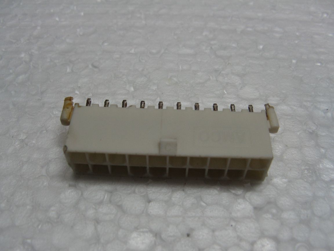
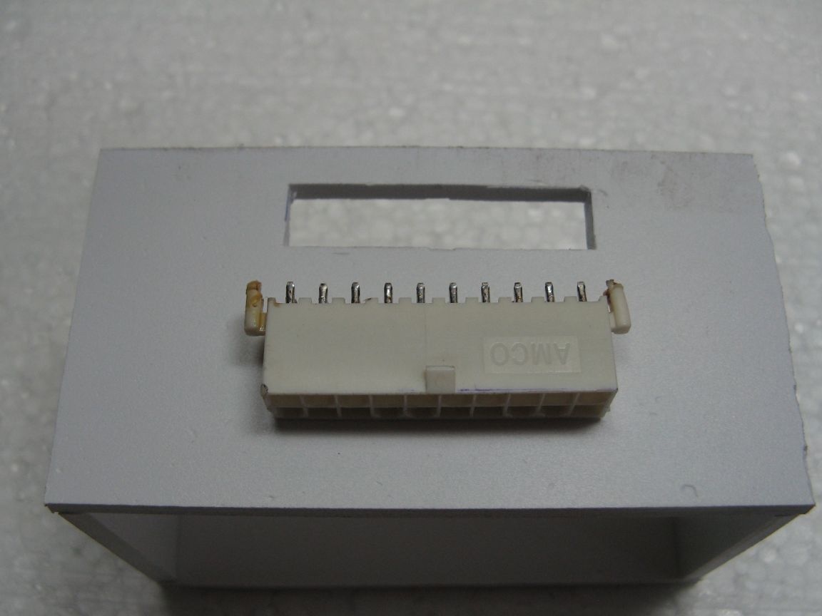
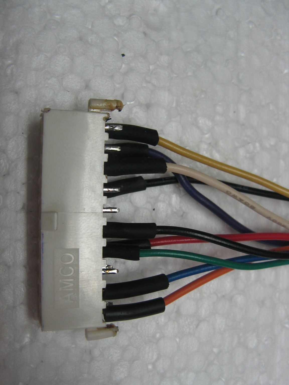
- power connector motherboard;
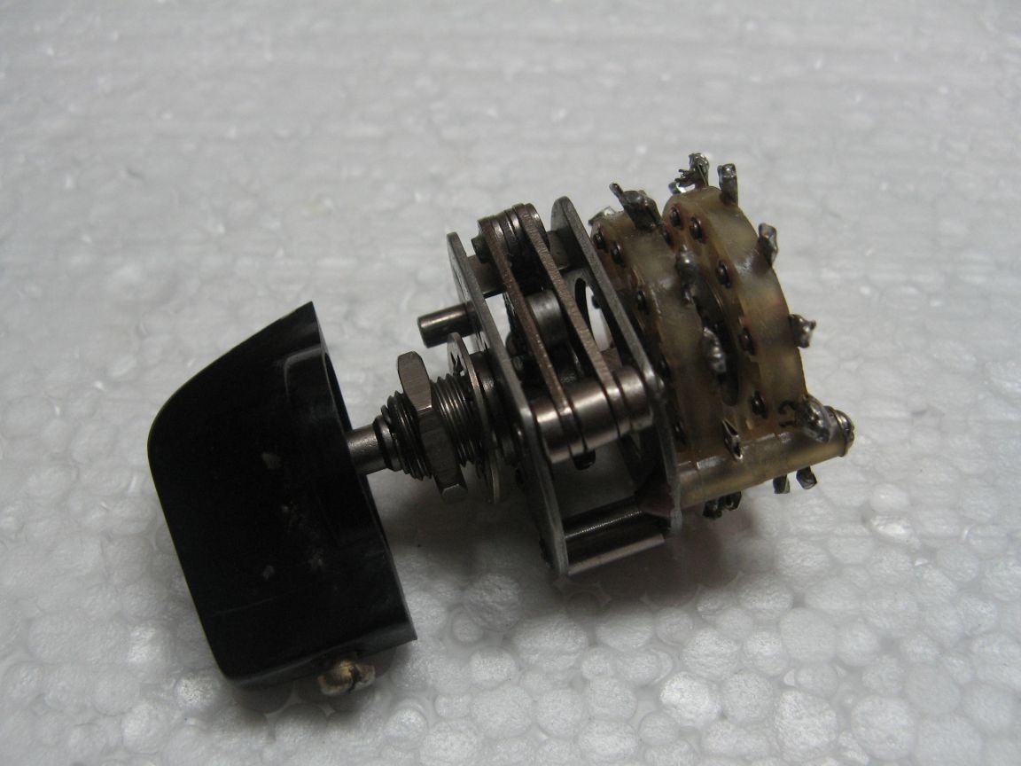
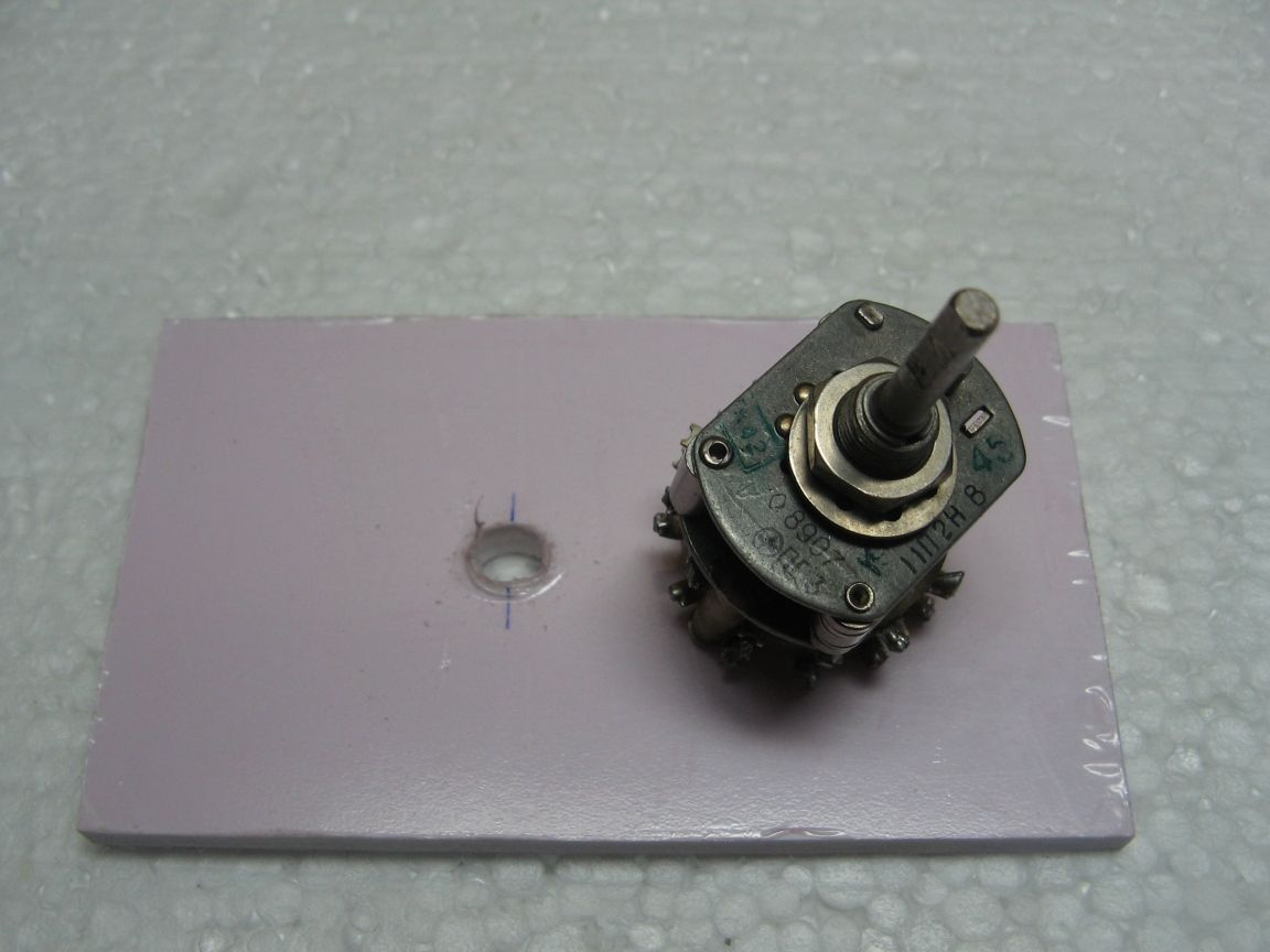
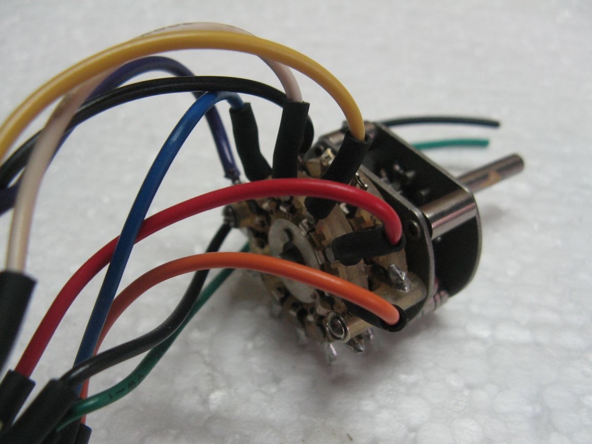
- PG3 biscuit switch;
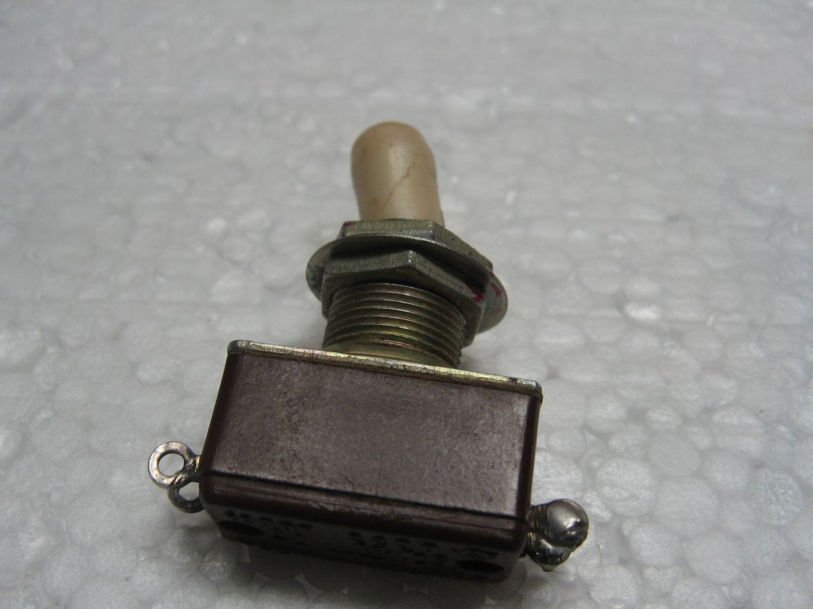
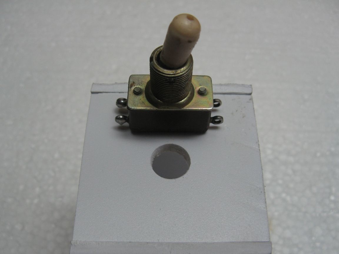
- switch;
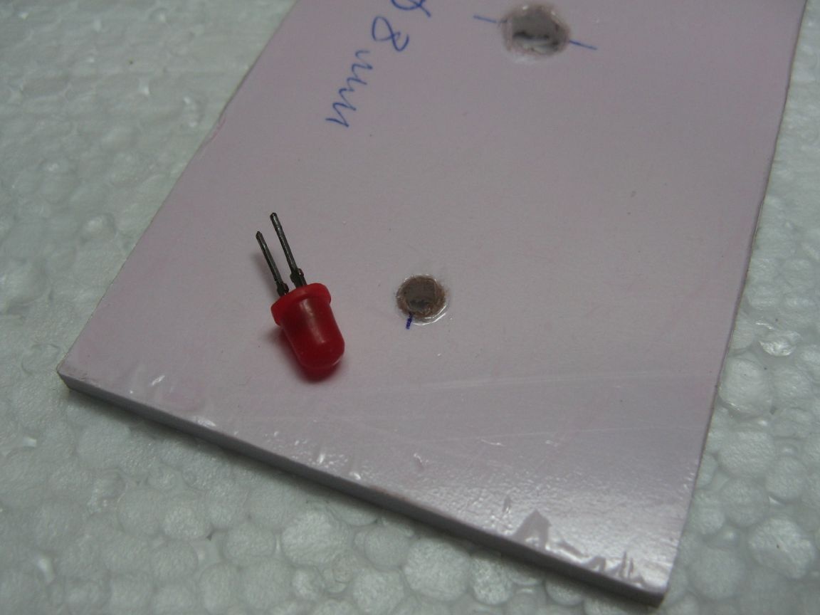
- Light-emitting diode;
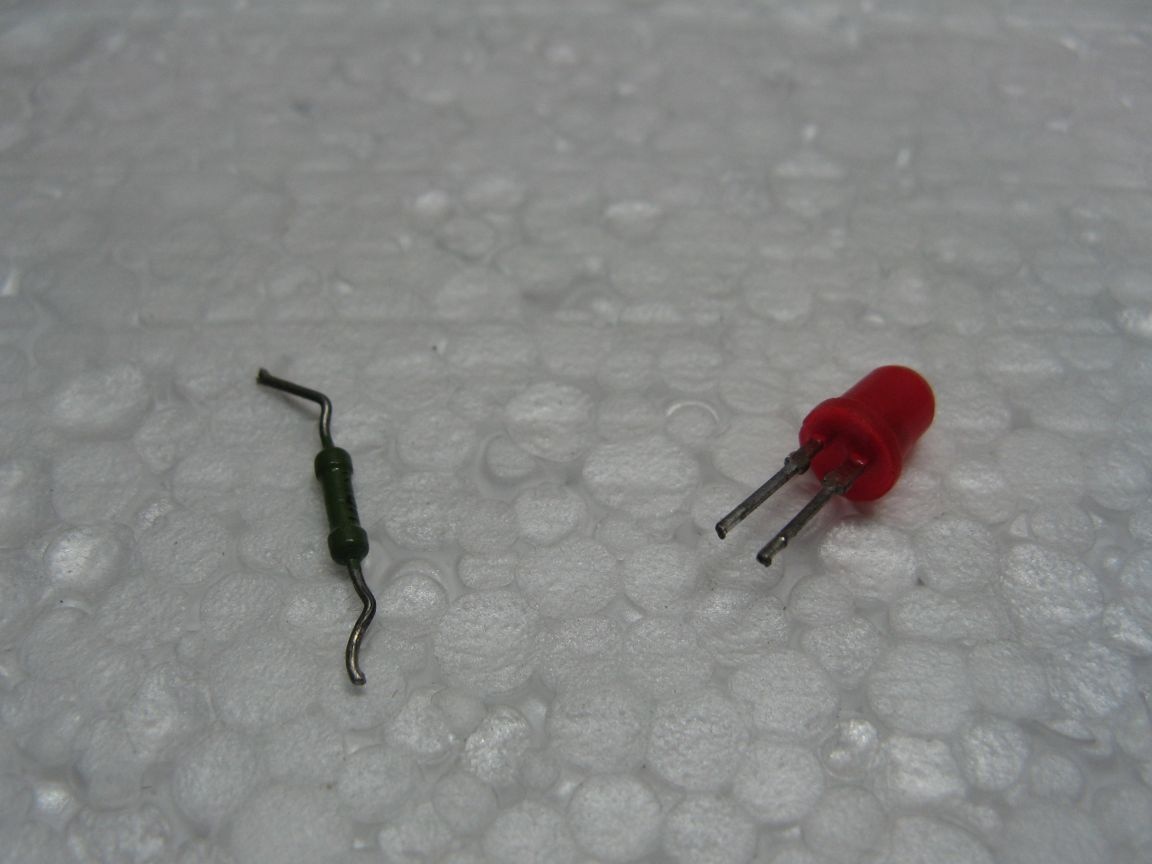
- resistor;
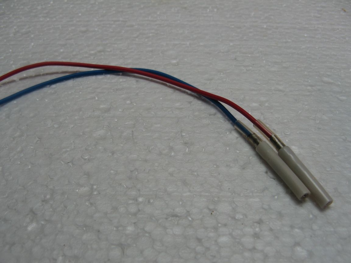
- terminals;
- soldering iron, tools.
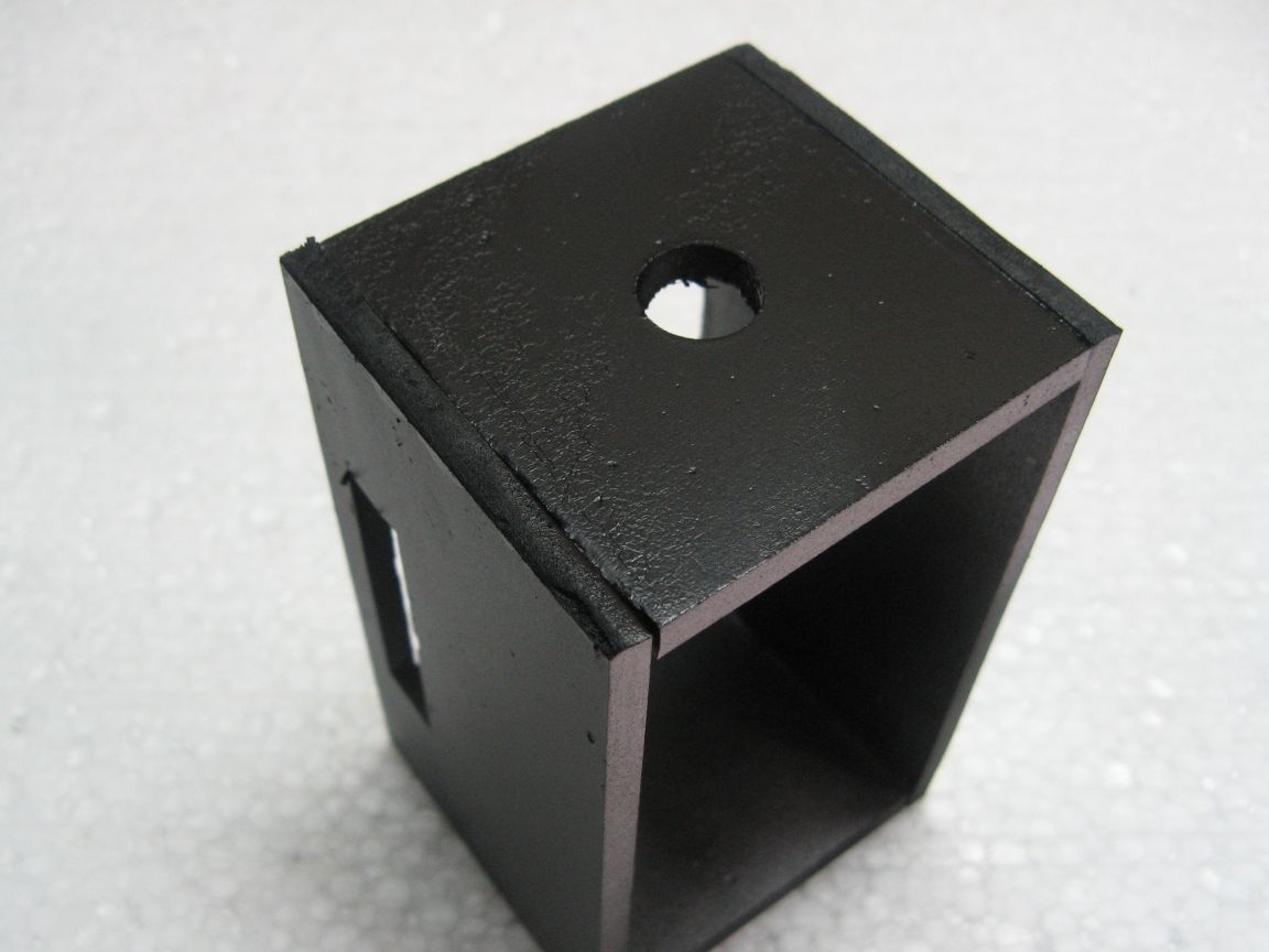
The body of the device will be made of PVC sheet plastic. Plastic can be applied differently. I got mine from the advertisers, they throw the trimmings out. The housing can be applied any suitable. A junction box is very good.

I dropped the power supply connector from the old motherboard. You can apply to 24 contacts, I applied to 20.
I had a wrench switch. It was soon removed from the old equipment. Need for 6 positions, but I have 11. I will apply what is. The beak was also picked up, more precisely the handle for the switch.
Any switch can be used. Be it with two normally open contact groups. Or with one group. I took the toggle switch from the old TV.
The indicator of the module and power supply will be an LED. It is connected through a current limiting resistor of 150 Ohms.
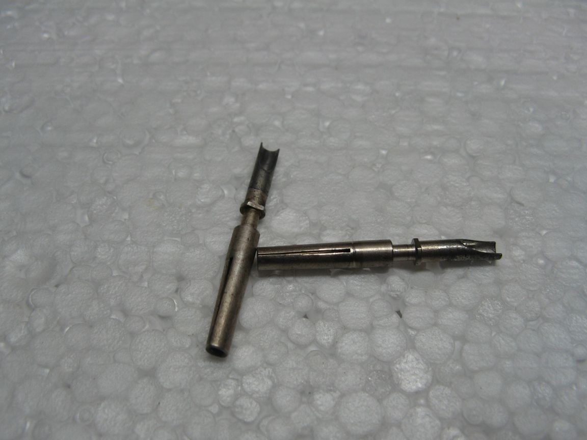
Long thought about how to connect a multimeter to the module, or rather its probes. I did not find anything suitable, except for the contacts of the military connector of the SR.
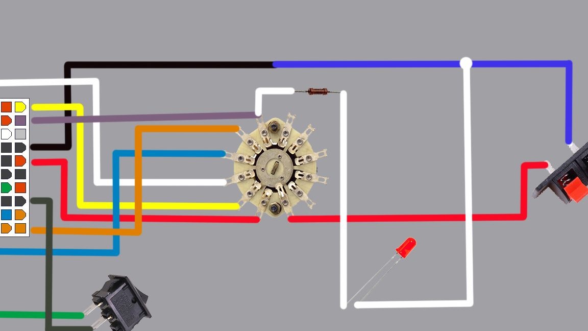
Scheme.
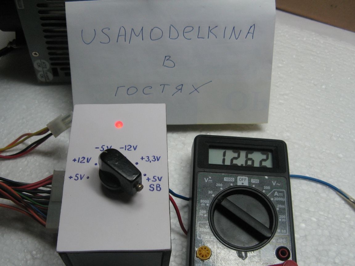
According to the scheme, the module is very simple. The tested power supply is connected to the connector. To the output terminals of the multimeter. Immediately the LED lights up, indicating the presence of a 5 Volt duty room. The block does not start. Press the switch and the unit should start. The multimeter shows the output voltage set by the switch of a switch. Changing the position of the biscuit, we change the voltage at the terminals.They should be normal. Voltages are indicated on the case of the tested power supply. In this way, the resistance of the output voltages is checked. If the voltage is normal, then it makes no sense to check the resistance.
Also, any device can be connected to this module. If, for example, we need to supply something from 3.3 V. We set the desired voltage with the handler. The main thing is not to exceed the current that the contacts of the dial switch can pass.
Assembly process.
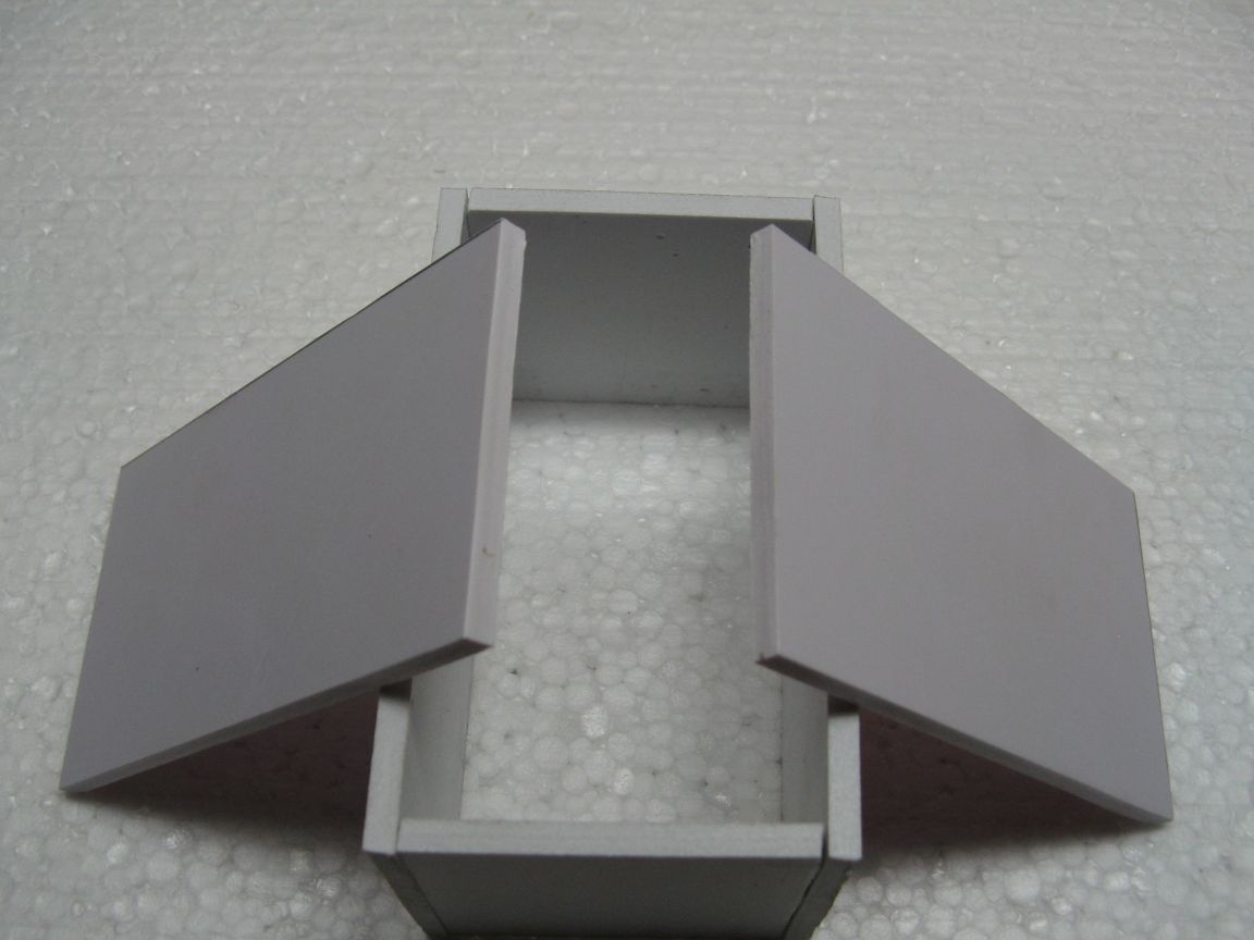
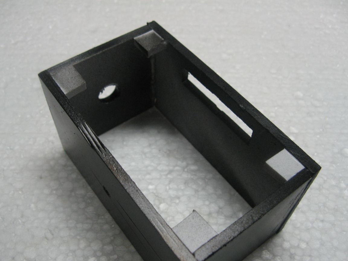
From plastic, we cut out the blanks of the workpiece of the size we need. Glue in the form of the letter "O". Everything sticks to super glue. We also cut out two plates, the size for closing the case. Plates are needed for the back and front panels.
We cut out the window under our connector. I have it on the right. Location is not important.
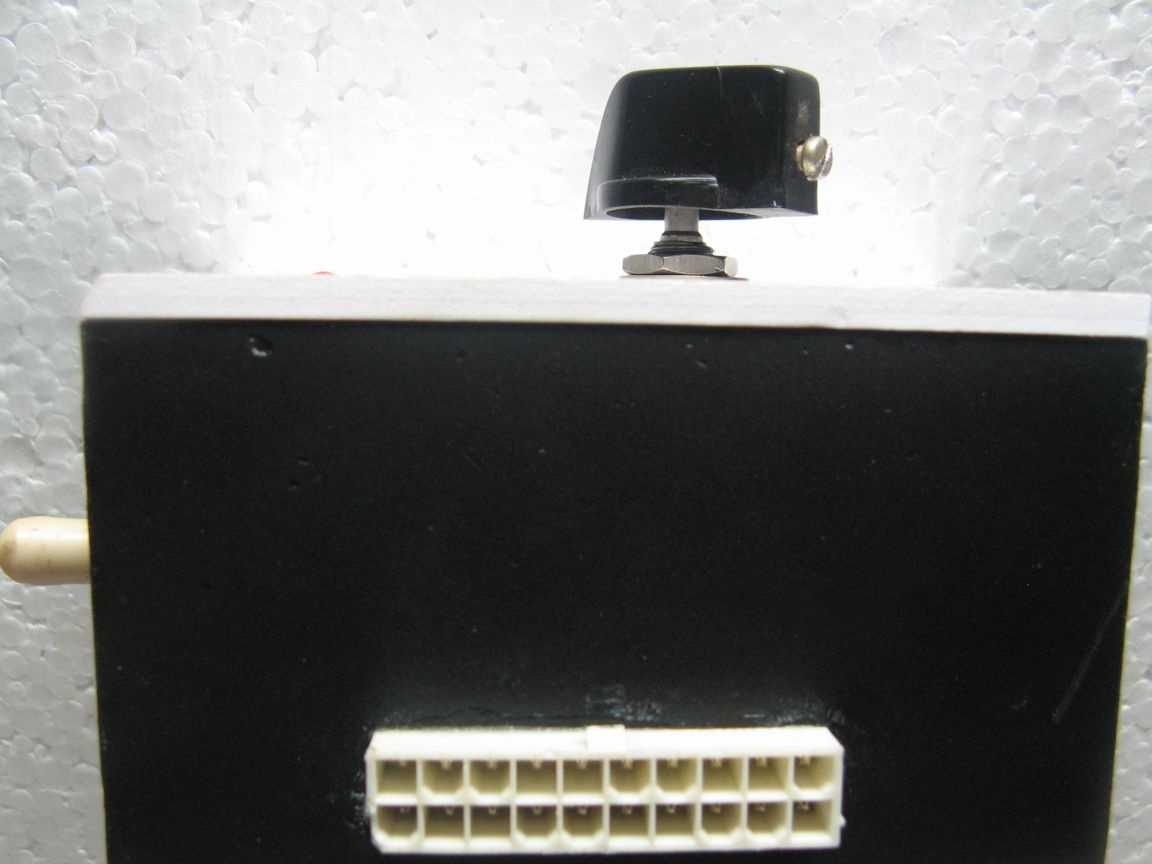
In the upper part of the housing, we drill a hole for the switch.
In the blank for the front panel, I drill a hole for the wrench switch. It also has a key for installation. I will drill a hole under it. It will be seen later.
I also drill a hole for the LED. I have it at 5mm, I drilled a hole of a smaller diameter. So the LED is held tight.
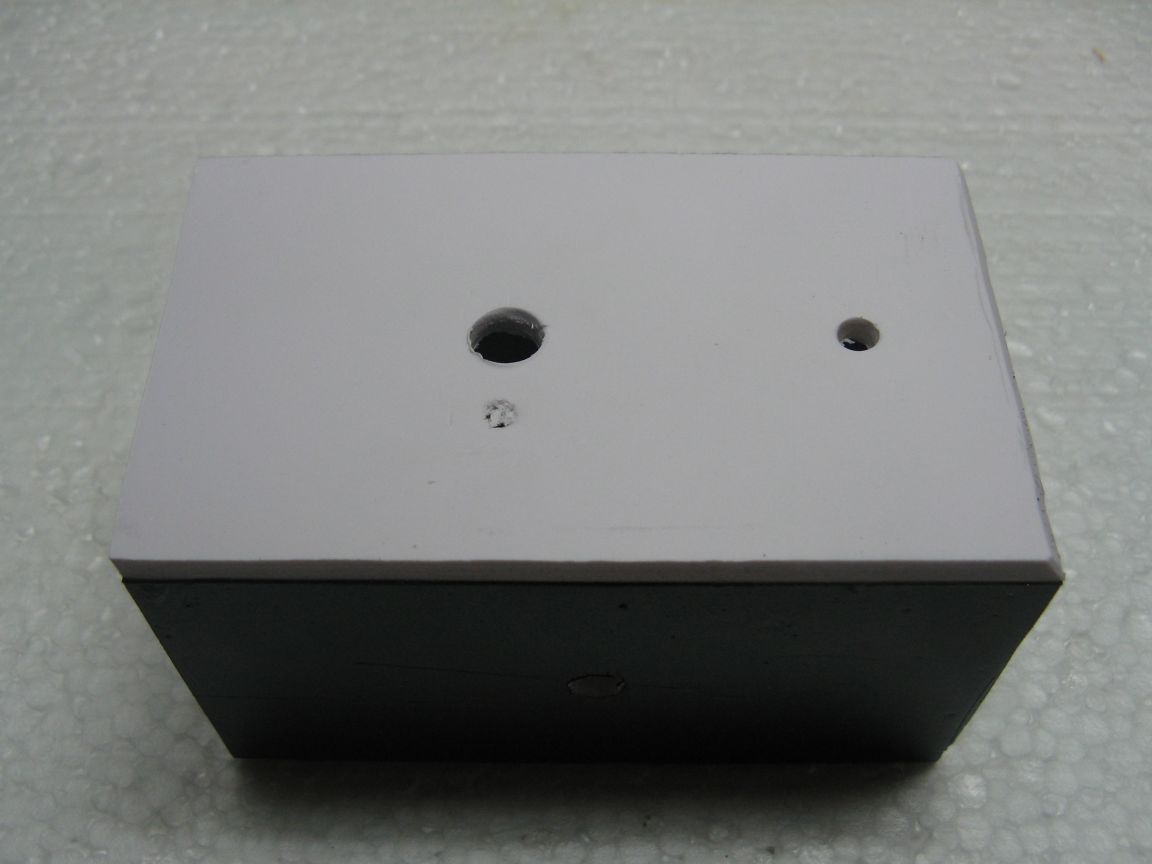
The main body decided to paint from a spray can. I paint the case in black.
While the base of the casing dries, proceed to the wiring of the circuit. Solder the wires to the connector according to the colors of the power supply. It is convenient to solder by docking both connectors. We need: +5, +12, -5, -12, +3.3 and on-duty 5 V. We also solder the wires to green and black, they will go to the start switch.
We unsolder the biscuit switch according to the scheme.
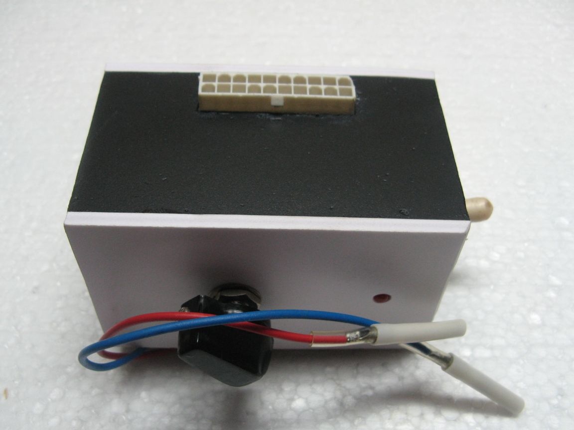
We solder the terminals to the output wires and isolate them. I made them of different lengths to exclude a short circuit.
The front panel will be glued to super glue, and the back to small screws. For the rear panel, you need places in which the screws will be screwed. Glued a piece of plastic in the corners. It turned out something like "nuts."
I glued the front panel. You can see in the photo a turnkey hole for the switch of a switch.
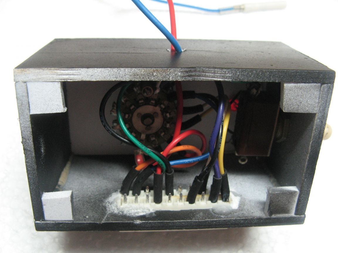
Next, I fix the dial switch. I set the switch. I also solder an LED with a resistor to the wires of the standby voltage. I deduce output wires.
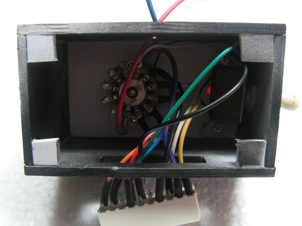
I will fasten the connector for connecting the tested power supply to super glue with soda or salt. It is possible for hot-melt adhesive, but I had it at that moment over.
I fasten the back panel to the screws and the module is ready.
When assembling, I changed the position of the wires on the wrench switch. Found it so more convenient. We connect the tested unit to our module. By switching the position of the biscuit, we control the output voltage or resistance.
Video on the assembly of this module: