» Topics » DIY ideas »Driver for led lamp 10w version 2 with ballast and protection

Driver for led lamp 10w version 2 with ballast and protection

He said once, then I can say two! I could not calm down, and continued my search for a good and easy to repeat driver circuit for a 10-watt lamp. And found! How much good can be found in the archives of Radio magazine. He came up with a scheme, A. KARPACHEV, from Zheleznogorsk, Kursk Region which he published in a rather recent issue of this year’s magazine, Radio 6, 2018, in an article; "High-voltage mains power supply with quenching capacitor and protection." For which many thanks to him!

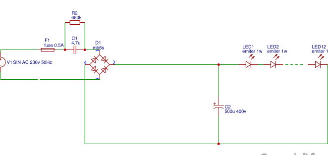
Let's start with the analysis of the classical circuit with a ballast capacitor. The ballast capacitor C1, being a current source, having received voltage from the fuse F1 and the limiting resistor R1, which is designed to protect the ballast from the inrush current when it is switched on for the first time, limits the current, and the direct current source rectified by the diode bridge D1 is directed to the led1-led12 LED circuit. The advantages of this scheme are simplicity, accessibility of parts, not afraid of KZ at the output. But there are significant drawbacks: 1. The presence of pulsations of 100 Hz at the output of the filtering capacitor, which, however, can be removed by increasing the capacity of the filtering capacitor C2 to 500 μf, since after the diode bridge the voltage amplitude reaches up to 310 volts, then the filtering capacitor must withstand this voltage, select it plus some margin, away from sin, let it be 400 volts, and now imagine what its dimensions will be.

The following two points of the disadvantages of this scheme follow from this.

2. Dimensions of the filtering capacitor.
3. The high cost of a filtering capacitor with such parameters.
And usually hams compromise, either put a filter capacitor with a lower capacity, but at a high voltage, or given the fact that when connected
ice of the chain there is a voltage drop equal to the sum of the voltages of all ice elements which is subtracted from the input voltage in front of the ice chain, this voltage plus some margin and the voltage of the filtering capacitor C2 is selected.
Which seems to save the situation but is a bad and even dangerous decision, since when one of the LEDs is burned, a chain of series-connected LEDs is disconnected from the source, and as a result, the voltage on the filtering capacitor rises sharply to a value of 310 volts, and since the electrolytic the capacitor becomes the load itself, begins to boil and can fail, causing an emergency with bad consequences. The above is the fourth drawback and all of the above crosses out the simplicity and cheapness of the scheme ... But thanks to A. KARPACHEV, from Zheleznogorsk, Kursk region. he figured out how to get around this, and created a circuit that protects the filtering capacitor from overvoltage, and the protection works when the ballast capacitor is burned and shorted, and the circuit allows you to apply lower voltage to the LED circuit, and as a result choose a smaller capacitor , which will reduce the dimensions of the device itself and also choose a large filter capacitor C2

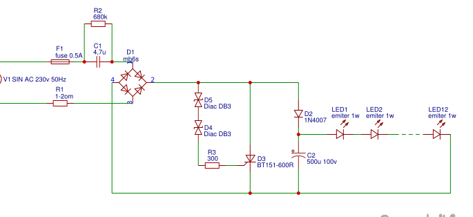
The essence of the circuit is that the mains voltage passing through the limiting resistor R1 and the fuse F1 gets to the Ballast capacitor C1, is limited by current, then rectified by the diode bridge D1, then it goes to the diode D2 through which the capacitor C2, in turn, is charged, at the same time the moment when the voltage at the input of the dynistors D4-D5 increases to the breakdown voltage of the dynistors, the thyristor will open briefly and short-circuit the diode D2 and capacitor C2, due to which the capacitor will begin to discharge while s are closed to the breakdown voltage, in fact we get a kind of stabilization and protection of the filter capacitor overvoltage if, for any reason disappear load, that is, one of the LEDs will burn, or burn the ballast capacitor. Referring to the description of the DB3 parameters, its breakdown voltage is 28-32 volts, in a 10-watt led lamp I used a chain of 12 1-watt LEDs, then the voltage of 32 volts is clearly not enough for me, and therefore I put two dinistors in series, raising the breakdown voltage to 61 volts. Since I bought LEDs from China, I decided not to overload them, and I swung the LEDs to 0.7-0.8 watts, choosing a ballast capacitor capacity of 4.3-4.7 microfarads. The capacity of the ballast capacitor can be calculated as follows, we multiply the capacity of the ballast by 0.051 ml and accordingly we obtain the output current (in general, we need to multiply by 0.065, but these 0.051 ml were empirically determined, to see 0.014 ml takes on the protective circuit from the diac and thyristor, but we do not greedy, let them eat), the LEDs are good, they shine brightly, that is, they give out their declared 100 lumens. The vd2 diode protects the dynistor input from a voltage surge when the thyristor is closed, while locking securely.

According to the author’s recommendation, the limiting resistor R1 needs to be placed in an insulating tube made of fiberglass, choose a Ballast capacitor K73-17 at 630 volts, I used Chinese Cbb 3.3 microfarads at 630 volts +1 microfarads at 630 volts, it turns out cheaper, the thyristor must withstand no less 10 amperes and also a voltage of at least 300 volts, so I chose bt151 r600, even the bt139 triac can come up, which of course is wasteful, but I didn’t have a thyristor and I used a triac, in this inclusion it is also suitable. That's all, thank you for your attention and successful finds and assemblies. Thanks again to the author of this scheme, and in general I strongly recommend that you read his article, he has described everything more meticulous and competent, my modest goal is to popularize his scheme, which I really liked ...
Question \ topic is automatically published in the social. site network - stay tuned for answers there:

Suitable for topic

Related topics

Add a comment

    • smilesmilesxaxaokdontknowyahoonea
      bossscratchfoolyesyes-yesaggressivesecret
      sorrydancedance2dance3pardonhelpdrinks
      stopfriendsgoodgoodgoodwhistleswoontongue
      smokeclappingcraydeclarederisivedon-t_mentiondownload
      heatirefullaugh1mdameetingmoskingnegative
      not_ipopcornpunishreadscarescaressearch
      tauntthank_youthisto_clueumnikacuteagree
      badbeeeblack_eyeblum3blushboastboredom
      censoredpleasantrysecret2threatenvictoryyusun_bespectacled
      shokrespektlolprevedwelcomekrutoyya_za
      ya_dobryihelperne_huliganne_othodifludbanclose
32 commentary
Guest Vladimir
There was more discussion of email. a network rather than a circuit. I wonder if it’s possible to get power for a 12 V DC device. current approx. 40 mA based on this circuit?
Author
Ivan Pokhmeliyev, my apologies for the tone, I really liked the scheme, and therefore I invest emotionally ...
Quote: Totiks
This stuffing-dispute about the voltage can be seen due to the voltage of the filtering capacitor, but pay attention to the dynistor-thyristor circuit,
You will be surprised, but there are no questions to the main content of your article, everything is clear.
from your comments it is advisable to choose a thyristor for a voltage of 600 volts, and for those who are completely paranoid put a capacitor at 400 volts
The conclusion is wrong, there was not a word about such a proposal.
There was a clarification of your own words
after the diode bridge, the voltage amplitude reaches up to 310 volts,
, no more. )))
Author
Oh and flooded that, oh well, live communication is good, this stuffing dispute about the voltage is seen due to the voltage of the filtering capacitor, but pay attention to the thyristor-thyristor circuit, it will not allow the voltage to rise above the breakdown voltage of the dinistor, it’s advisable to choose from your comments a thyristor for a voltage of 600 volts, and for those who are completely paranoid to put a capacitor at 400 volts :), and hide the driver itself in the pantry ... I imitated different types of accidents, LED burning does not affect the driver and output capacitors, well, maybe all at once, becoming a conductor, in this case the input ballast resistor will fly out, after it the fuse will fly out, I short-circuit the ballast itself, again the protection works, but in this case the LED line comes out, or rather the weakest one of the LEDs, in general the driver is more safer than previous with capacitor divider.
The same circuit can be used as a power supply, but swinging above 0.4-0.5 Amperes is not advisable, as part of the current it takes on the protection circuit.
How many such kotorie, as you understand, are not connected to the common network, rather very few, in the grandmother’s village there is a mini HES, but it works in the common network.

Recently I was at our waste recycling plant ... There is also such an incident - their power plant (which works with "waste gases", supplies current to the general network ... (At the same time, of course, for "cheap"). And the plant powered by tariffs for production !!! And no one allows them to take part of their own free energy for the needs of the plant !!!!
In the 90s, they made wiring for a computer class at school. There only copper wiring is allowed.

And where is another being put ??? Now everywhere on sockets - VVG 3x2.5, for lighting - 3x1.5 ... AVVG is still for some reason sold (apparently, repairing old wiring), but nowhere is it put "cleanly".
Telecommunications operators (mobile, landline, Internet) can use these lines

Who will let them go there? Draconian conditions are imposed on the use of OHL poles for power optics! And Khatul Madan is right, a lot of information on aluminum cannot be conveyed. And on the rail on the rail information is really transmitted. In the Soviet army, signalmen were taught to use rails as wires, so the rails are not "ground."
pogranec
On the rails? This is even more interesting, the rails are the same land, and there are no filters there, it turns out that when I transmit information through the earth at some (passing through it) frequency, can they receive it in America?
I am writing only what I know and saw. Apparently there are some difficulties if they prefer to pull optical fiber over existing supports.
Khatul Madan
"-in view of the stupidity of customers"))
Communication within the network of one transformer substation, it is visible substation coils act as a filter. Here Korolev writes that on high-voltage lines it is possible to continue to receive a signal ("via OHL - 35 kV was received in the neighboring region!"). Telecommunications operators (mobile, landline, Internet) can use these lines, then they don’t need to lay extra wires (telephone) or poke base stations everywhere, or even broadcast radio, broadcast television, right?
New Standard,
About 15 years ago there were Chinese intercoms using the network as a communication line. I put them on a recreation center for communication between clients and the administrator (later they removed it due to the stupidity of customers). I don’t remember the distance and the connection itself within the network of one TP, and it seems like in one phase. Naturally, there was no technical description, much less a scheme. The connection was simplex, pressed the button, say, listen to the rest of the time.
New Standard,
You can create one intercom or even the Internet via 220 V networks

You understood correctly, it’s not only possible, but it’s also applied, I had a case when, with a faulty connection filter, my communication channel over the OHL - 35 kV was received in the neighboring region!
In our city there was a provider who distributed the Internet in apartment buildings via an electric network. The signals are transmitted to the train in the cab of the electric locomotive on rails.
Korolev
You can create one intercom or even the Internet over 220 V networks for a distance
(I wonder what?) if no one controls))
"can not be transmitted over the network 220 to high-frequency signals?" Until now, in a lot of power systems, overhead lines transmit telemechanics, telephony, etc. via HF, mainly up to 980 kHz. With poor filtration, it can leak to the consumer. There are also systems for transmitting digital streams (Internet) over a home electrical network.
Ivan_Pokhmelev
How many such kotorie, as you understand, are not connected to the common network, rather very few, in the grandmother’s village there is a mini HES, but it works in the common network. Some put solar panels up to 30 kW on the farm and they try to connect to the network in order to "mow cabbage" on a "green tariff". A quarry in the village, when the engines were turned on there, the lights went out a bit, right now there is almost no, but aligarchs work, damn it, sometimes they rock the rock all night. For the sake of interest, I checked with a frequency meter that sometimes drops below 49 Hz, though for a short time up to 5 s. I also often noticed strong interference and interference going through the network, then someone is turning on something powerful (CB, HF band is not possible to listen to) interference must also have its own allowed rate on the network, for example, it is impossible to transmit 220 V over the network high frequency signals?
Yes, I was sure of the standard, I did not know that such crap would be legalized.
Quote: New Standard
In villages and at frequencies less than 49 Hz it is allowed,
This is only possible if your own DES is worth it. Somewhere in small, very remote settlements, this happens. Do you have many such villages in Ukraine?
Quote: Khatul Madan
though I haven’t met more than 245,
This does not mean that there can be no more. Moreover, it is impossible to draw conclusions in special cases. So what you want, you don’t want, but we must take into account that the appearance of 253 V.
When I installed the UZM-51M, I first set a maximum of 240 V - after some time the protection worked, switched to 245, a few months passed - it worked again. Now it has been 250 for a long time, there were no more trips.
Quote: Pronin
I do not see the layer of work.
Replacement of transformers on TP. Somewhere you can switch the taps, somewhere already and at the limit it works. These are tens of thousands of transformers. They must be produced, then replaced with old transformers, tested and adjusted at the installation site. Each stage costs a lot of money.And the equipment connected to the network? The standards apply not only to the household network, but also to industrial enterprises, that is, everything must be agreed with these consumers.
I am too lazy to look for data on the norms of voltage in the network, I’ll say that in a city there are more stringent norms than in a village. In villages and at a frequency of less than 49 Hz it is allowed, and beyond 198-250, too, but who checks it especially for the weekend, it is only for a piece of paper, in serious enterprises where expensive equipment is installed there are always stabilizers, or their own generation. When increasing from 220 V to 230 V, the bulbs of course hosh not hosh will have to be changed, they burn, for more expensive ones))
It seems that “at the request of the workers” they found a simple solution, it’s easier to switch the ansaf on the existing transformer and add up to 200 V for someone else than to install another transformer. And do not care about those who live near the TP with a voltage of 250 in the outlet, answer, put the stabilizer. Faced with one and the other, though I haven’t met more than 245, and considered it a special case. Some complain that the bulbs quickly burn out (both energy-saving and LED ones), while others refuse to turn on household appliances (<190 V).
Entot looked new GOST 29322-2014. Really laid the type of value of the nominal voltage - 230V.
But, this is the voltage at the input (per object). And there are tapers and a new one - "Used voltage". This is that in the outlet! And it can differ by -3% (only minus) (Dimon's bulbs) and -5% (to sockets). It is clear that the wiring from Alumen (with a drop, for example) and the currents of consumers increased - iron 2 kW, kettle 2 kW, pressure cooker and microwave 1,5 kW and so on.
Measured in the outlet ~ 229v. At night above and with incl. light bulb D, it sometimes burns out.
... but this is a huge layer of work with gigantic financial costs,

I do not see the layer of work. Prohibit incandescent bulbs on more expensive Ketai? and TP pointers - this is a layer ?? derisive
In the 90s, they made wiring for a computer class at school. There only copper wiring is allowed.
Even if there is 400 in the network (which happens in villages, after a hurricane) and something burns out in you, I wonder how you will prove that it is through high voltage, but yes, invite an expert, and in terms of use, "consumer obligations "- it is written that the consumer himself is responsible for protecting his devices from overvoltage, oddly enough, so the electrolyte must not be put on 400 but on all 800 in, just in case, but the fuse is really very important there, why doesn’t it react to high voltage, only current))
GOST 29322-2014 Standard voltages. Table A.1. Highest supply voltage 253 V.
As I wrote above, 230 * 1.1 = 253.
PUE is a valid, but extremely inertial document. And it is right. Many chapters did not pass state registration. Some chapters of the sixth edition have not yet been reprinted, in particular, the most important chapter 7.3. The transition to 0.23 / 0.4 was laid down in GOST 29322-92, but this is a huge layer of work with enormous financial costs, so there are still 220 V in places (and, in fact, lower).
Yesterday I measured the house at the outlet - approximately 238-239 V.
In the rules for the installation of electrical installations (PUE-7), the value 220 continues to appear, but in fact, the voltage in the network is almost always higher than this value and reaches 230-240 V, varying from 190 to 250 V.
Wikipedia Although 220 + 10 / -5% is indicated in the contracts, I always calculated on the basis of 240 V.
Quote: Khatul Madan
Do we have 250 V in our network?
I have to explain.
The mains voltage is 230 V. We multiply by the root of 2, we get the amplitude. Multiply by 1.1 (tolerance plus). Subtract 1.5 V (drop on two diodes). We get 356 V.
Do we have 250 V in our network?
It is this voltage that can reach 356 V. Count at your leisure.
Author
310 volts means the voltage rectified and filtered by the output capacitor.
after the diode bridge, the voltage amplitude reaches up to 310 volts,
I don’t know how in Ukraine, but in Russia it can actually reach 356 V when the network is working within acceptable limits, but when one of the LEDs breaks.
Author
After publishing the circuit, on the recommendation of the author in his article, to more accurately control the amplitude of the output voltage, I tried to put a zener diode instead of a VD5 dynistor at a lower voltage, I put a zener diode at 12 volts, in total with a threshold of a dynistor of 28-32 volts I got 42 -44 volts, which further improved the operating mode of the LEDs, the heating of the LEDs decreased, which should positively affect their service life.

We advise you to read:

Hand it for the smartphone ...