
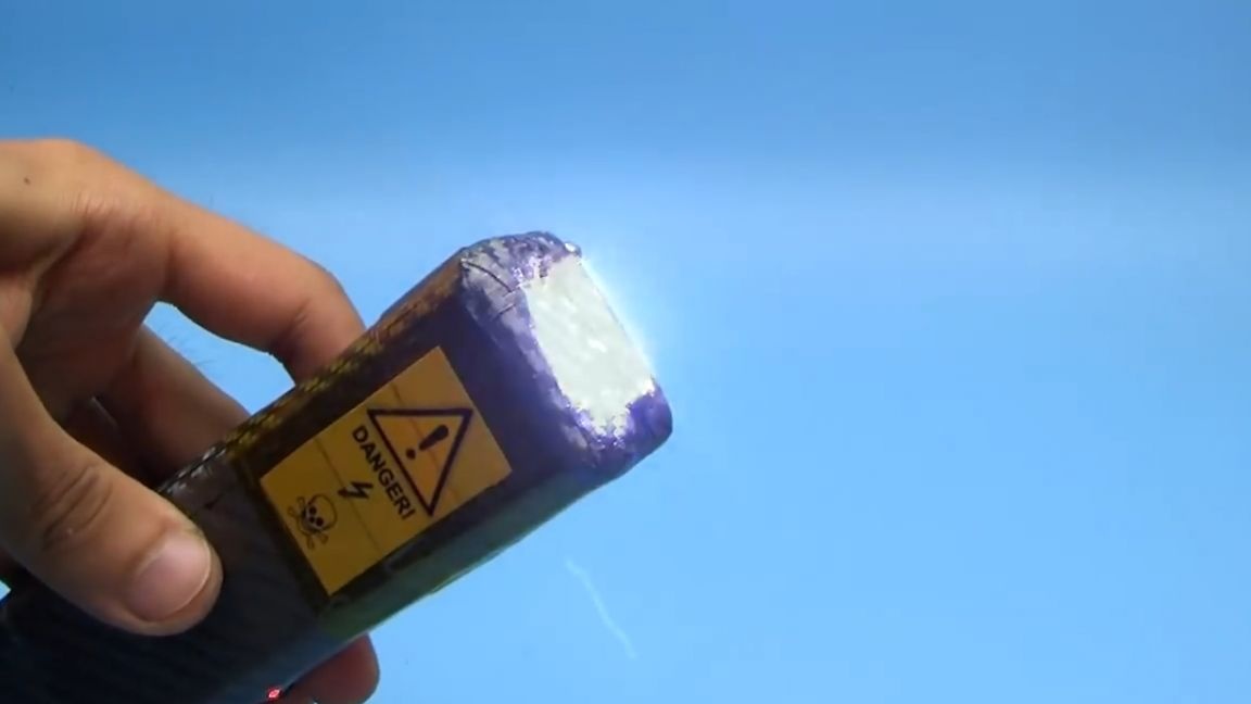
Here is an AK22X electroshock device of increased power (author AKA KASYAN).
Constructions for many years, there have been numerous modifications and improvements, namely this model was created by the author about 3 years ago and was always stored under the bed, just in case. More than one article is devoted to this stun gun (on the website of the author of the AKA KASYAN project, all links are listed under the original video of the author of this project, the SOURCE link at the end of the article), hundreds of people have successfully repeated the scheme, by the way, the scheme itself is freely available and anyone, naturally, in the presence of direct hands and some necessary knowledge in electronics can repeat it. On the author’s channel there are many videos on this topic, who are interested in the links in the description below the video. Now let's get down to business. Last year, AKA KASYAN shot a similar video on how to make a stun gun from the spare parts of an old printer, today we will continue this topic and consider the option of assembling a stun gun using components from an old economy lamp.
Gas-discharge (or energy-saving lamps) have an electronic power source or, in other words, a ballast, which is located in the lamp base. For our shocker, 2 such economy lamps are needed, but if there is, then take 3. But the lamps should be of the same power. In this case, they are at 105 watts.
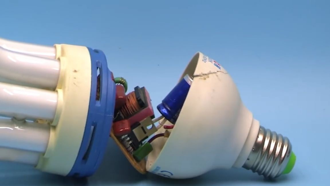
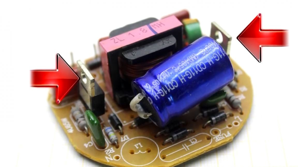
Carefully disassembling the lamp base, we get the ballast board. In fact, this is a half-bridge automatic voltage converter, which has been devoted to countless videos on YouTube. We need to disassemble both lamps. Only boards are needed, flasks can be disposed of.
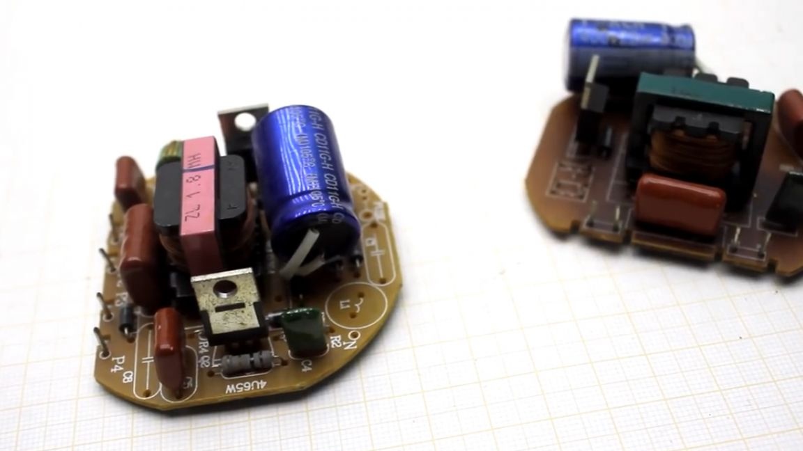
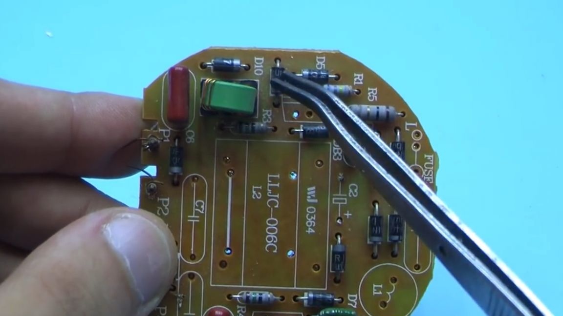
We heat the soldering iron and solder the choke first. You can’t confuse them with anything.
Next, solder the specified capacitor.
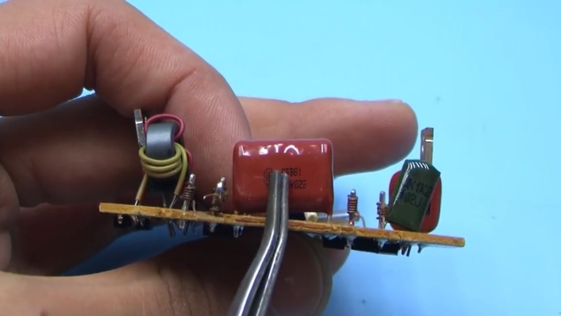

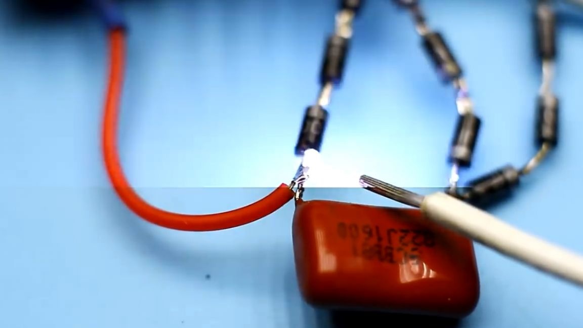
It is high-voltage with a voltage of 1000-1600 V, on each board there is only one such capacitor. Next, we solder the transistors, there are two of them, although we only need one.
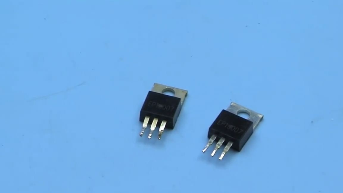
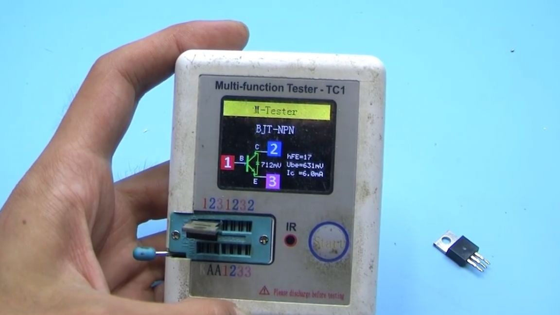
These are high voltage reverse conductivity transistors, in this case there are EP13007 keys, you can have them from the same line, it all depends on the power of the experimental lamp. Here it is necessary to indicate that the transistors must be working, they can be checked using a transistor tester or a semiconductor tester.
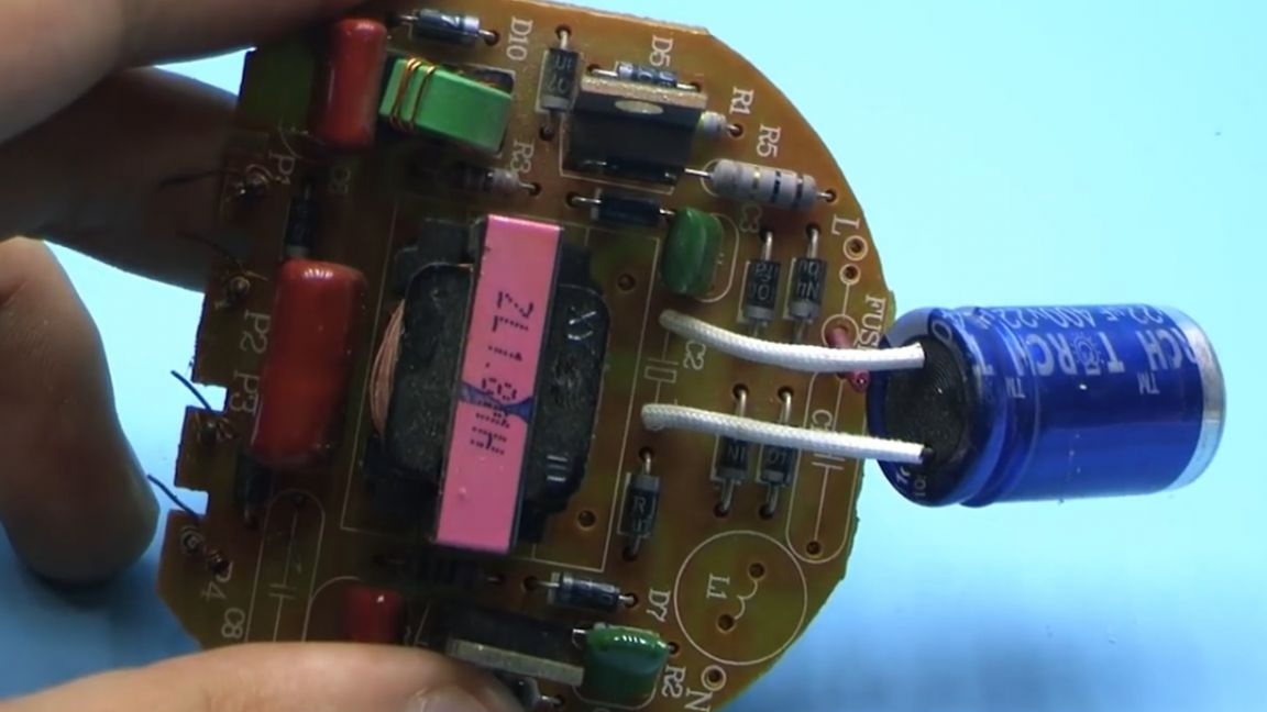
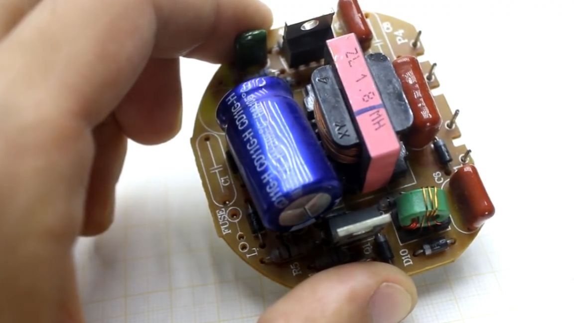
The board has a fairly large number of standard diodes.Among them, you can find several pulse diodes of the fr107 series, we find them, and we also solder them.
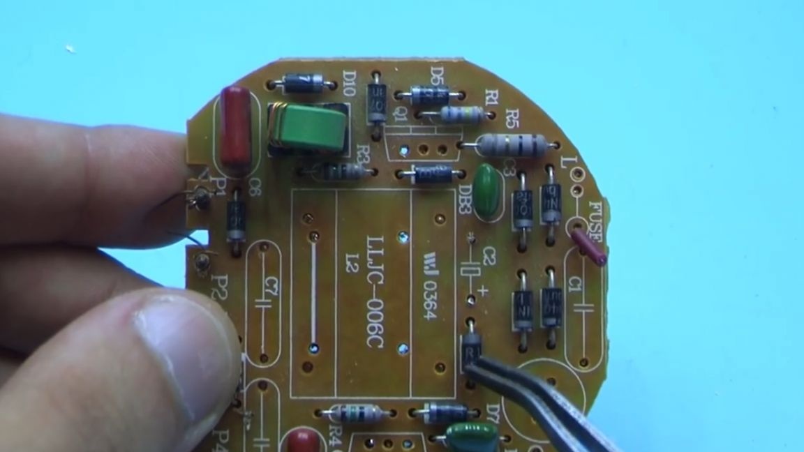
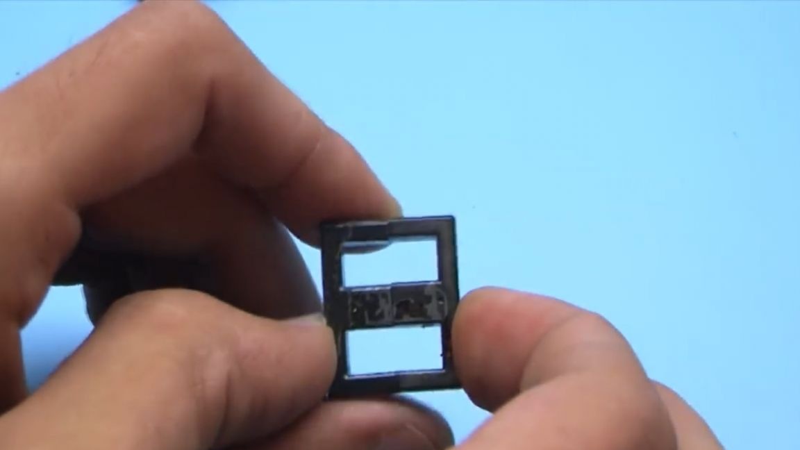
Once again, the necessary diodes are precisely marked fr107. So, with the components sorted out, go ahead. Next, we disassemble the inductor, remove the standard winding.
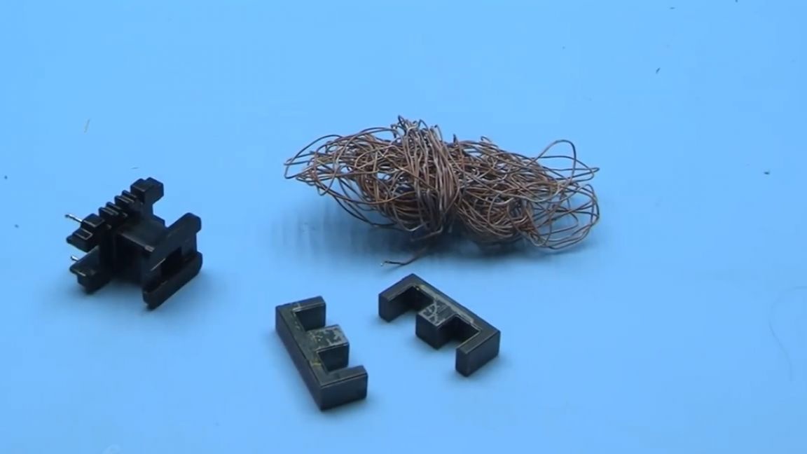
If you pay attention to the core, then between the halves you can see the gap, the central part of one of the halves of the core is shorter than the other.
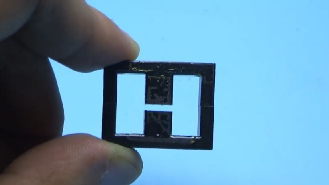
So, we have two cores, we need those halves that are longer, of which we will assemble a new transformer.
In theory, we will assemble a self-generating converter and there needs a gap, but it should be small, although the circuit will work even without a gap.
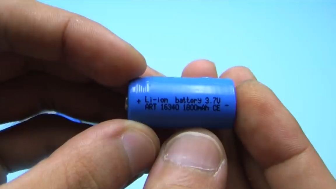
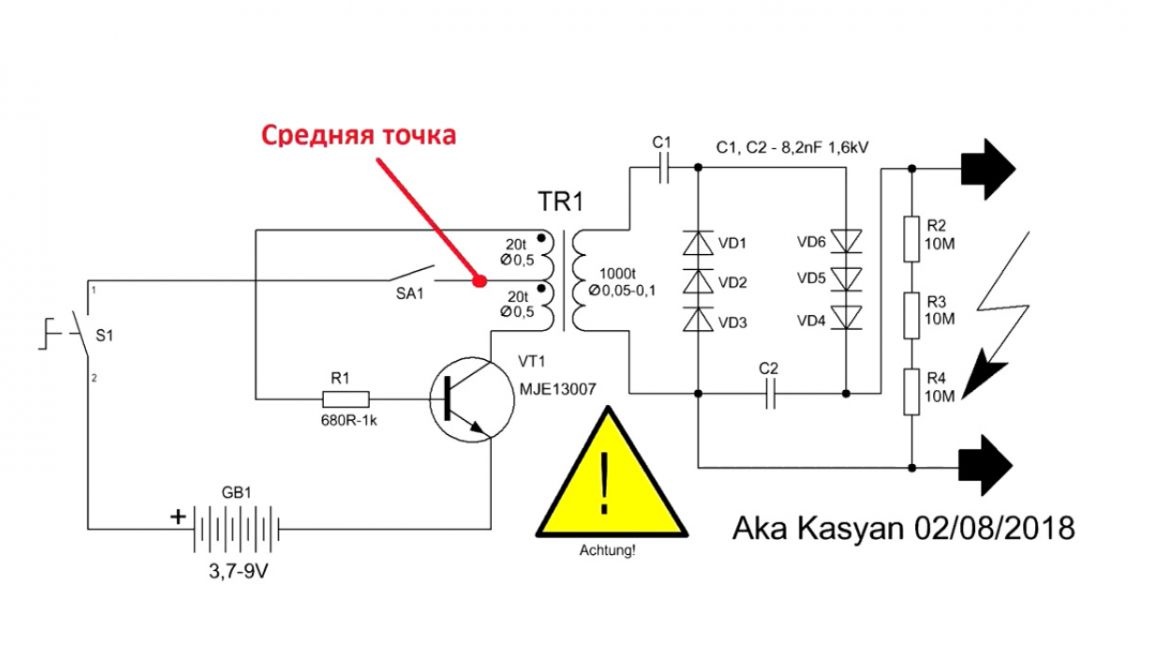
Our circuit can be powered by batteries with voltage from 3.7 to 9V. One or a pair of lithium batteries - just right.
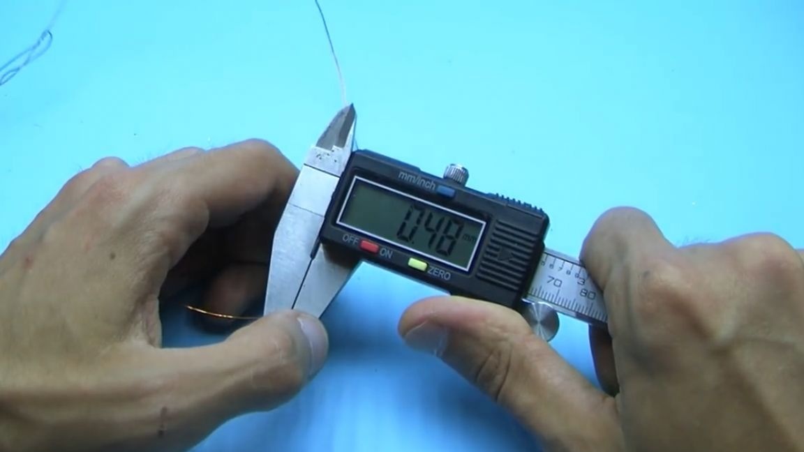
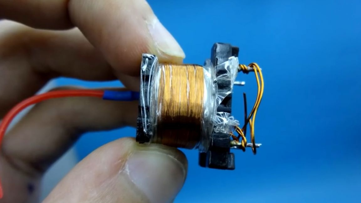
We will use the frame native, just rewind a new winding. And now, please be as careful as possible, since a detailed process of winding a high-voltage transformer will now be shown, using the technology of the author of the project, which has never failed him. To begin with, we need a wire, the diameter can be from 0.4 to 0.6 mm, more for this circuit does not make sense.
We take 2 wires, twist their ends together and start winding. The winding should contain about 20 turns. We wind in 2 rows as shown below (this is shown in more detail in the video at the end of the article).
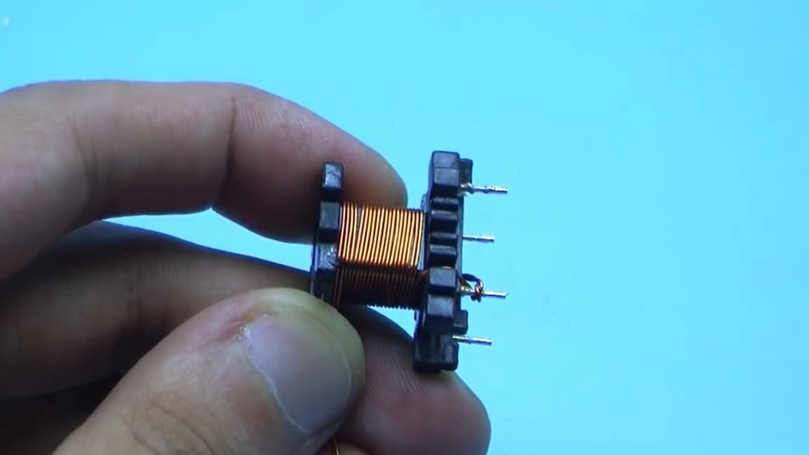
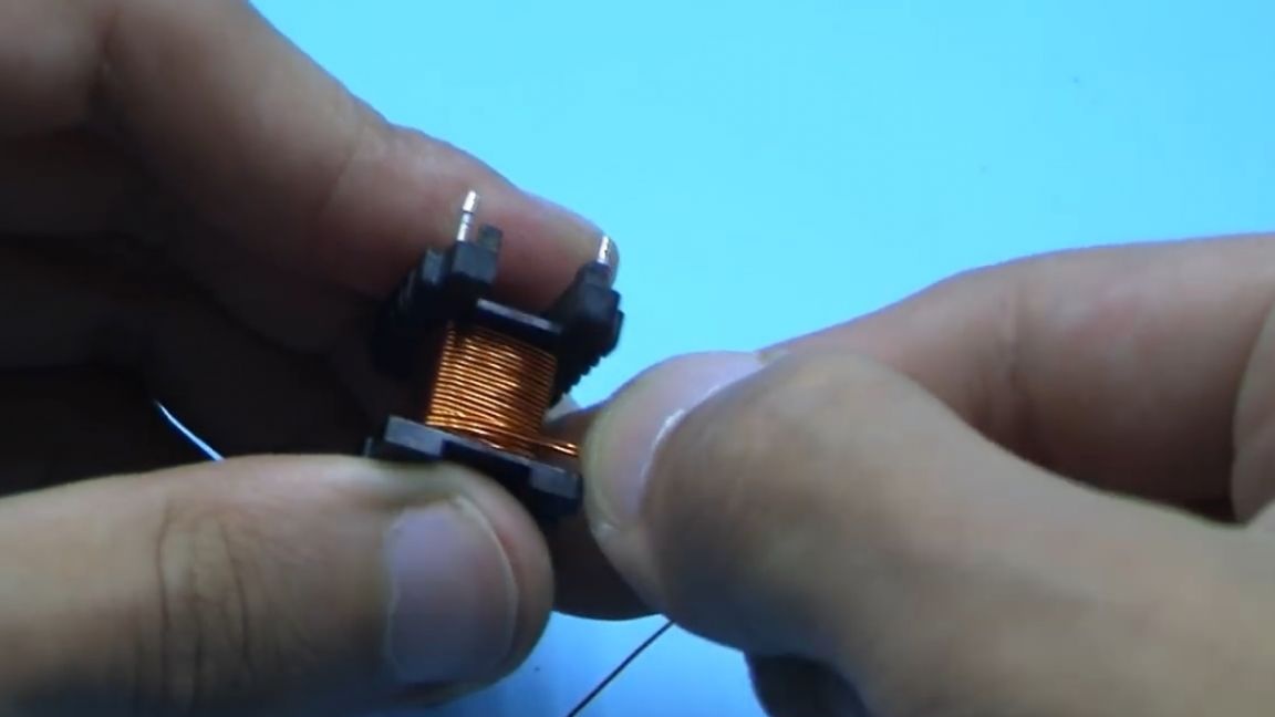
Next, we bring the end of the winding and fix it on the pin.
The next thing we take is the most ordinary, cheapest transparent tape and isolate the wound winding with ten layers of tape.

We pay special attention to isolating the tap points in the primary winding.
After winding and isolating the primary winding, we proceed to the secondary winding, it is in it that high voltage will form.
The winding consists of 800-1000 turns with a wire from 0.05 to 0.1 mm. Such a wire can be taken from a relay coil from cheap Chinese wall clocks, or bought at a radio store.
The winding of this winding is layered, each layer contains 80-100 turns. An insulation of 3 - 4 layers of adhesive tape is placed on top of the wound layer, the winding wire is never cut off, but comes with insulation.
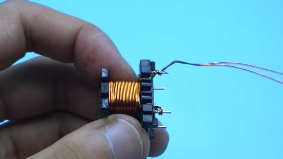
First, solder a piece of stranded wire to the winding wire, preferably in soft insulation. We hide the place of soldering under heat shrink.
We lay the secondary winding wire as evenly as possible, trying to avoid overlaps, but if they are, then it's okay.
After winding the first row, we isolate the winding. We wind the second, then again with insulation and so on until the specified number of turns is obtained.
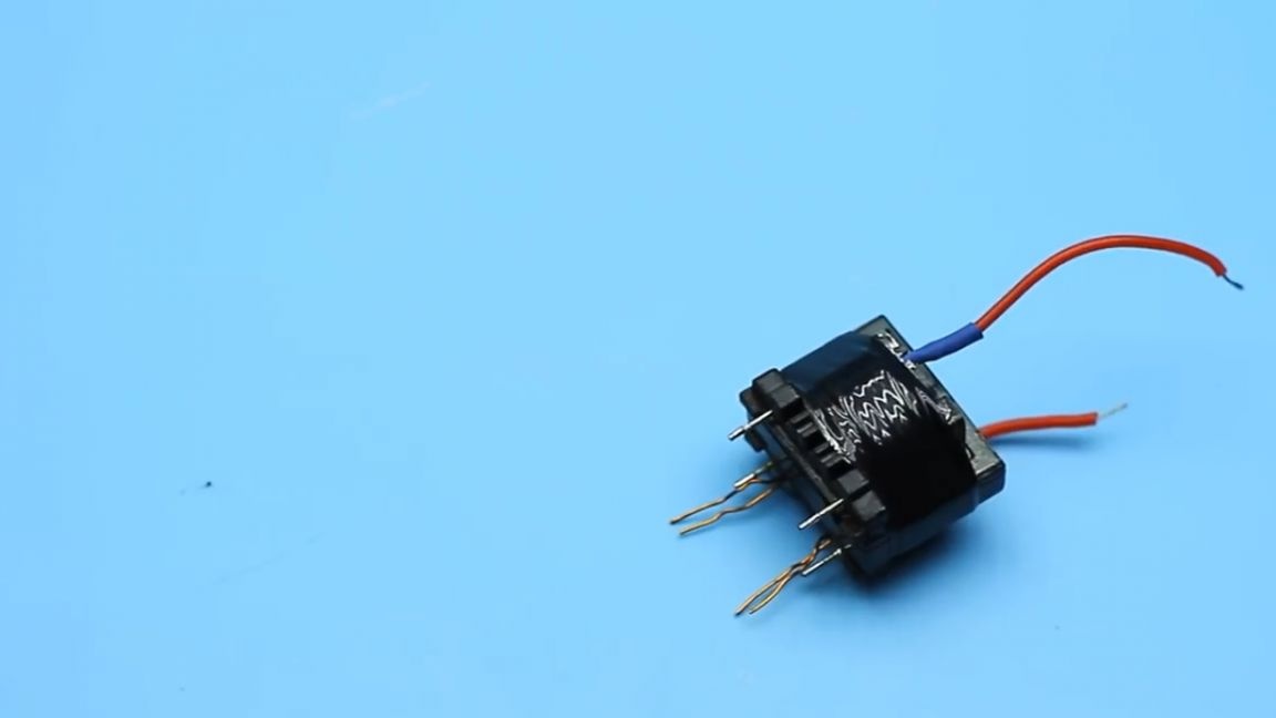
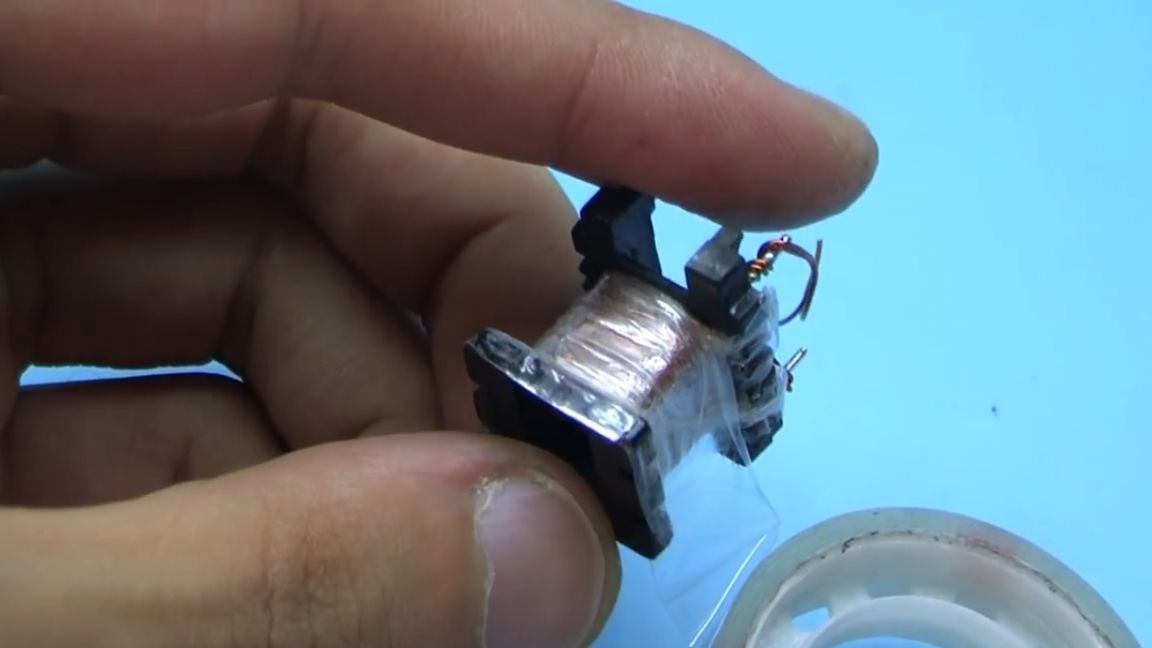
After winding is complete, we cut the wire, solder a multicore wire to it, hide the soldering place under heat shrinkage, in general, everything is as at the beginning. Next, we assemble the transformer. Halves of the core are fixed with pre-cut strips of electrical tape.
The next step is to check the secondary winding for a break. The resistance of the winding in this case is about 135 Ohms, it all depends on the number of turns and the diameter of the wire, so that you can have more or less, the main thing is that there is no break, in this case the multimeter will show infinitely large resistance.

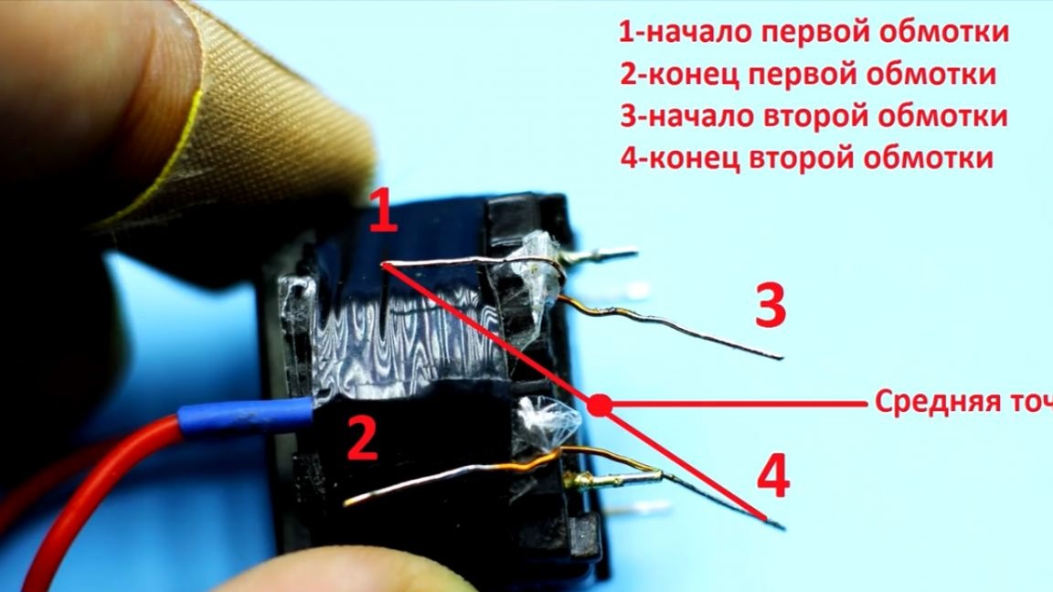
Now back to the primary winding, it needs to be phased. We connect the beginning of the first half-winding with the end of the other. If everyone was winding as the author showed, just connect the indicated conclusions to get the midpoint on the diagram, that's where the plus from the power source is fed.
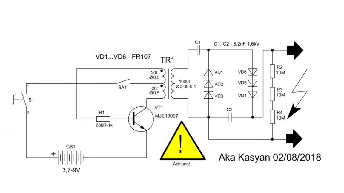
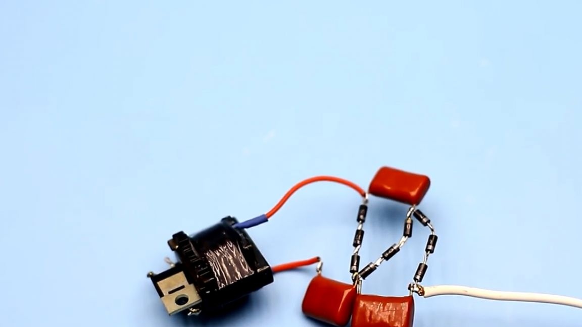
The transformer is ready, and now let's move on to the stun circuit.
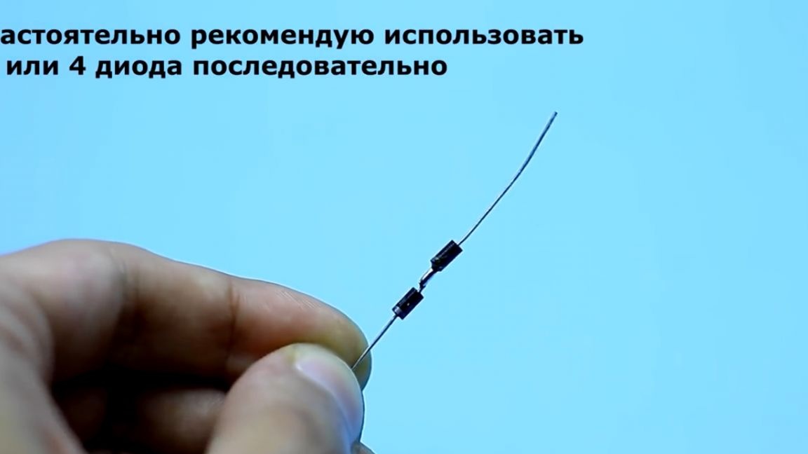
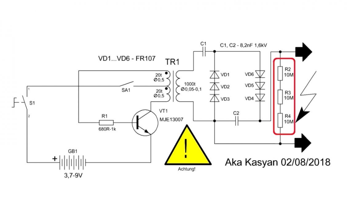
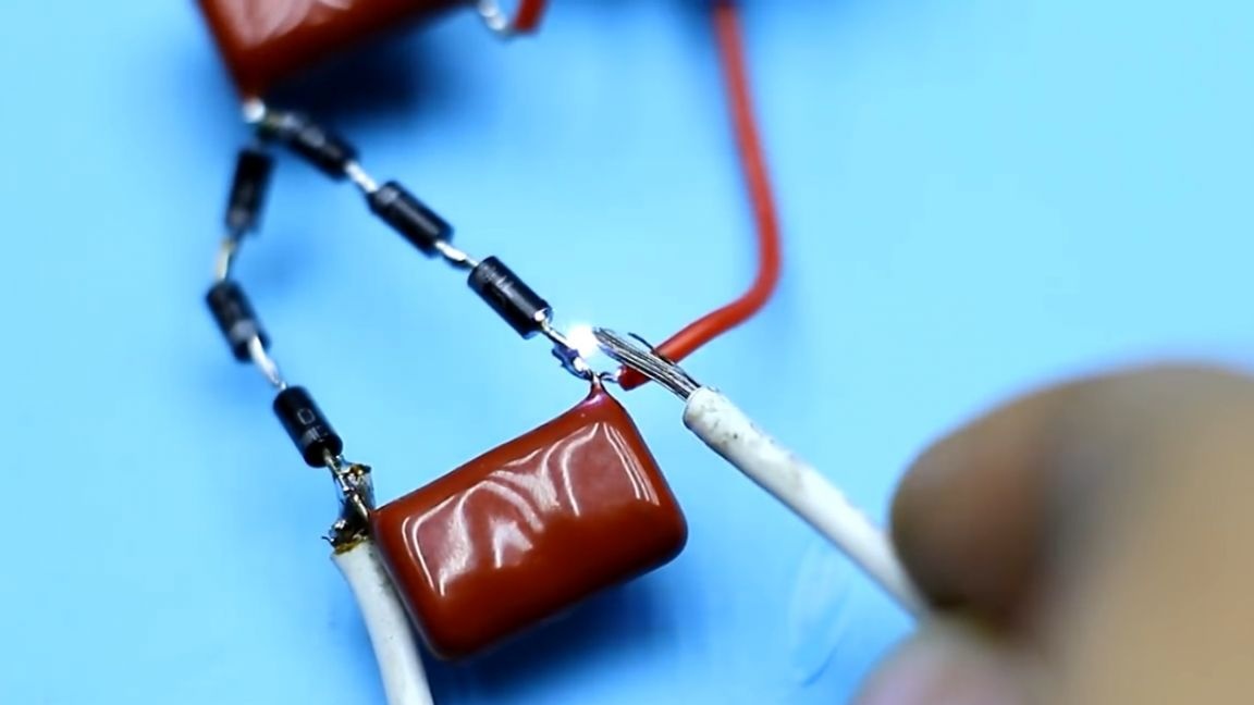
This is a high-voltage boost converter of a self-generating type. At the output there is a voltage multiplier installed on the capacitors and diodes that we previously soldered. We have a rather high voltage on the secondary winding, and fr107 diodes are only 1000V, which is why several diodes are connected in series, so we get a diode pole, the reverse voltage of which is already much larger than that of a single diode. You can connect both 2 and 3 diodes in series, as shown in the diagram.
A chain of series-connected resistors is installed at the output of the multiplier, they are needed in order to discharge the residual voltage on the capacitors of the multiplier after disconnecting the stun device.
At this stage, it is necessary to check the operation of the previously assembled transformer. To do this, collect the indicated part of the circuit.
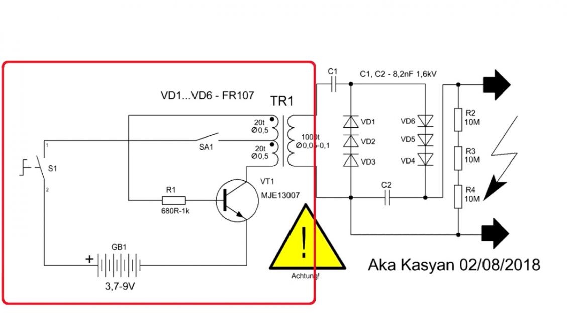
When powered by a 9 V source, the generator circuit consumes a current of only 200 mA, which is very good.
At the output of the transformer we get an alternating voltage of high frequency. It looks something like this:
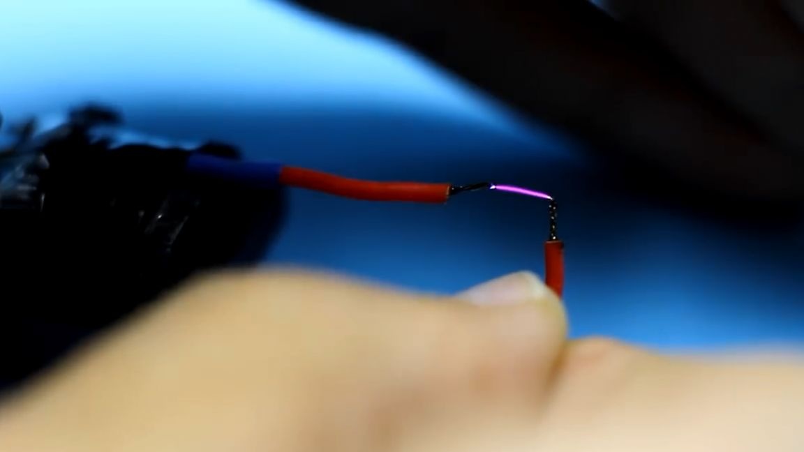
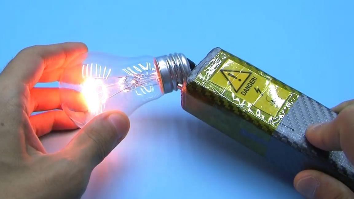
The arc extends over a sufficiently large distance, therefore, the circuit works as it should. Now it remains to assemble the multiplier, which will increase the voltage from the transformer to an even greater value.
With the multiplier connected, the discharges already look like this:
It is possible to increase the length of discharges or breakdown of air by adding a step of multiplication, but even with two capacitors the shocker pops well. Well, with three capacitors we get something abruptly:
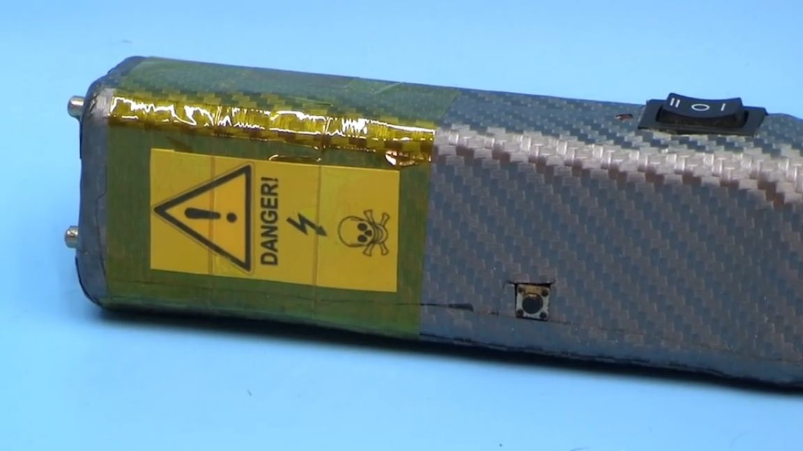
It remains only this whole thing to establish a suitable building and all. I highly advise you to fill the multiplier circuit with a high-voltage transformer with epoxy resin, or paraffin, as a last resort. How dangerous is it and can they defend themselves? Alas, for self-defense, this option is not the best because of too low output power, in addition, the breakdown of air is small. If the striker has thick clothes, then such a shocker will be useless. We are talking specifically about this stun gun, but it bites quite painfully.
Well, that’s all. See you soon!
Video: