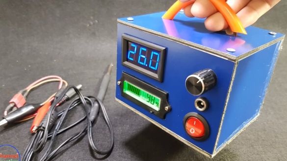
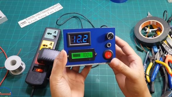
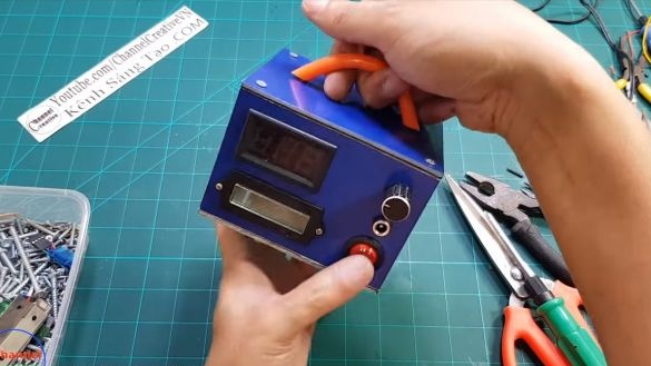
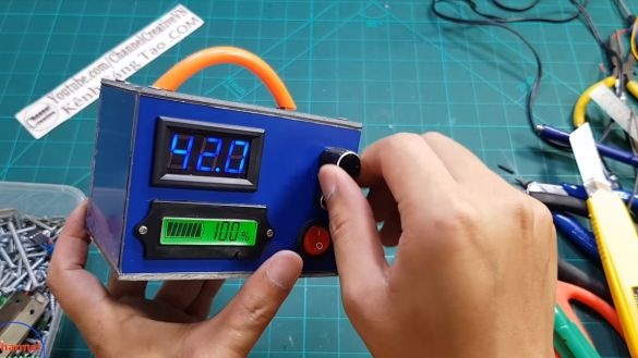
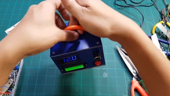
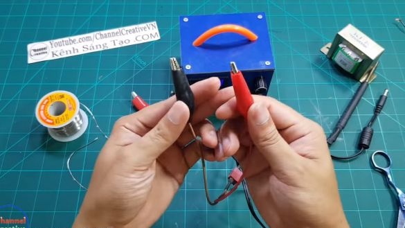
Received another new product from our Chinese master. This time he will please us with a mobile soldering station, as well as a power supply in the kit. The manufactured power supply is capable of delivering voltages from 12V to 42V, and it is powered by lithium batteries extracted from old batteries. It is convenient to take such a power supply unit with you if you need to check something or solder it out of the house, where there is no network, to connect a soldering iron and a power supply unit.
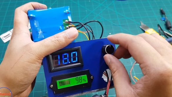
Everything is going to be quite simple. Homemade It is equipped with convenient displays that allow you to monitor the battery level, as well as the voltage that the device issues. The costs of making homemade products are also not large. So, we will consider in more detail how to assemble such a homemade product!
Materials and tools used by the author:
Material List:
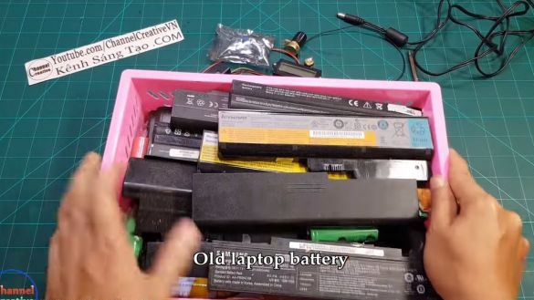
- 18650 batteries (can be obtained from old batteries);
- BMS-controller (to 18650 served longer);
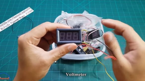
- digital voltmeter;
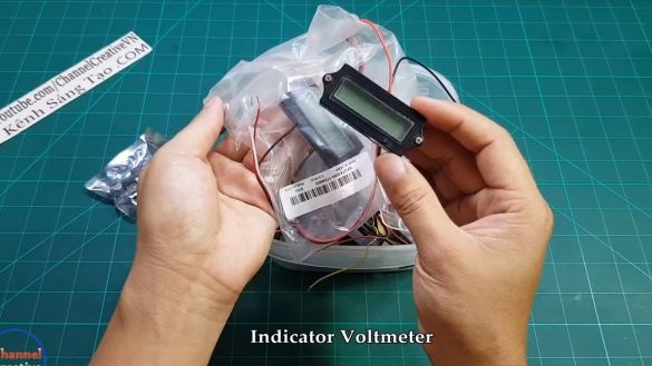
- display of the charge level (in fact, also a voltmeter with a scale);
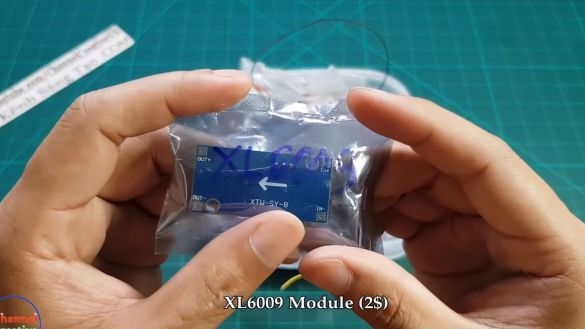
- (converter for receiving 42V from 12V);
- ;
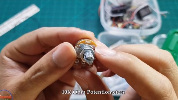
- 10K variable resistor;
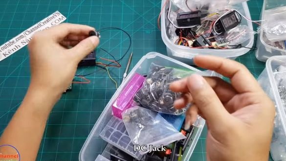
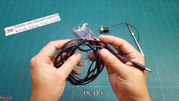
- two connectors for connecting the memory (as well as the wire from the old PSU);
- heat shrink tube (to isolate the battery);
- switch;
- wires;
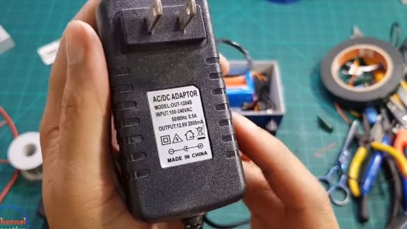
- charger 12V 2000 mA;
- double-sided adhesive tape;
- plywood or other sheet material (to make the case).
Tool List:
- spot welding machine:
- soldering iron;
- voltmeter;
- hot air gun;
- a drill.
Homemade manufacturing process:
Step one. Assembling the battery pack
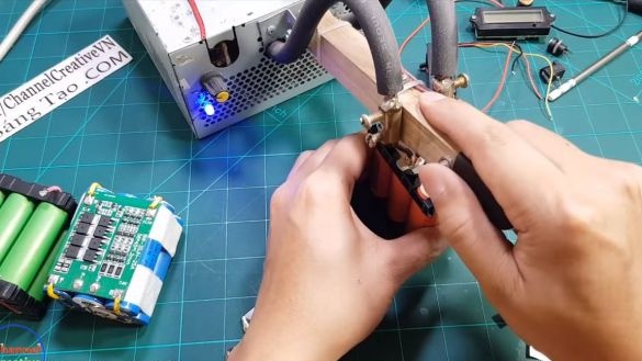
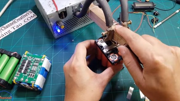
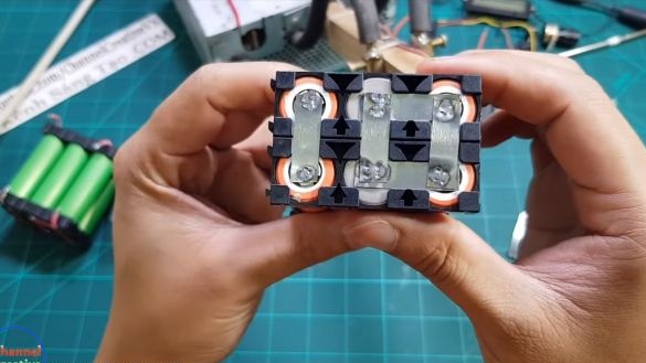
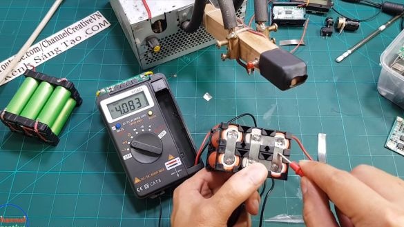
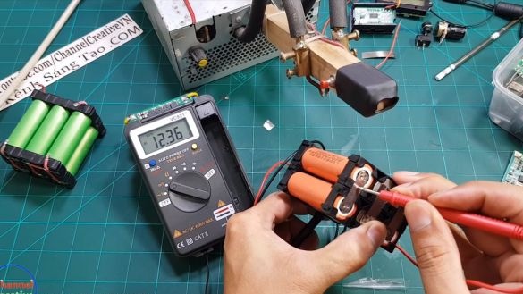
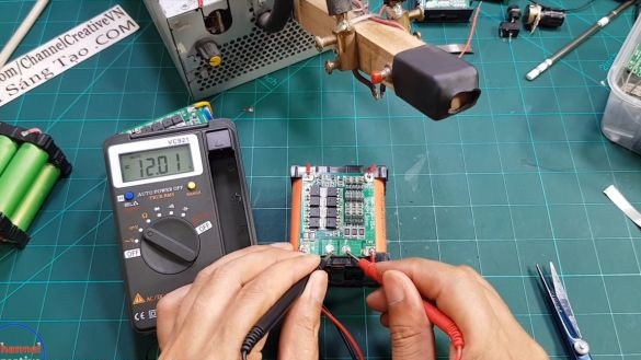
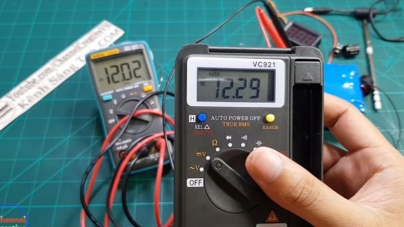
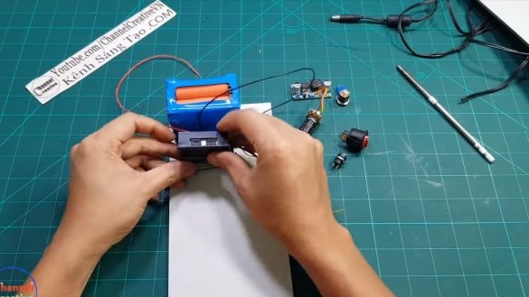
The author used batteries from an old laptop battery as a power source. In our case, these are 18650 batteries. Each such battery in a fully charged state produces a voltage of 4.2V. The author connects the batteries in such a way as to obtain a voltage of about 12.3V, in our case it is 6 cells.
The fastest and most reliable way to connect contacts is with a spot welding machine. But if this is not, you can do it with a powerful soldering iron.
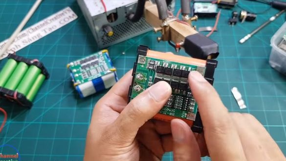
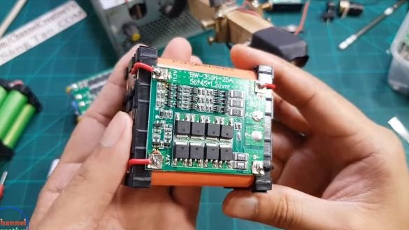
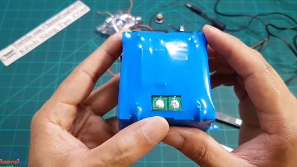
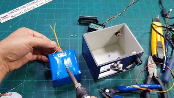
Next, we need a suitable BMS controller. Thanks to this device, you can not worry that the battery will recharge or is completely discharged. The controller itself will turn off the power supply if the voltage values exceed or fall below the threshold.Without such a controller, your batteries will very quickly fail. They can even explode if you forget to turn off the charging in time. Solder the necessary wires and fix the controller to the battery.
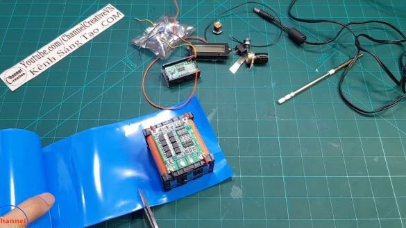
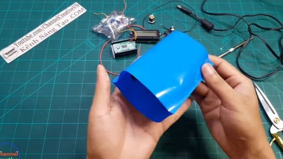
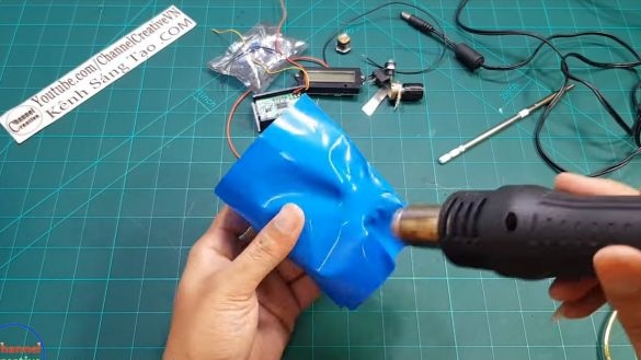
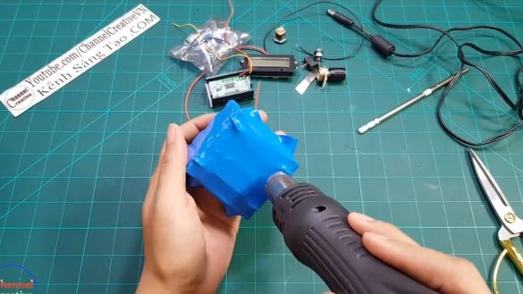
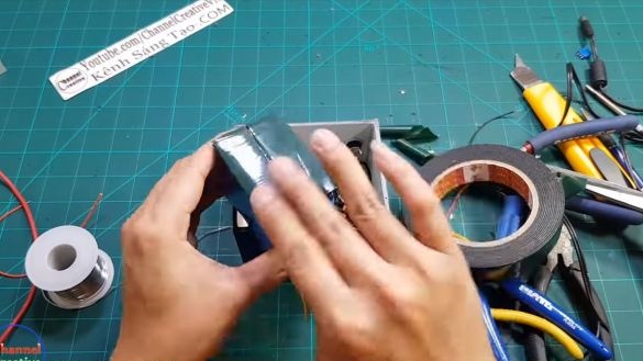
Next, we will need good insulation so that nothing goes anywhere. For these purposes, the author used a suitable diameter shrink, we plant it with a building hair dryer.
Step Two Voltage Converter Installation
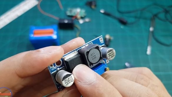
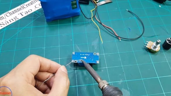
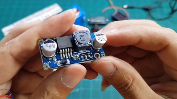
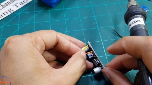
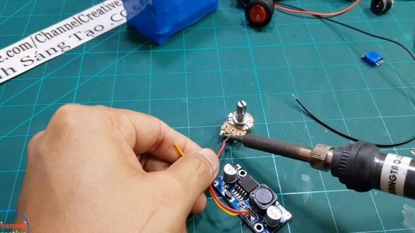
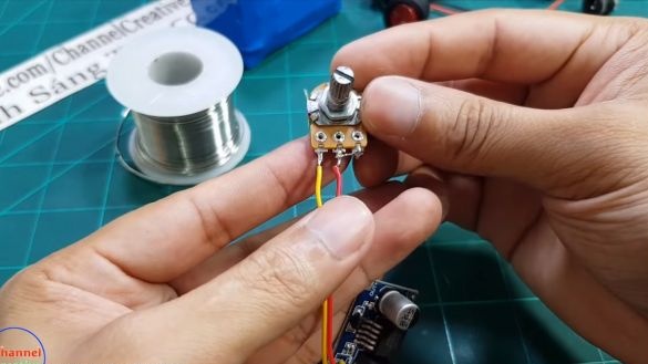
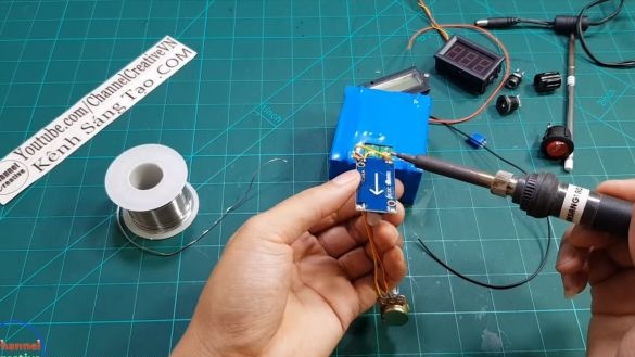
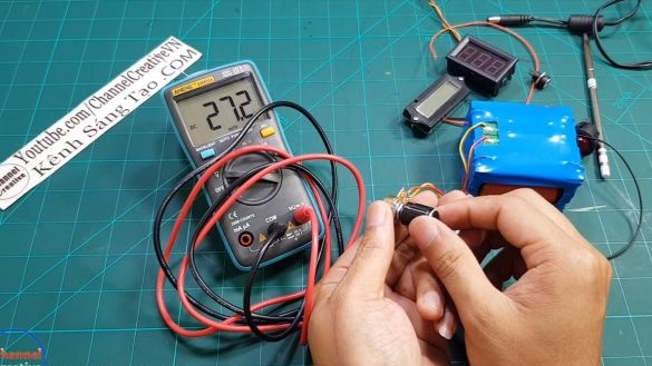
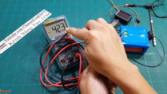
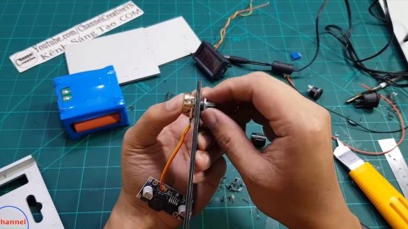
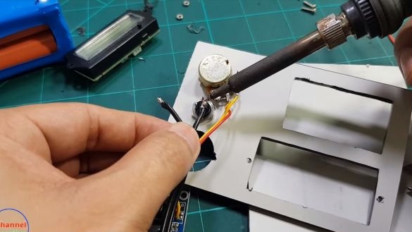
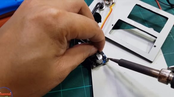
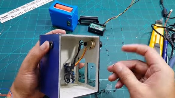
To get an adjustable power supply, you will need to install a voltage converter. In our case, this is the XL6009 module. It needs to be slightly modernized, namely, remove the standard resistor and instead solder a convenient resistor with a convenient handle that we can fix to the power supply housing. The author used a 10K variable resistor. Now with a slight twist of the knob, you can set the voltage from 12V to 42V.
Step Three Putting the case together
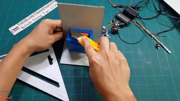
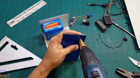
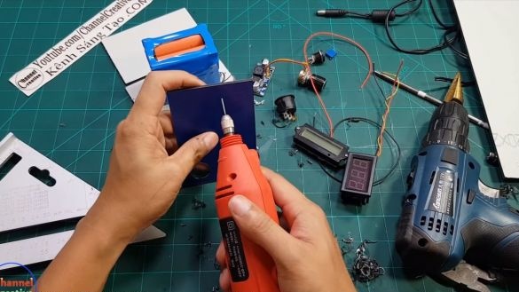
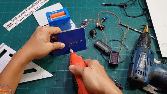
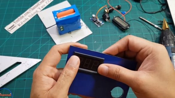
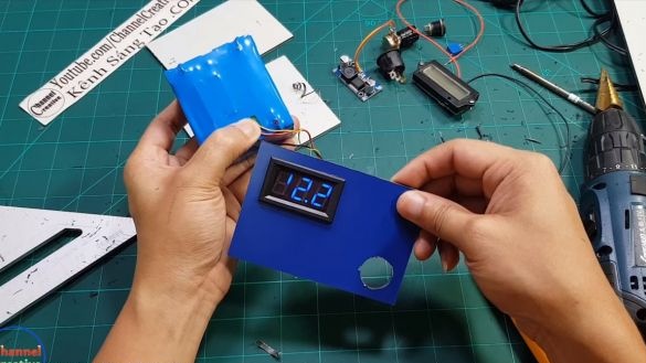
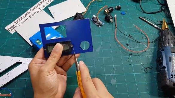
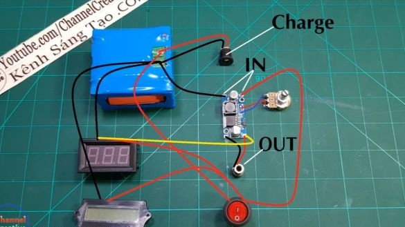
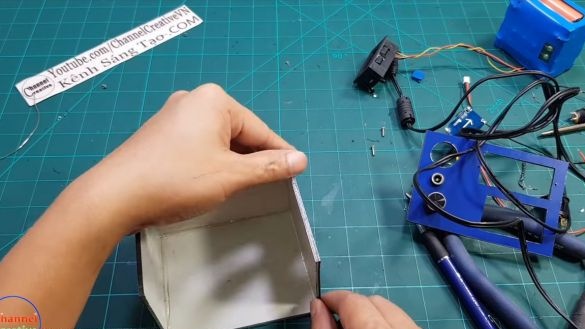
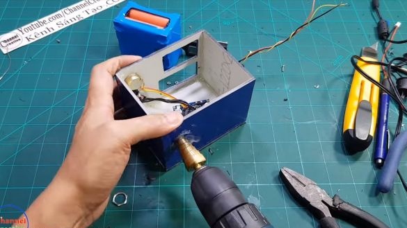
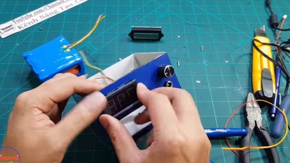
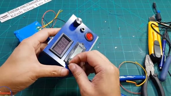
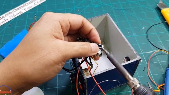
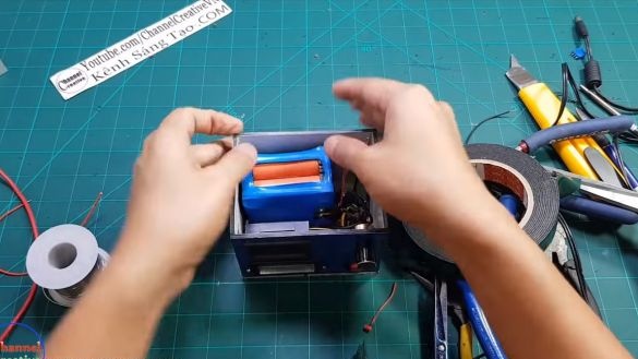
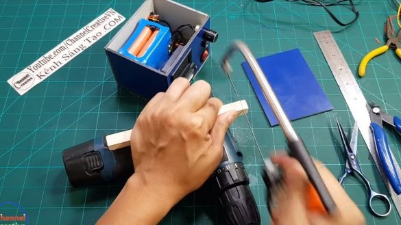
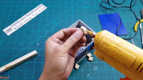
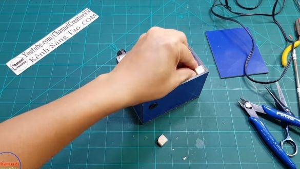
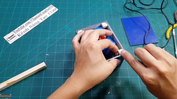
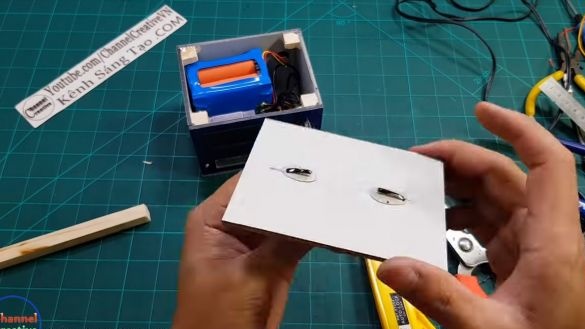
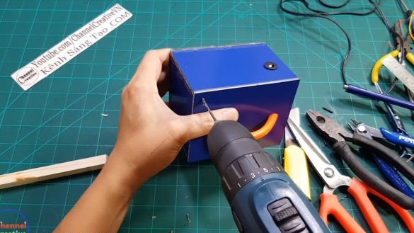
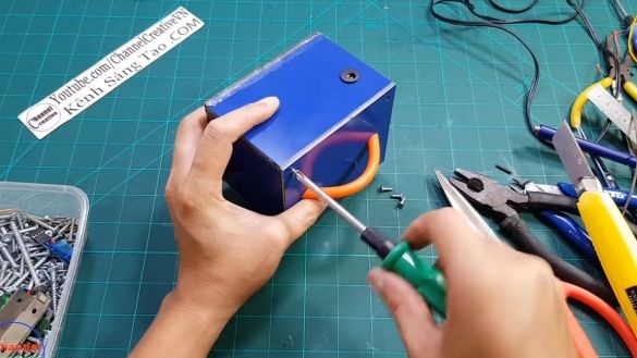
As the case, plywood, some kind of building material or something similar is suitable. We cut sheets of a suitable diameter and glue the box from them with a glue gun. We also install displays, a charging connector and a connector for connecting sources of consumption. We collect everything according to the scheme that is provided for the article.
At the end, we will need to make a cover, we fasten it with screws so that we can look inside the device if desired. The author fixes the battery with double-sided adhesive tape. Do not forget to attach a pen for convenient transfer of the device.
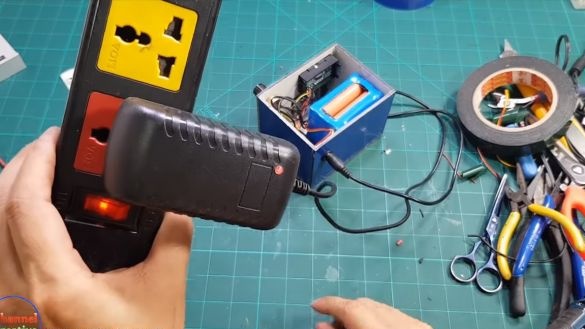
Now try to connect the charger to the device, if everything works, excellent, you can go further. The author used charging at 12.6V with a current of 2000 mA.
Step Four Making a soldering iron
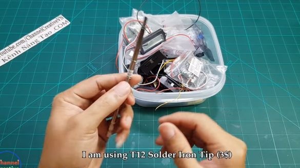
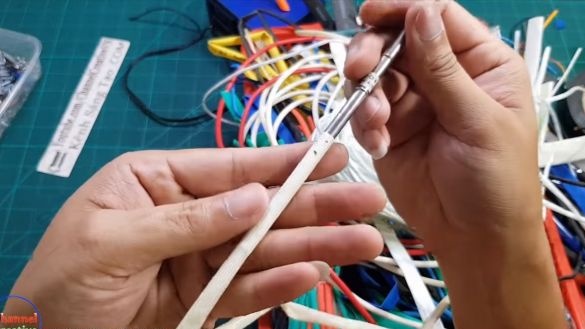
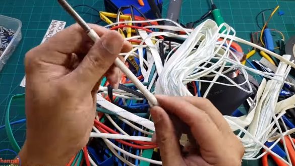
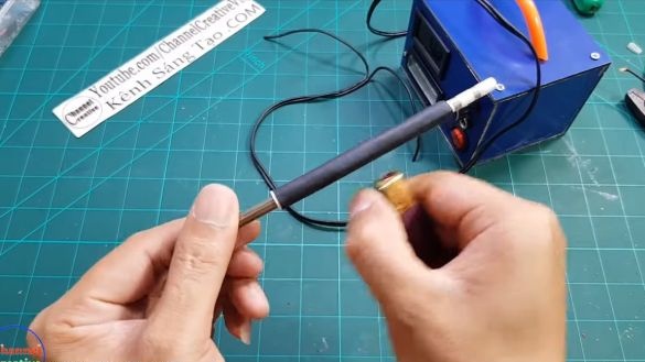
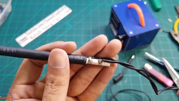
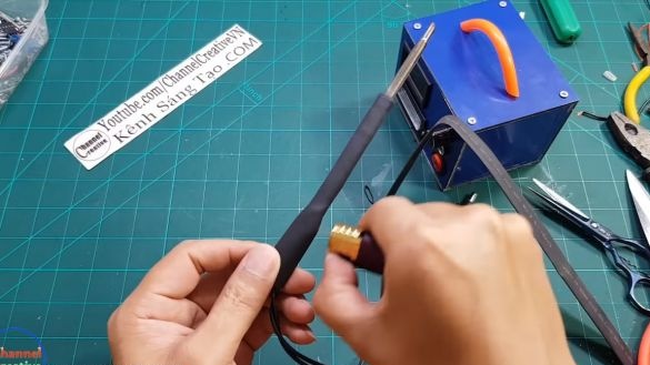
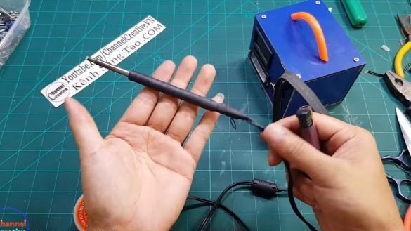
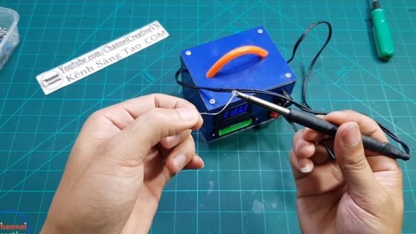
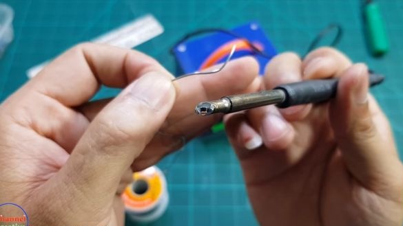
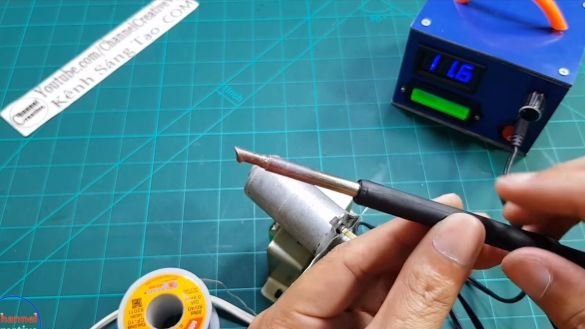
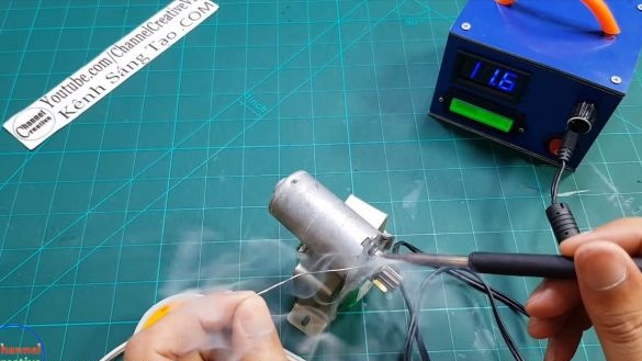
The author bought an inexpensive T12 soldering iron, which can work from a 12V power source. Solder to it the cable from the old charger with a plug. We put on a soldering iron a tube that will protect us from high temperature. And on top we also put on a heat shrink tube. Check the soldering iron in the case. To begin with, the author set the voltage to about 18V, while the soldering iron tip was heated red-hot. Then the lowest voltage was set, with it the soldering iron works optimally, it solves perfectly.
Step Five Testing device
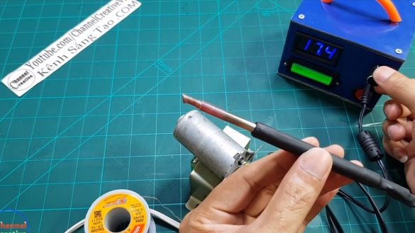
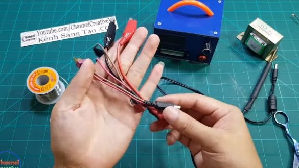
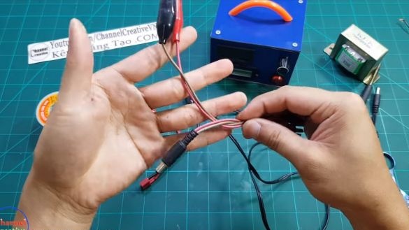
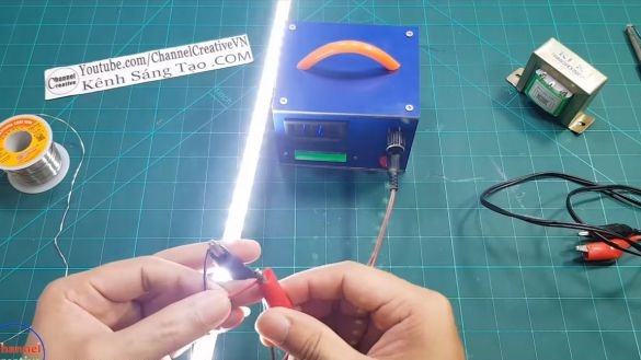
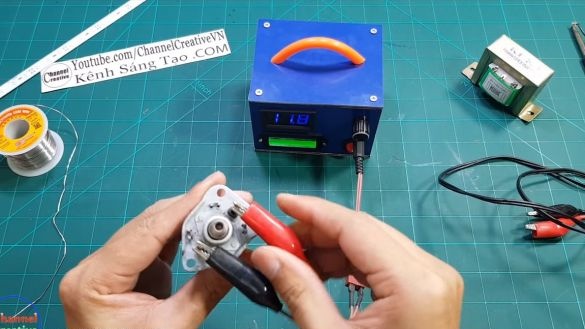
In conclusion, we need a suitable plug and crocodiles to connect the consumers we need. As an experiment, the author tried to connect an LED strip. It burns perfectly, and by adjusting the voltage, you can adjust its brightness. The DC motor also works great.
That's all, the project is over. I hope you liked the homemade product, and you found useful information for yourself. Do not forget to share your best practices and homemade products with us!

