

The development of electronics is proceeding rapidly, and more and more often the microcontroller is the main element of this or that device. He does the bulk of the work and frees the designer from the need to create sophisticated circuitry, thereby reducing the size of the circuit board to a minimum. As everyone knows, the microcontroller is controlled by a program recorded in its internal memory. And if an experienced electronic programmer does not have problems using microcontrollers in their devices, then for a beginner radio amateur trying to write a program to a controller (especially PIC) can turn out to be a big disappointment, and sometimes a small pyrotechnic show in the form of a smoking chip.
Oddly enough, but with all the greatness of the Internet, it has very little information about the firmware Pic controllers, and the material that can be found is of very dubious quality. Of course, you can buy a factory programmer for an inadequate price and sew as much as you like, but what if the person is not engaged in mass production. For these purposes, you can put together a simple and not expensive to implement homemadecalled JDM programmer according to the diagram below (figure No. 1):
Oddly enough, but with all the greatness of the Internet, it has very little information about the firmware Pic controllers, and the material that can be found is of very dubious quality. Of course, you can buy a factory programmer for an inadequate price and sew as much as you like, but what if the person is not engaged in mass production. For these purposes, you can put together a simple and not expensive to implement homemadecalled JDM programmer according to the diagram below (figure No. 1):
Figure №1 - diagram of the programmer
Immediately I bring a list of elements for those who are too lazy to peer into the diagram:
- R1 - 10 kOhm
- R2 - 10 kOhm (truncated). By adjusting the resistance of this resistor, you need to achieve about 13V at pin No. 4 (VPP) during programming. In my case, the resistance is 1.2 kOhm
- R3 - 200 ohms
- R4, R5 - 1.5 kOhm
- VD1, VD2, VD3, VD4, VD6 - 1N4148
- VD5 - 1N4733A (Stabilization voltage 5.1V)
- VD7 - 1N4743A (Stabilization voltage 13V)
- C1 - 100 nF (0.1 μF)
- C2 - 470 μF x 16 V (electrolytic)
- SUB-D9F - COM port connector (MOM or SOCKET)
- DIP8 socket - depends on the controller you use
The circuit uses an example of connecting such common controllers as PIC12F675 and PIC12F629, but this does not mean at all that the firmware of other series Pic will be impossible. To write a program to a controller of a different type, it is enough to transfer the programmer wires in accordance with Figure 2, which is given below.
Figure 2 - PIC controller case options with the necessary conclusions
As you might guess, the case is used in the scheme of my programmer Dip8. With a great desire, you can make a universal adapter for each type of chip, thereby obtaining a universal programmer. But since with PIC controllers I rarely work, that's enough for me.
Although the circuit itself is quite simple and does not cause difficulties in assembly, but it also requires respect. Therefore, it would be nice to make a printed circuit board for it. After some manipulations with the program Sprintlayout, textolite, drill and iron, such a blank was born here (photo No. 3).
Although the circuit itself is quite simple and does not cause difficulties in assembly, but it also requires respect. Therefore, it would be nice to make a printed circuit board for it. After some manipulations with the program Sprintlayout, textolite, drill and iron, such a blank was born here (photo No. 3).
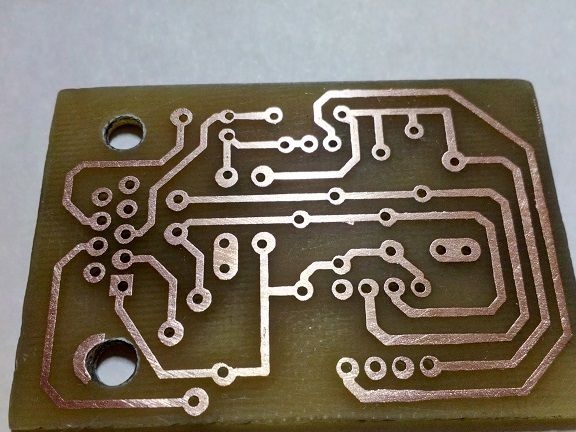
Photo No. 3 - programmer circuit board
Download PCB source for the program Sprintlayout You can follow this link:
If desired, you can change it to your type of PIC controller. For those who decided to leave the board unchanged, I spread the view from the side of the parts to facilitate installation (Figure 4).
If desired, you can change it to your type of PIC controller. For those who decided to leave the board unchanged, I spread the view from the side of the parts to facilitate installation (Figure 4).
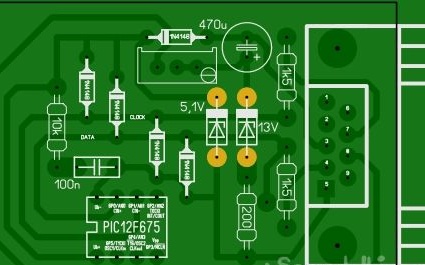
Figure 4 - Board on the mounting side
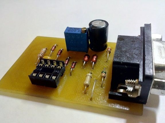
A little more witchcraft with a soldering iron and we have a ready-made device that can flash Pic controller through COM port your computer. Still warm and not washed from the flux, the result of my efforts is shown in photo No. 5.
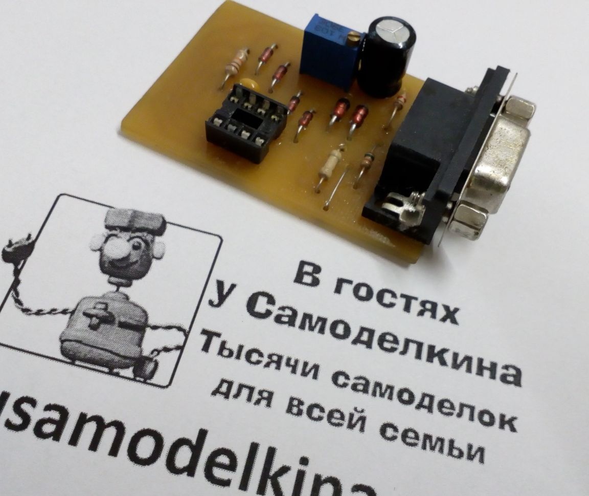
Photo No. 5 - complete programmer
From now on, the first step towards firmware Pic controllercame to an end. The second stage will include connecting the programmer to the computer and working with the program IC Prog.
Unfortunately, not all modern computers and laptops are able to work with this programmer due to the banal absence on them COM ports, and those that are installed on laptops do not give out the necessary programming 12V. So I decided to turn to my first PCwho long ago dusted and waited for his finest hour (and still waited).
So turn on the computer and first install the program IC Prog. You can download it from the author’s site or at this link:
We connect the programmer to COM port and run the newly installed application. For correct operation, it is necessary to perform a series of manipulations. Initially, it is necessary to choose the type of controller that we are going to sew. I have it PIC12F675. In screenshot # 6, the field for selecting the controller is highlighted in red.
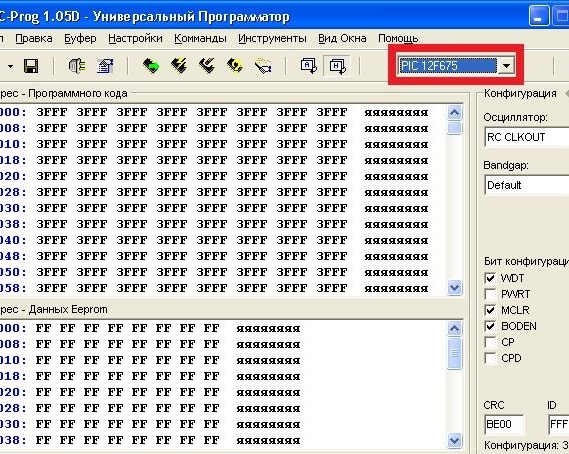
Screenshot 6 - microcontroller type selection
Next, go to the menu "Settings "->" Options", in the window that appears, select the tab I2C and check the boxes as shown in screenshot # 7.
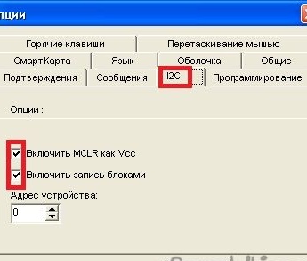
Screenshot 7 - setting the controller recording method
In the same window, go to the tab "Programming"and select"Programming Check". Checking after programming may cause an error, because in some cases the firmware installs lock fuses SR. In order not to fool yourself, it is better to disable this check. In short, follow the screenshot number 8.
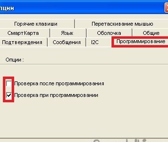
Screenshot No. 8 - verification setup
We continue to work with this window and go to the "Are common". Here it is necessary to set the priority of the program and be sure to use NT / 2000 / XP driver (screenshot number 9). In some cases, the program may suggest the installation of this driver and may require a restart IC Prog.
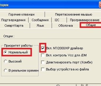
Screenshot 9 - General Settings
So, with this window the work is over. Now let's move on to the settings of the programmer itself. Choose in the menu "Settings "->" Programmer Settings"or just press the key F3. The following window appears, shown in screenshot # 10.
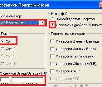
Screenshot No. 10 - programmer settings window
First of all, select the type of programmer - Jdm programmer. Next, we set the radio button for using the driver Windows. The next step is to choose COM portwhich your programmer is connected to. If there is one, there are no questions at all, and if there is more than one, look in the device manager which is currently being used. The input / output delay slider is designed to control the speed of writing and reading. This may be needed on fast computers and if there are problems with the firmware - this parameter must be increased. In my case, it remained by default equal to 10 and everything worked fine.
On this program setting IC Prog is over and you can proceed to the process of the firmware itself, but first we read the data from the microcontroller and see what is written into it. To do this, on the toolbar, click on the icon of the microcircuit with a green arrow, as shown in screenshot No. 11.
On this program setting IC Prog is over and you can proceed to the process of the firmware itself, but first we read the data from the microcontroller and see what is written into it. To do this, on the toolbar, click on the icon of the microcircuit with a green arrow, as shown in screenshot No. 11.
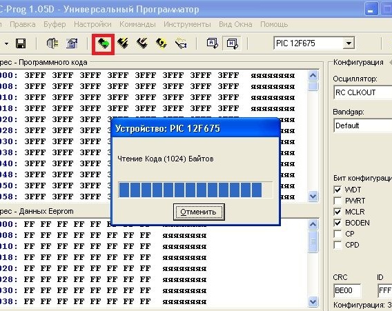
Screenshot 11 - The process of reading information from the microcontroller
If the microcontroller is new and has not been flashed before, then all its memory cells will be filled with values 3FFFexcept the very last one. It will contain the value of the calibration constant. This is a very important and unique value for each controller. The accuracy of the clock depends on it, which is selected by the manufacturer by selecting and installing this constant. The screenshot No. 12 shows the memory cell in which the constant will be stored when reading the controller.
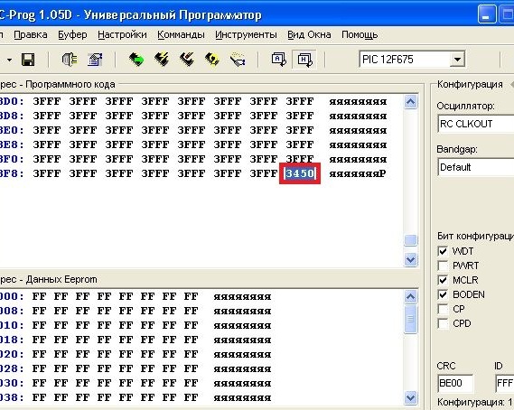
Screenshot 12 - value of the calibration constant
I repeat that the value is unique for each microcircuit and does not have to coincide with what is shown in the figure. Many by inexperience overwrite this constant and subsequently Pic controller starts to work incorrectly if the project uses clocking from an internal generator. I advise you to write down this constant and stick the inscription with its value directly on the controller. This way you will avoid a lot of trouble in the future. So, the value is written down - we move on. Open the firmware file, which usually has an extension .hex. Now instead of writing 3FFF, the programming buffer contains the code of our program (screenshot No. 13).
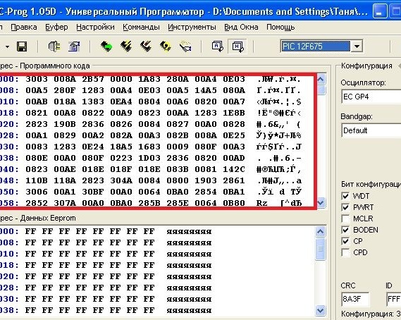
Screenshot 13 - firmware downloaded to the programming buffer
I wrote above that many overwrite the calibration constant by negligence. When does this happen? This happens when the firmware file is opened. The value of the constant automatically changes to 3FFF and if you start the programming process, then there is no turning back. In screenshot No. 14, that memory cell where the constant was previously 3450 (before opening hex file).
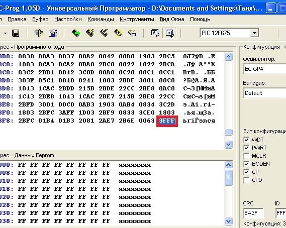
Screenshot No. 14 - automatic change of calibration constant
Now you need to carefully follow the steps below. We click on the icon of the microcircuit with lightning on the toolbar, thereby informing the program that we want to initiate the firmware process. The program will ask if we are sure that we want to flash this device. We agree and click "YES". After that, we get the warning shown in screenshot # 15.
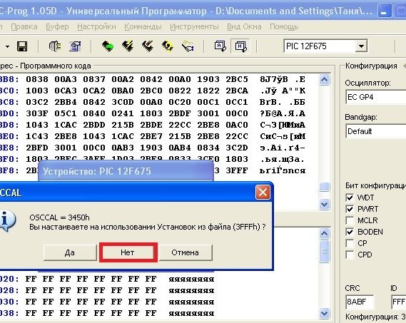
Screenshot No. 15 - warning about discrepancy in the values of the clock constant
IC Prog tells us that one value of the calibration constant (in my case 3450), and now another (3FFF) automatically substituted from hex file. It is also proposed to leave the default value 3FFF. It’s important to click "NOT"to IC Prog during programming returned us the value 3450 or what will be with you. In general, click "NOT"and observe the following window (screenshot No. 16).
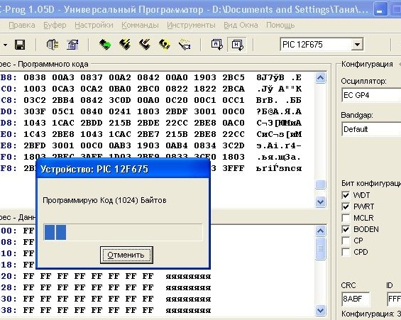
Screenshot 16 - programming process
During this period, I advise you not to press anything or load the computer with other tasks. When I took a screenshot for this article, when I click on the button Print screen a write error occurred and I had to do it all over again. After some time IC Prog will give you a message about the successful verification of the newly written code in your Pic controller, so everyone who liked this article, I want to see this after similar efforts (screenshot No. 17):
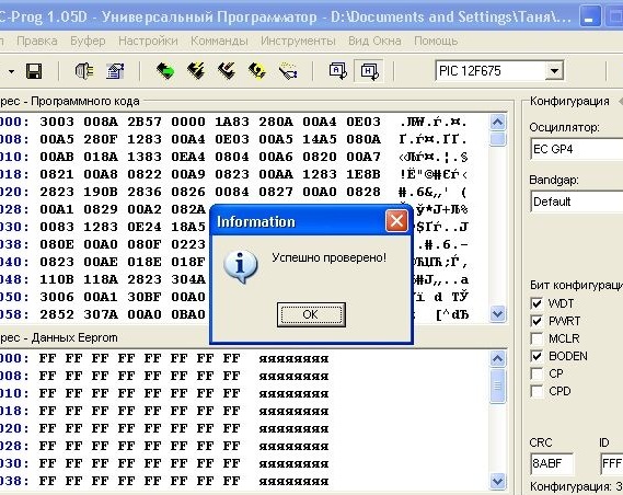
Screenshot No. 17 - the firmware was successful, you can relax
If in the process you have any questions, carefully re-read the article again and everything will surely work out - checked personally. Good luck to everyone and creative success !!!