
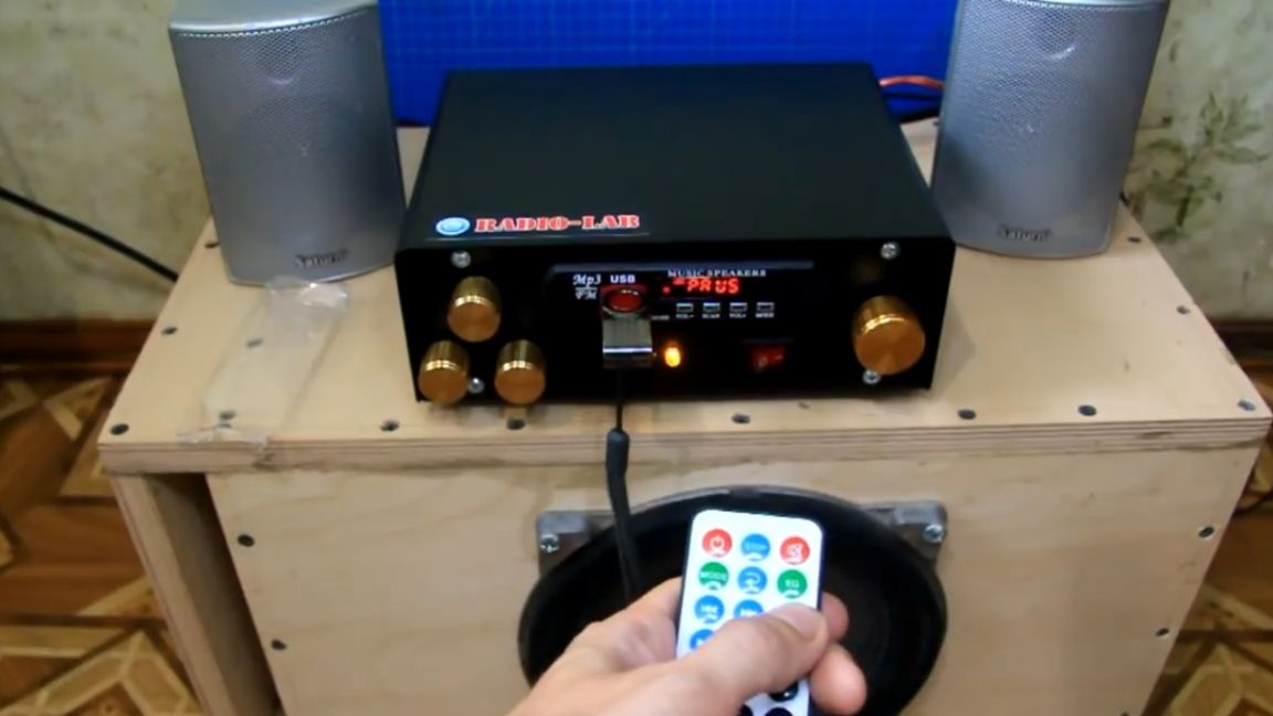
The author of the Radio-Lab channel decided to build a budget 2.1 audio system with a subwoofer and a sound module.
This article is about this homemade product and will be discussed. The author decided to assemble an audio system from those components that had previously been unused. Such a case will be used as a block of a sound amplifier. This was one of the author’s early projects - a quad, which he changed his mind about collecting further.
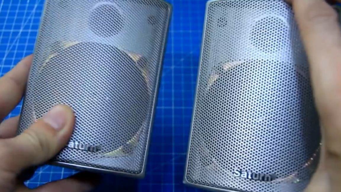
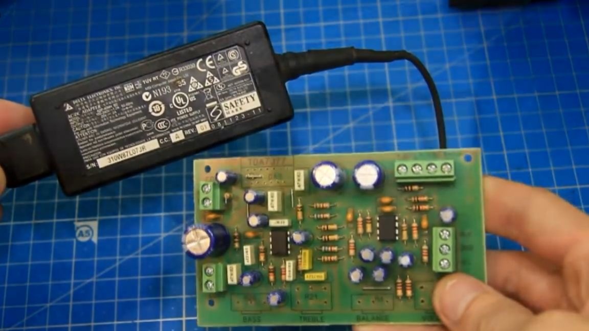
In general, it will be the case of the future amplifier, especially since almost everything is ready, you just need to rebuild the inside. The speakers for future satellites will be like that, left over from the Saturn home theater. The power supply was like this from an MSI laptop with the following characteristics: voltage 20 V, current 2A. Its power is enough to power the future amplifier.
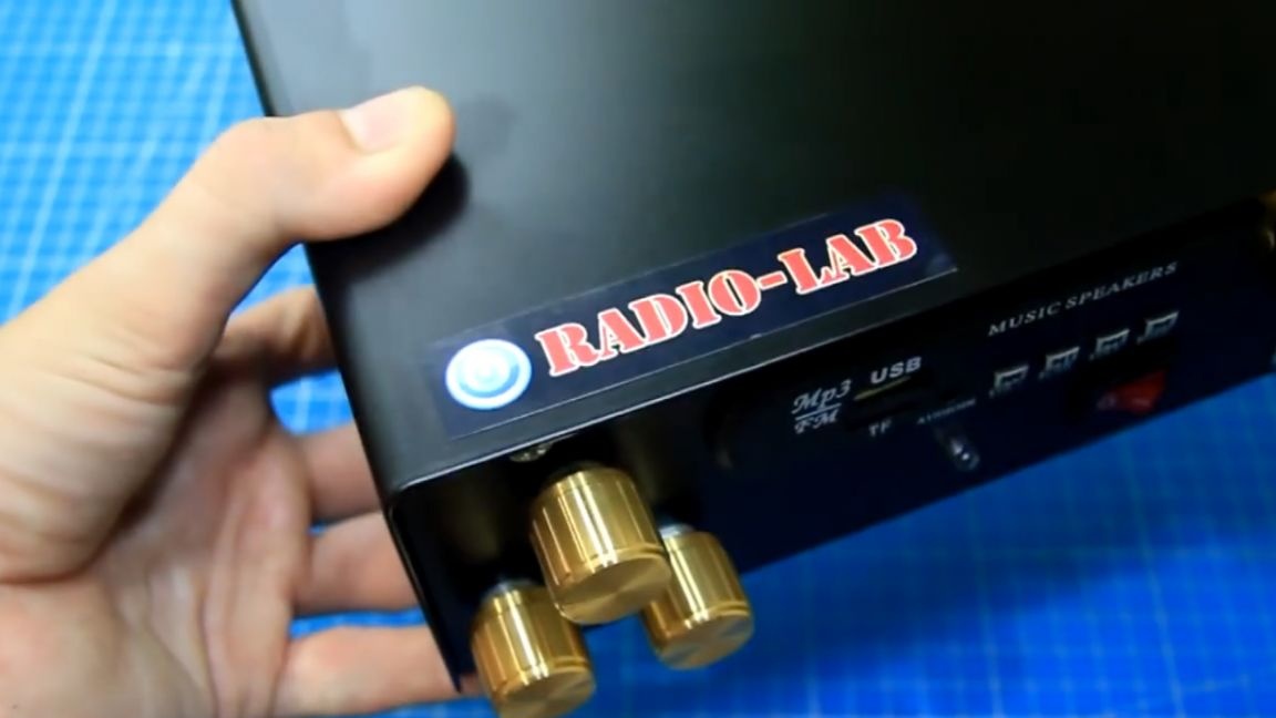
The author assembled the subwoofer himself on the basis of the speaker 35gdn. The subwoofer is passive, does not have an internal amplifier. The drawing was found by the author on the Internet, below you can also familiarize yourself with it.
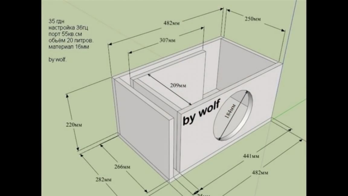
The case was assembled for PVA glue, on the advice of friends. Well, outwardly it looks like this:
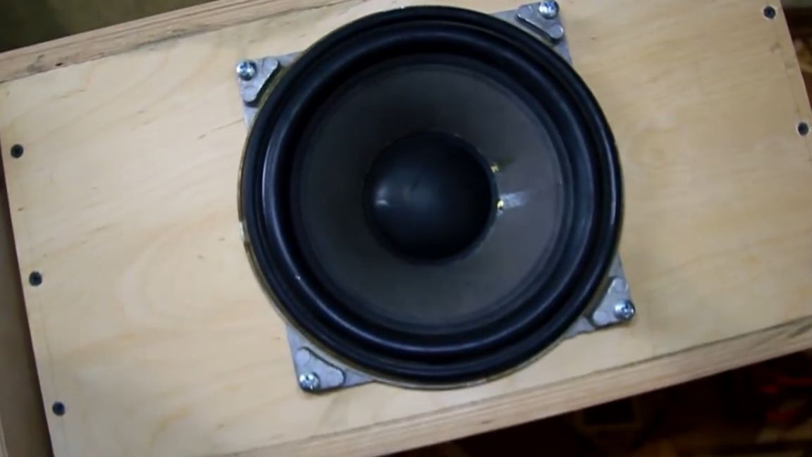
It does not affect the quality of the bass. Bass subwoofer quality and powerful. The author did not even expect such a high-quality bass from an old 35gdn.
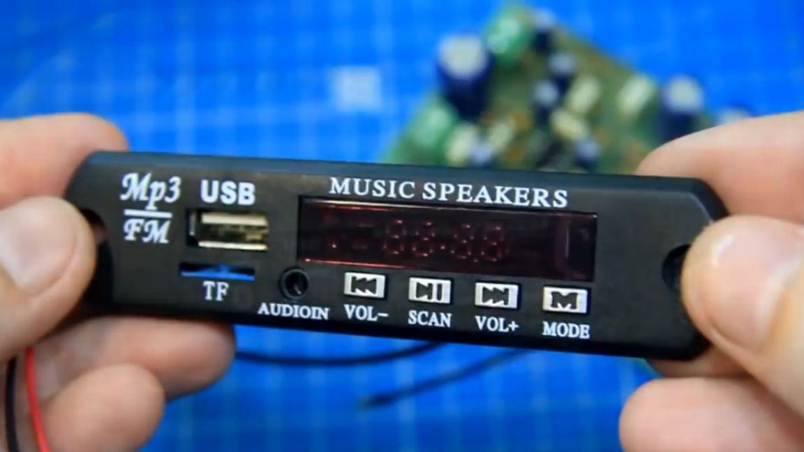
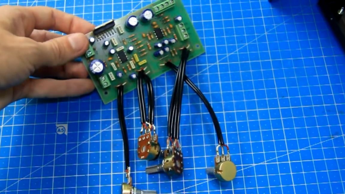
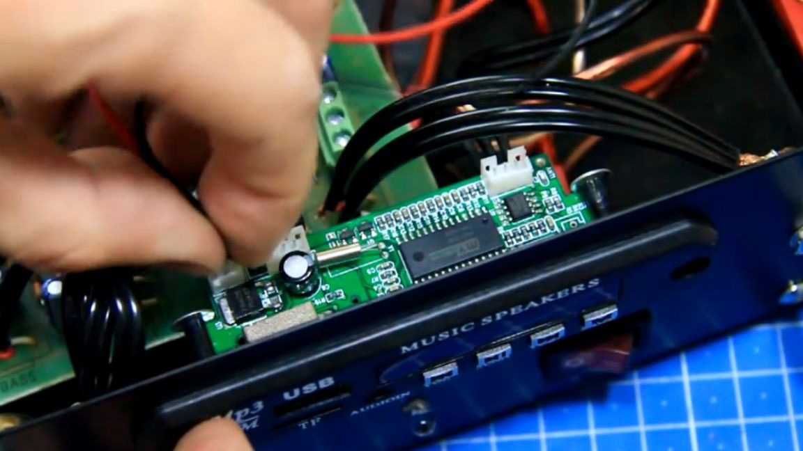
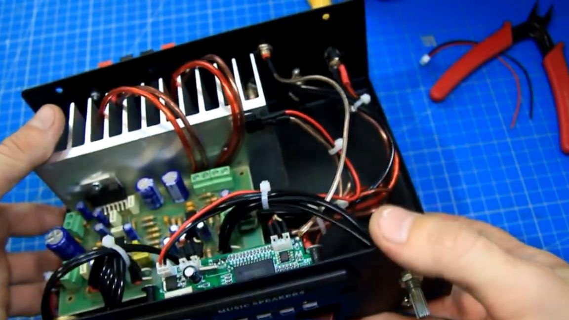
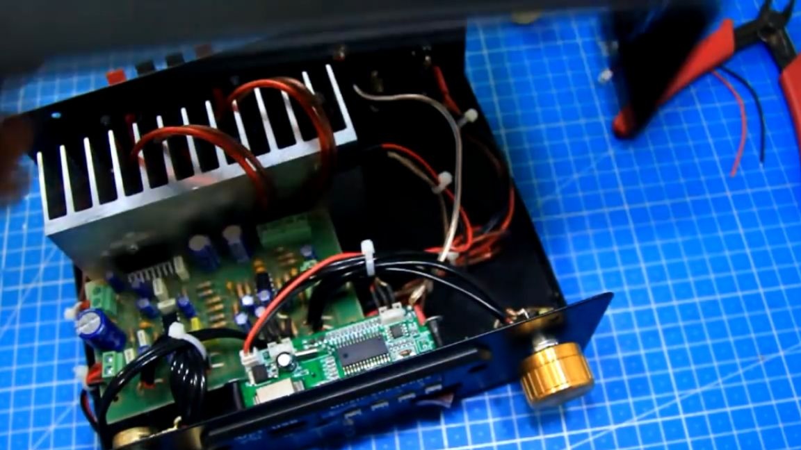
So, now let's get down to assembling the amplifier itself. We will remove all unnecessary. We will use the sound module like this:
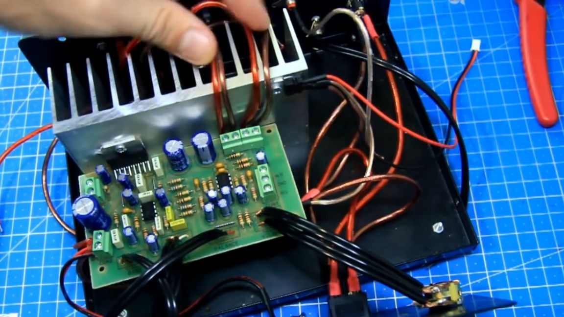
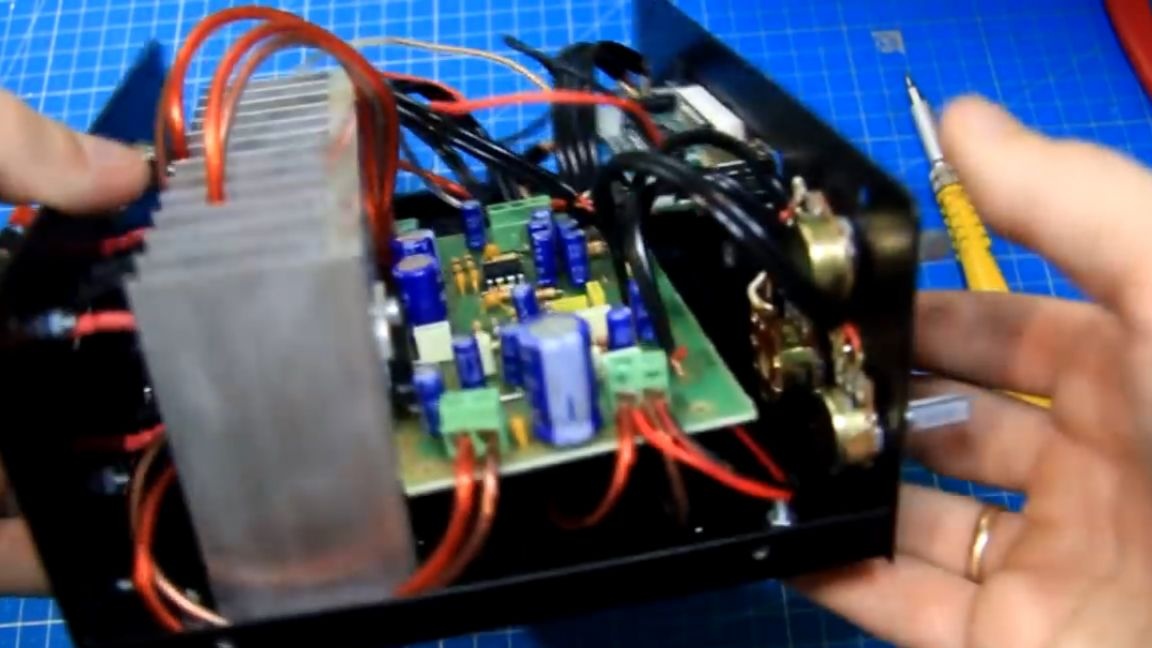
We will also install such an amplifier board in the case:
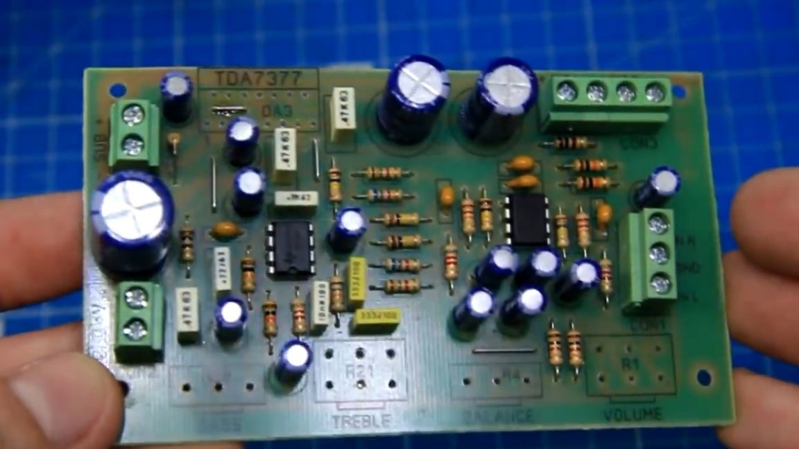
This board simply lay with the author in a box, and now she has found application, especially since there are all the necessary adjustments on it.
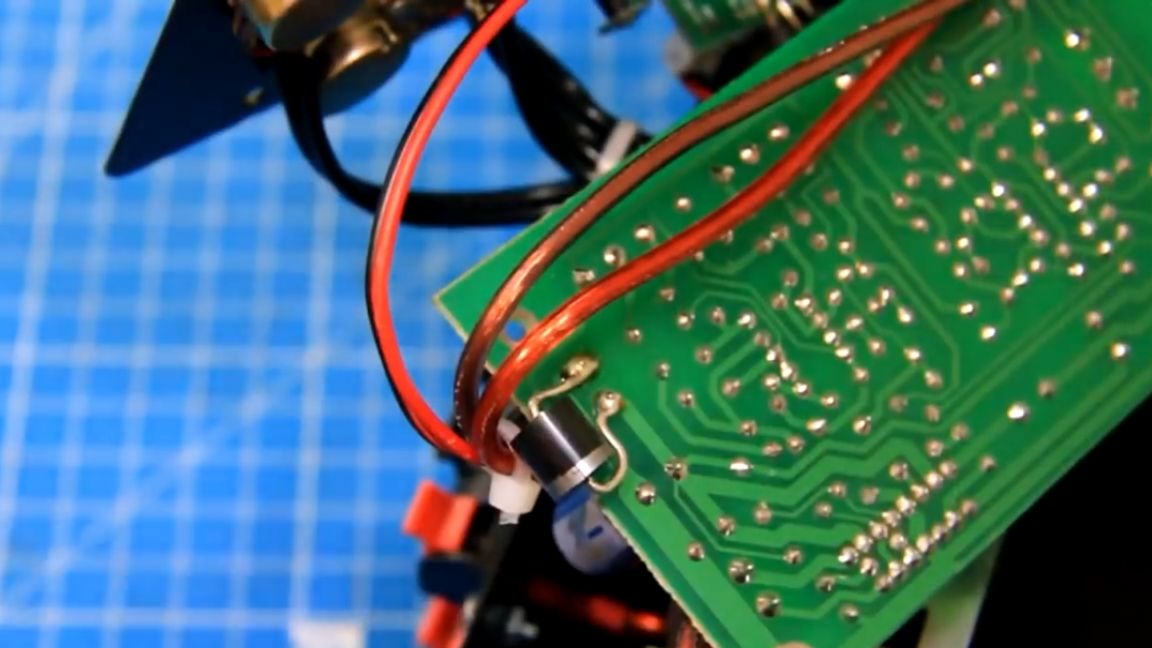
But we will replace the TDA 7377 chip with a similar TDA7379. The TDA 7379 chip has a higher voltage (up to 20V), just under the future power supply.
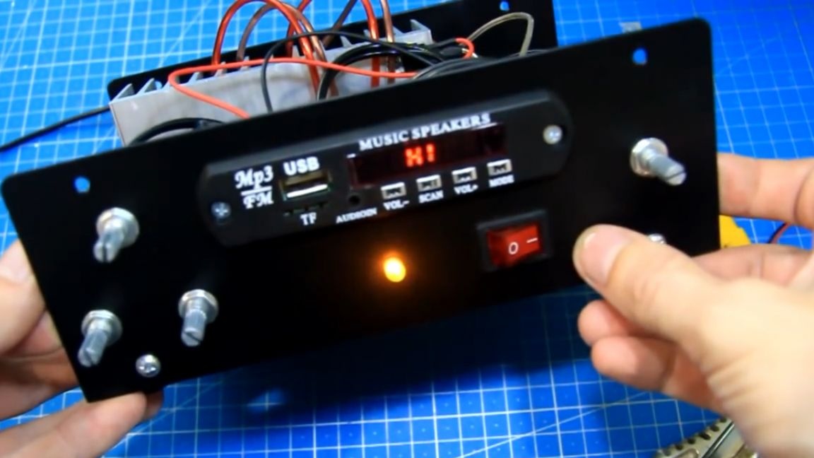
On the front panel, we will have a power button, a power indicator, on the right will adjust the overall volume, on the left will be the volume of the subwoofer, as well as adjust the tone and balance on the satellites. On the back wall of the case there will be a power connector, a linear input, a connector for an external antenna and spring-loaded connectors for connecting satellites and a subwoofer. On the lower part of the case 4 rubber legs are already installed, as well as a radiator.
First, the author, using a soldering iron, unsolders the old sound not working (turned out to be defective) module and removes it from the case.
After this, it is also necessary to get rid of all unnecessary wires, both sound and power.
Now you can say everything is ready to install new modules. First, try on the sound amplifier board. There is enough space for her and this is good.
Variable resistors for all adjustments we put on the front panel. To do this, use microphone shielded wires so that there is no extraneous noise. We solder the braid of the wire on the minus track.
Variable resistors are now taken out, everything is done on the amplifier board, mounted in the case. We leave the power supply wires, from the power connector the plus and minus goes to the switch, and from the switch to the amplifier and in parallel to the 12 V step-down voltage regulator, to power the sound module. To connect the subwoofer, we will install another spring-loaded connector with 4 contacts to close all the holes in the case made earlier. The middle contacts will serve to connect the subwoofer, and the author decided to just glue the two extreme contacts so that they would not be pulled in vain.
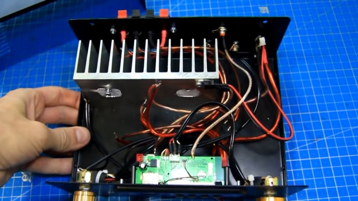
We install the amplifier board in its place. Using thermal grease, we fasten the microcircuit to the radiator.
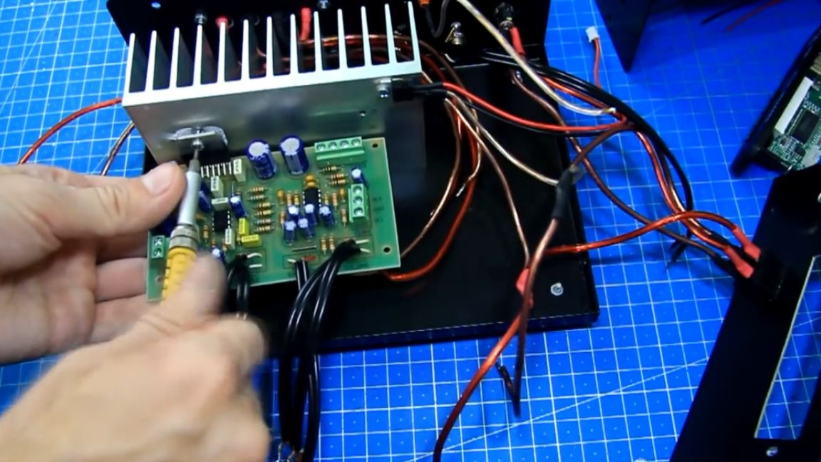
Even on a single chip, the entire board holds normally, of course, if necessary, you can fix it additionally.
Next, install variable resistors and fix them with nuts. And so that they do not rotate in their places, we use glue or double-sided tape. All variable resistors for adjustments are set in place. We can say that the amplifier board is already fully installed. On the front panel, we will make a hole with a diameter of 5 mm for the LED indicator of the inclusion of the amplifier.
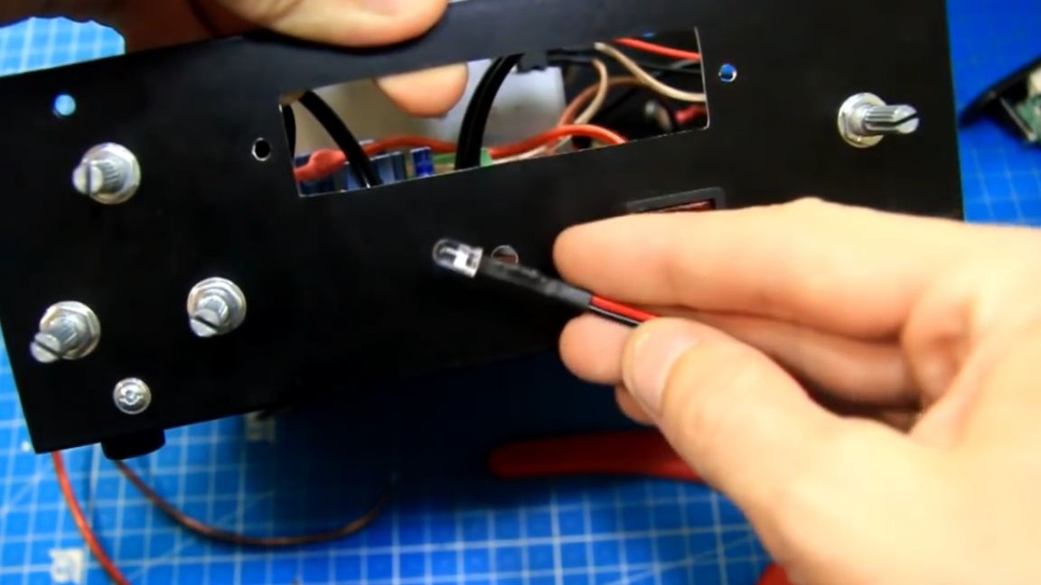
A 2.4 kOhm resistor is soldered into the gap of the plus power of the LED so that the LED does not burn out from a 20V power supply. The LED is connected in parallel to the power supply wires of the amplifier, observing the polarity. After that, again observing the polarity, we connect the power wires to the amplifier board. Just in case, we install a protective diode on the board for power.
Then the author decided to connect the satellite wires, but it turned out to be not very convenient, and in the end I had to remove the amplifier board.
Now there is access, observing the polarity we install wires on the satellites in the terminal blocks. It is very important not to short-circuit them on the radiator. And after that, the author screwed the amplifier board into place. The wires turned out to be short, but it's okay, they will go like this, on top of the radiator.
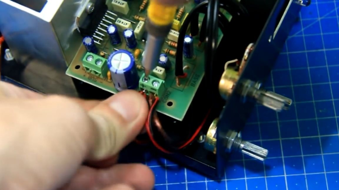
Next, we fasten the wires from the connector to the subwoofer.
We solder the shielded wire to the linear output of the sound module, which we will connect to the amplifier input. And on the line input of the sound module, we will also connect a shielded wire from two tulip connectors on the back wall.
So, solder the wires to the module and install it in its place.
The author noted that the power connectors are different, or rather their polarity, so he decided to check the polarity and it turned out that there could be a pole on the new sound module if power was applied. We change the power on the connector so that the new sound module does not burn out. Now everything is correct, you can connect it to power the sound module.
Then we connect the line-in wire from the sound module to the amplifier input. Be sure to observe the right and left channels.
Next, in our place, solder the antenna wire from the connector on the back wall. The main work on the assembly has been done, outwardly it looks like this:
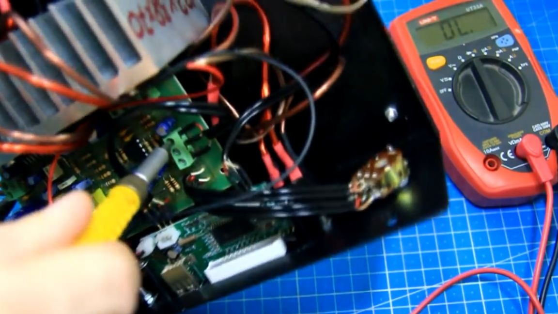
The wires have not yet been laid or fixed. And now you need to power up the amplifier and check the availability of power on the individual modules. We are trying to connect the power supply from the laptop to the amplifier. Once again, check everything and turn on the amplifier.
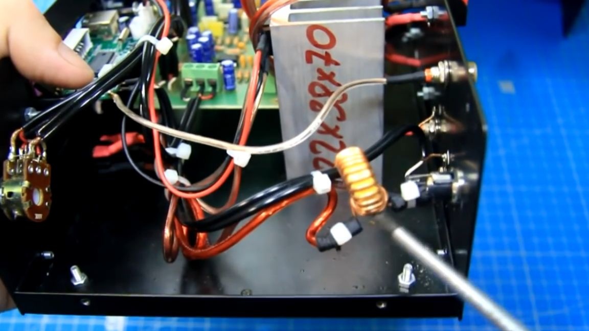
The sound module is working. There is also an indication of the presence of power in the form of a glowing LED. We’ll go over an additional multimeter, there is power everywhere.After all the checks, carefully tighten all the wires with cable ties so that they do not hang out.
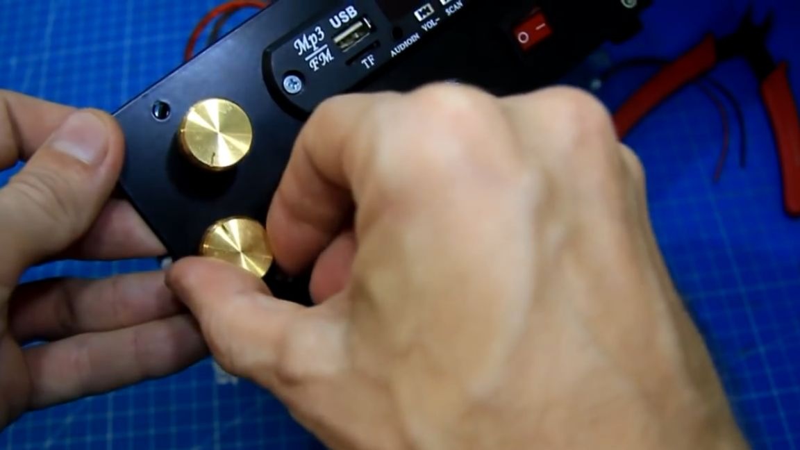
The author did not additionally fix the amplifier board, it keeps well with the wires connected. Such pens were once purchased on the radio market:
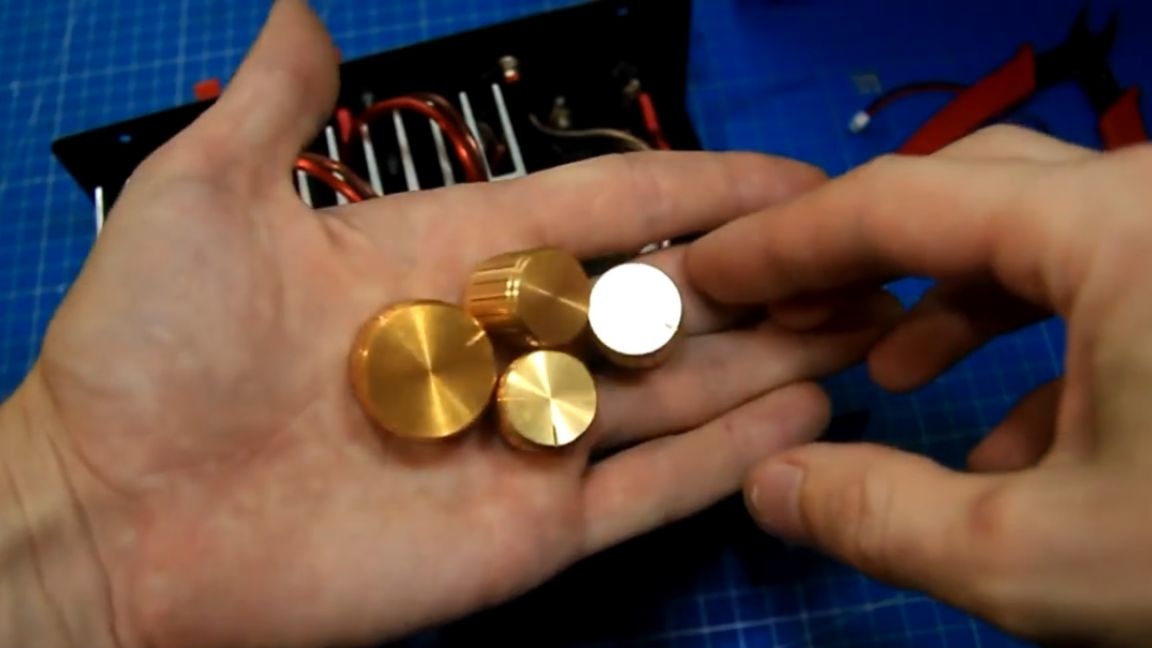
Install them. There will be a larger knob for overall volume, as it is most often rotated and it is more convenient. It turned out that the power supply from the laptop is whistling a little and this is heard in the speakers. To fix this, solder the power supply choke, you can use it from an old computer power supply. The whistle has almost disappeared, but with a more expensive proprietary power supply, there is no whistle at all.
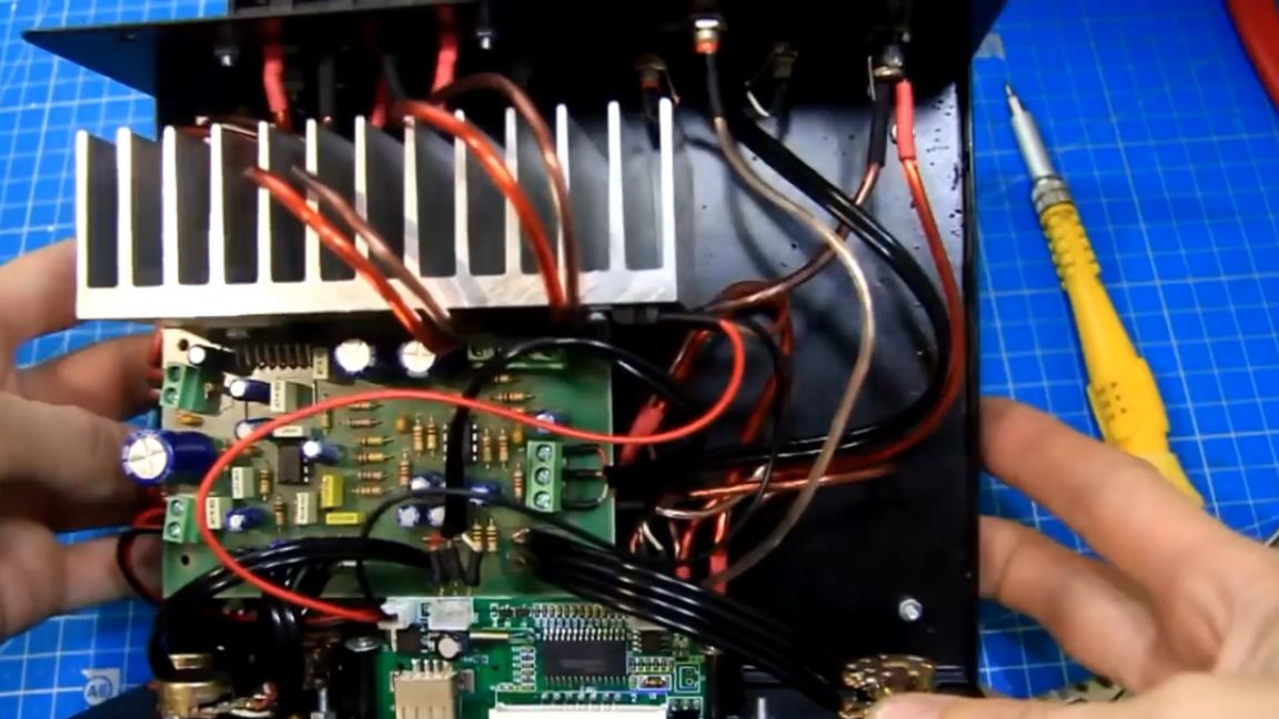
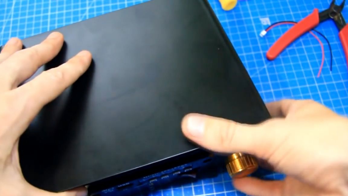
Well, as far as the amplifier assembly is concerned, everything is ready and it turned out like this:
As an amplifier board, you can take another similar module and connect it in the same way or do everything differently, this is already at will and is essentially limited only to fantasy.
Close and lock the lid.
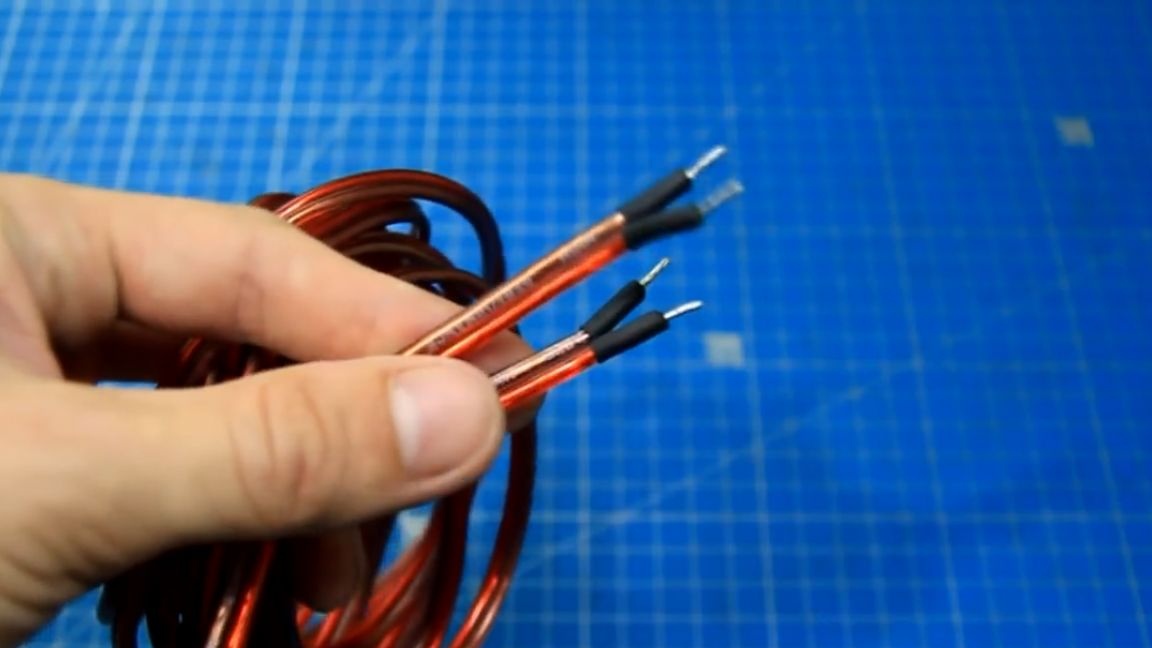
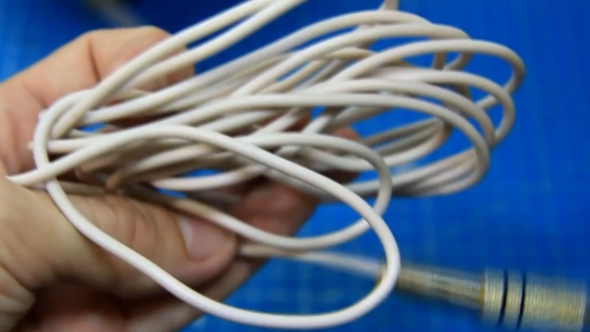
Now the amplifier is finished. Outwardly, he is not big, but weighty. Wires for connecting satellites and a subwoofer can be purchased at the radio store, cross section 0.75 square. For ease of connection, you can solder the ends.
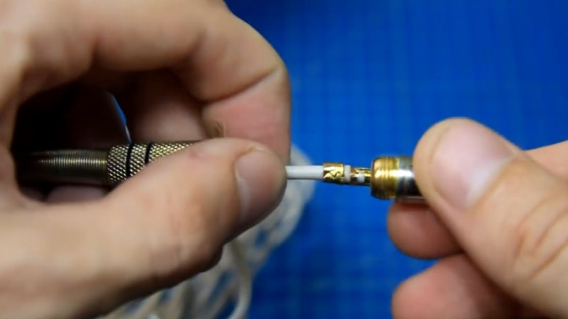
For a more confident reception of the radio, you can make such a budget antenna from a tulip connector and an ordinary stranded wire.
It remains to check the entire product assembly and whether it plays at all. We connect the power supply, subwoofer and satellites. We check everything and turn on the amplifier.
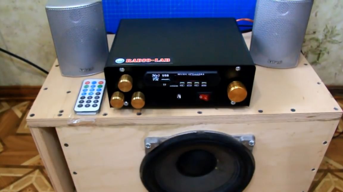
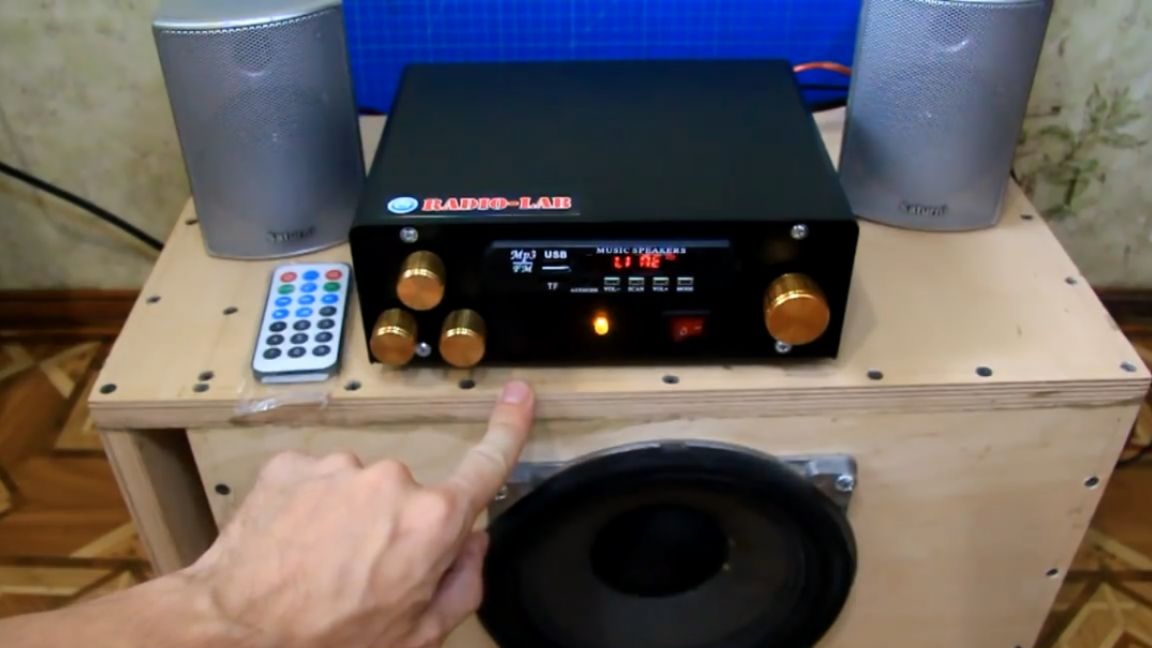
There is no popping, there is a little squeak, but it is barely audible. The amplifier works, the music plays, this is very good, then everything is done correctly. The radio catches fine. Now you can connect a USB flash drive and check all the adjustments.
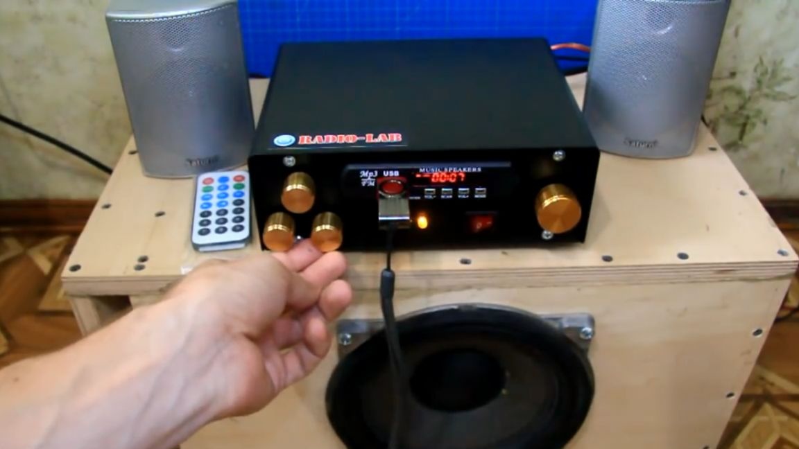
Well, here we have such a 2.1 system. It turned out very budget, by the way, and it can be powered from the battery. The system is playing very well. It is possible to customize to taste.
Thank you for attention. See you soon!
Video: