
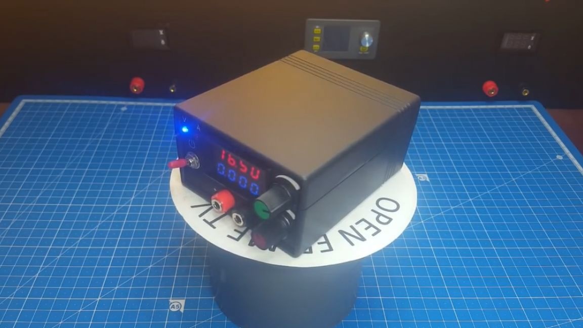
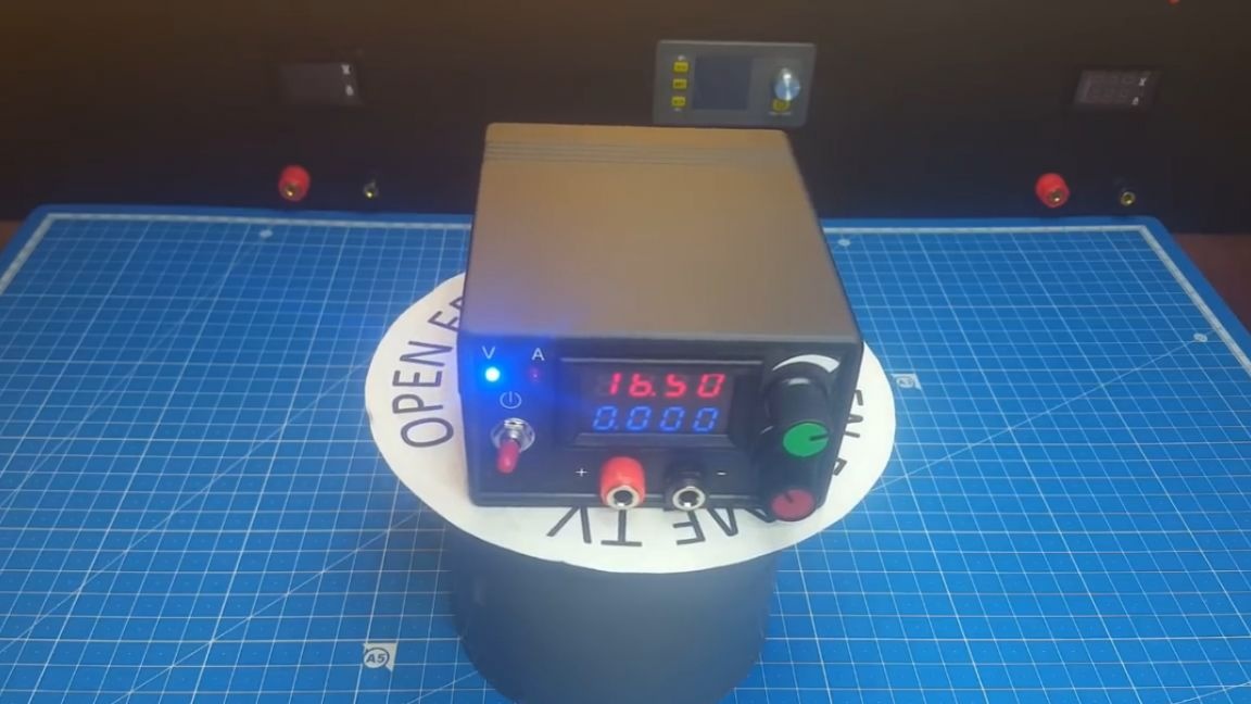
The topic of collecting devices on Chinese modules is now popular on YouTube. Roman (the author of the YouTube channel Open Frime TV) also decided to keep up with the trends and put together such an autonomous battery pack:
So let's get started. First, let's go over the characteristics:
- output voltage from 1.2V to 26V;
- the output current can reach 1A;
- battery life with a maximum load of 40-50 minutes, if the load is reduced, then, as the author assures, calmly enough for a couple of hours of work;
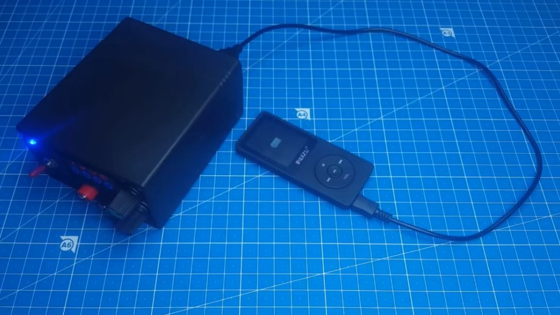
- Also, this power supply has USB charging, so it can be used as a bank.
A bit of background. The author came up with the idea of collecting such a block after a week-long power outage. It was connected with the weather. At that time, Roman was repairing the power supply and spent a lot of time waiting for the voltage to come on. Now, having a makeshift battery pack handy, such interruptions will not scare any amateur radio operator. The master will be able to work in any conditions.
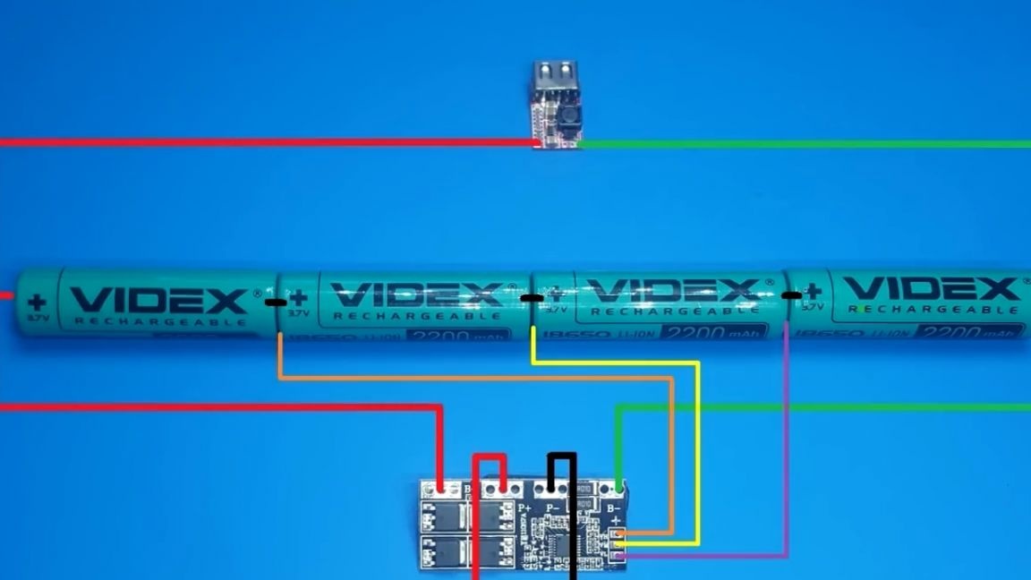
Now let's see what this power supply consists of. First of all, these are batteries. The larger the capacity, the better. In this case, the author used 4 lithium-ion batteries with a capacity of 2200 mAh each.
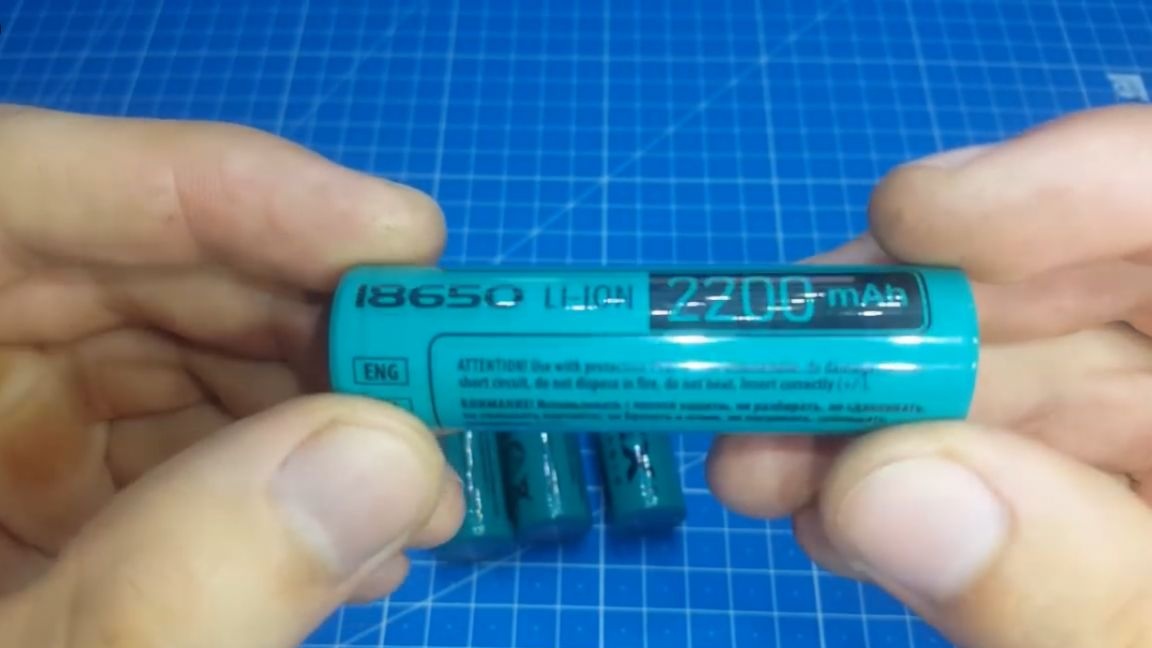
There was also a dilemma on how to connect batteries: in parallel or in series.
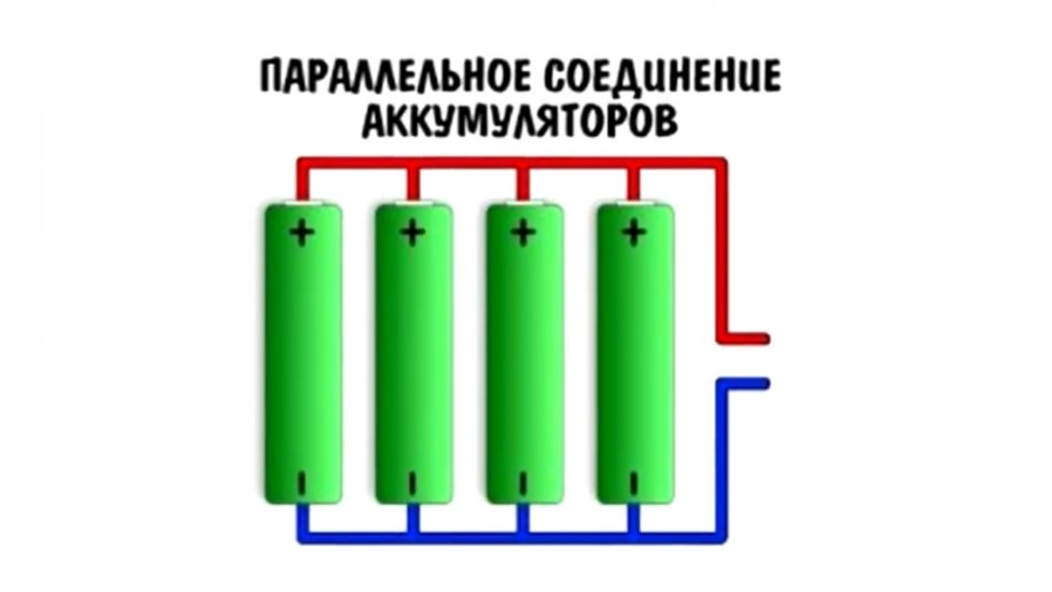
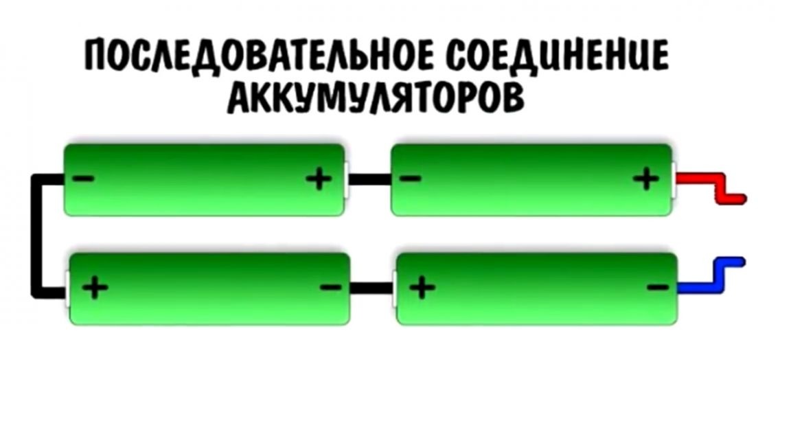
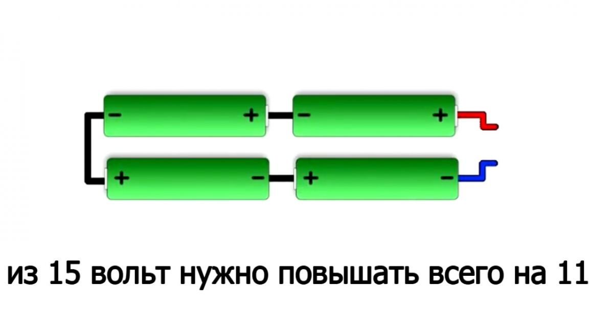
The second option won, since the energy accumulated in the batteries does not depend on the connection, but the efficiency in case of a serial connection is higher, since it is easier to increase the voltage from 15 volts than from 4 ex. I think you caught the author’s train of thought.

The second problem that the author encountered is how to charge the batteries. First thought: this is to take the balancer on the tl431 chip (as the author of many already familiar YouTube channels Aka Kasyan did), but since we collect everything on ready-made modules, such a balancer was specially purchased for this project for 4 cans of lithium-ion batteries.
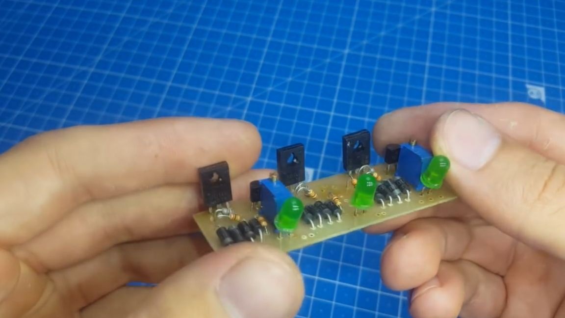
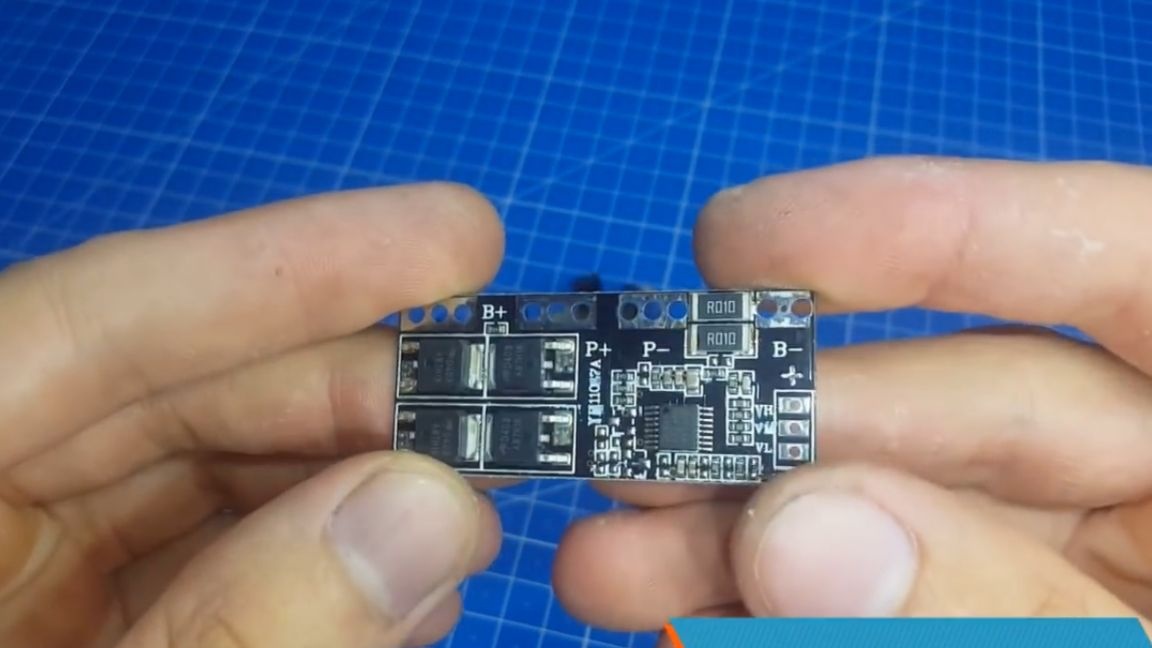
If anyone does not want to spend money on such a balancer, then in the archive, the author attached a diagram and a signet for self-assembly in the archive (see the SOURCE link at the end of the article, the archive is in the description under the author’s original video).
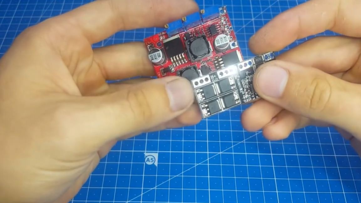
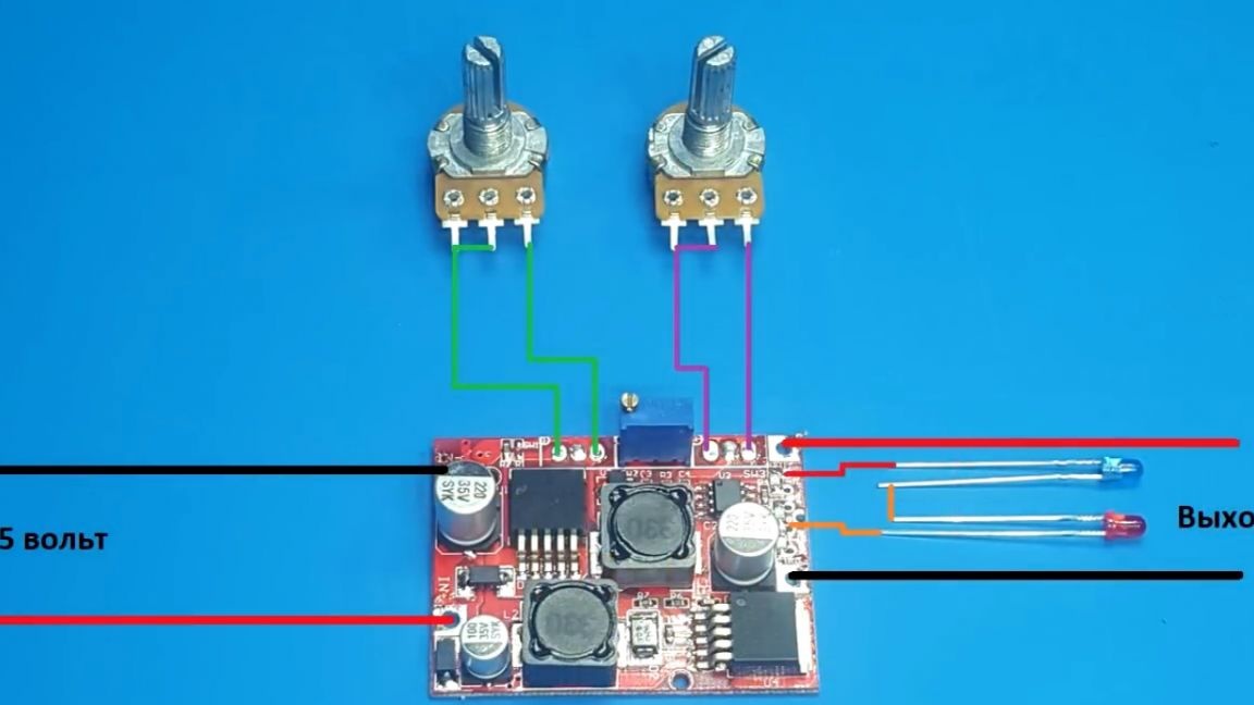
Well, now move on to the brain circuit. This is such an up and down dc-dc converter on the lm2577 and lm2596 chips.
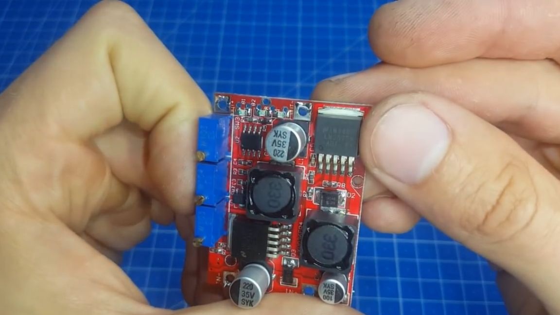
Its feature is that it monitors the input and output voltage and, depending on this, turns the boosting chip on or off, thereby increasing the efficiency. The module itself is small and fits perfectly even in miniature cases. There are 3 multi-turn resistors on the board. Of these, we need only two.
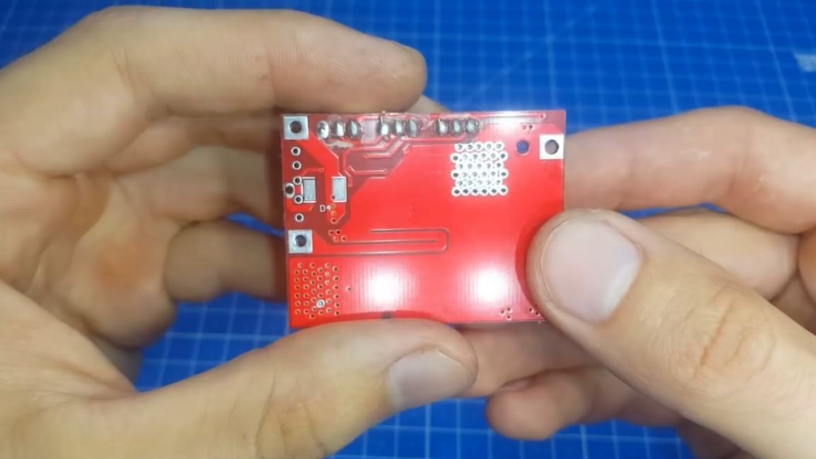
One to adjust the voltage, and the second to adjust the current. They will have to be removed from the board and the usual resistors that will be installed on the case will be soldered in their place. As you can see, the factory boards look very nice. And those that radio amateurs do as they say "on the knee" do not look very good.
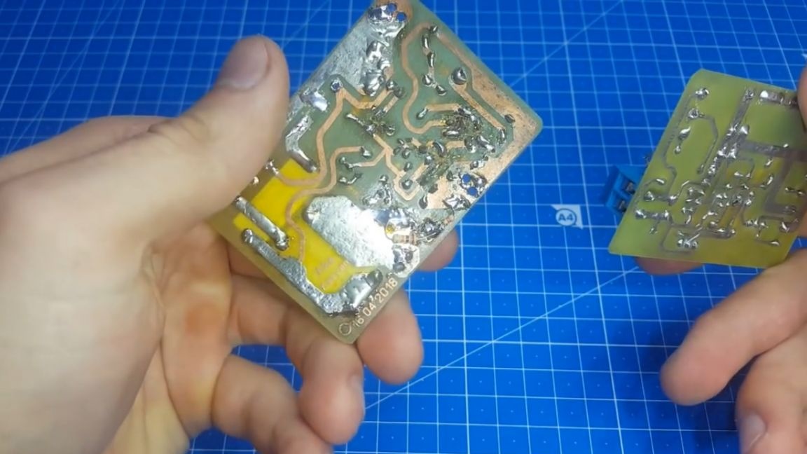
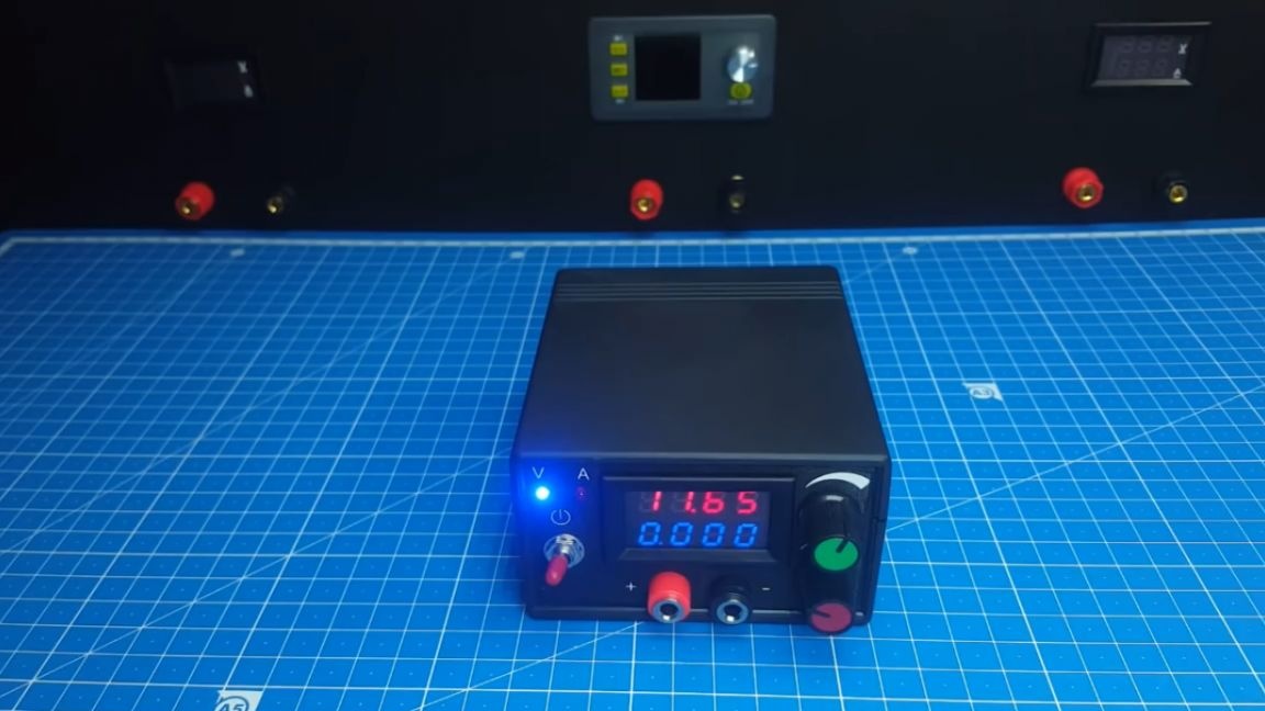
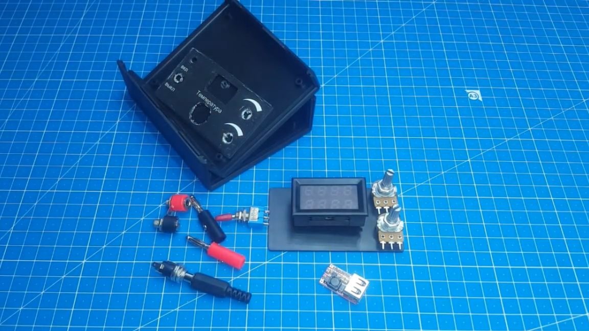
Therefore, the author recommends not making printed circuit boards by ourselves, but ordering ready-made ones. Such boards turn out to be of high quality and pleasing to the eye, they just feel like soldering. When we figured out the boards, we will take up the manufacture of the case. The author had such a small box in which he recently assembled a soldering station:

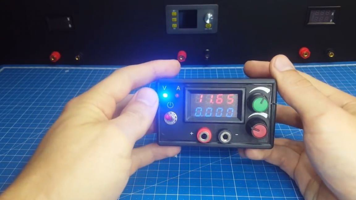
For this reason, one sidewall is already with holes, but there is nothing to worry about, you still need to make the front panel. It is necessary to bring a switch, resistors, and also a multimeter to the case. The author will use this one with four characters:
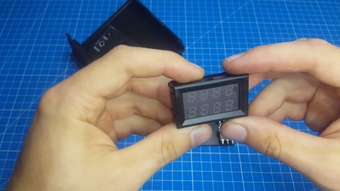
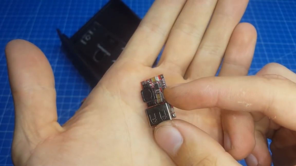
To connect to the power supply, install the terminals. On the back there will be a charging slot and a USB connector. As a power supply for usb, we use here such a mini dc-dc voltage converter, which has a usb socket on the case, which is very convenient. Plus, it is not adjustable, and this also makes it easy to connect.
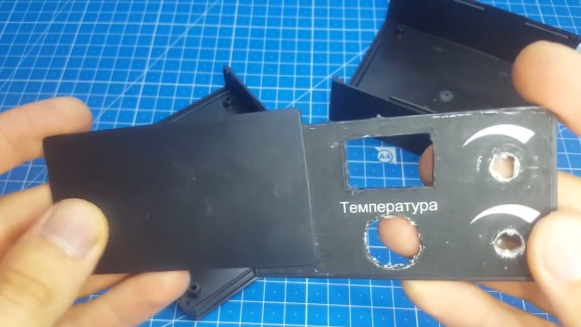
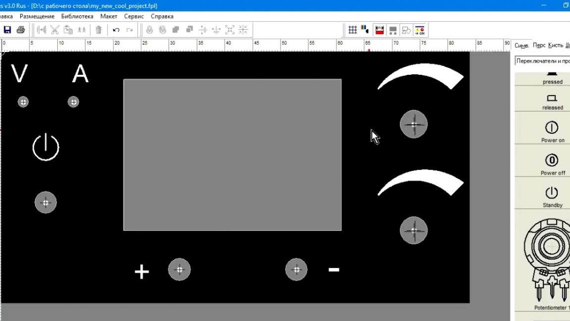
Getting to the manufacture of the body. To do this, in the FrontDes computer program, we will make the front panel. We print it on the printer and use double-sided tape to attach it to the sidewall.
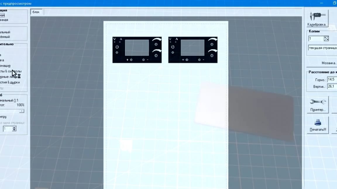
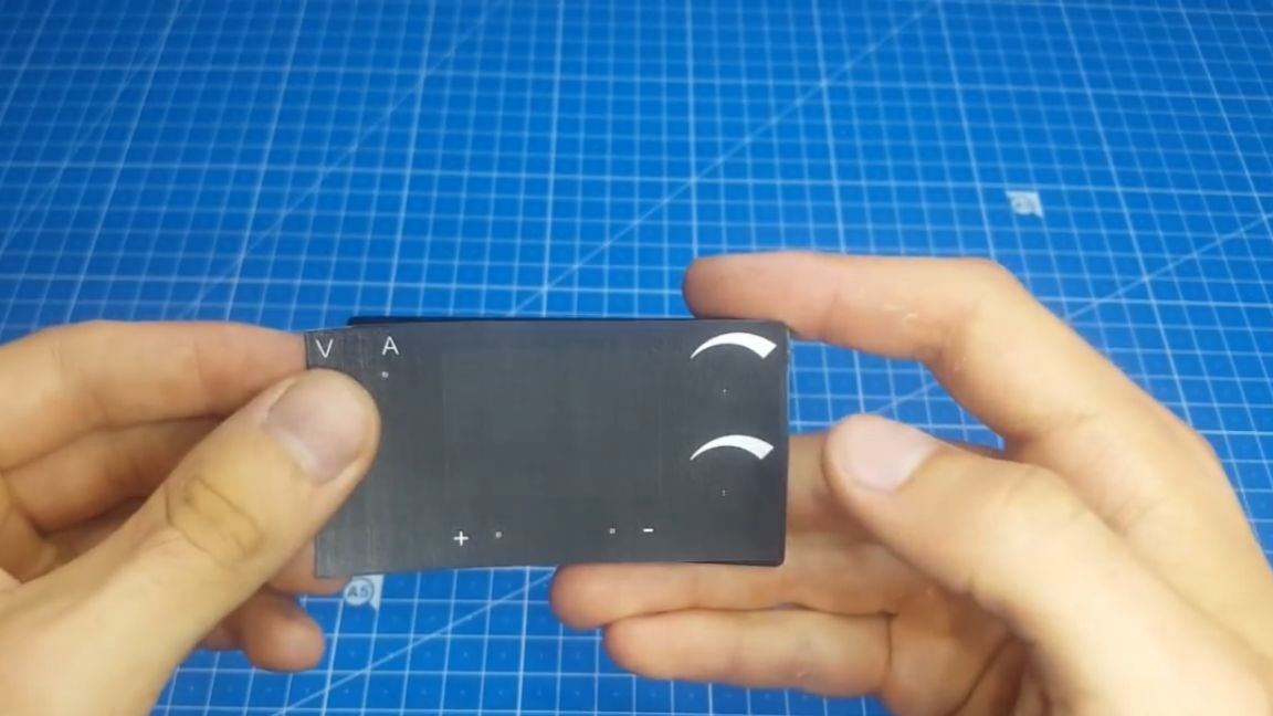
Now you need to make holes for the components. The result is such a beautiful socket:
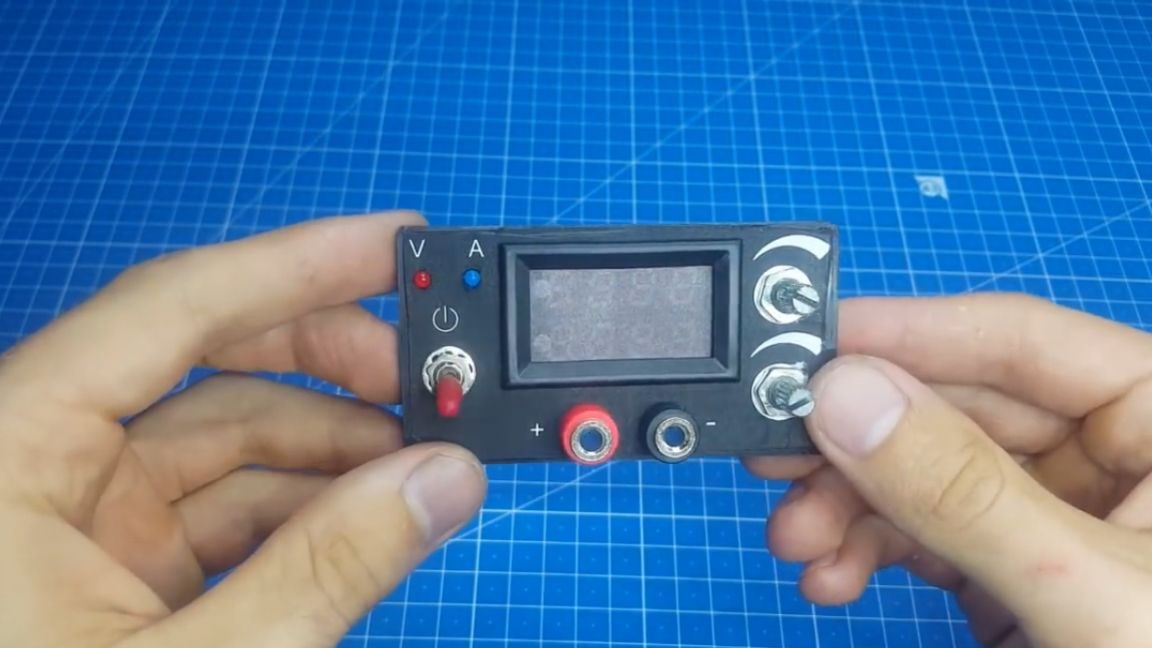
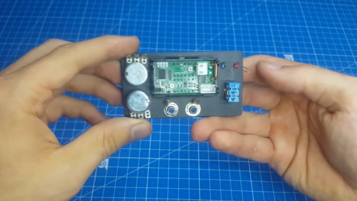
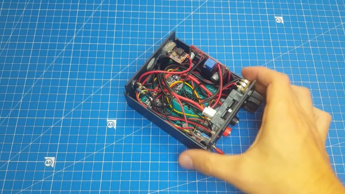
We fix peripheral devices on it and begin to assemble the power supply unit. Even a child can handle it. You can see all the connection schemes on your screens.
The author painted simply and easily. For convenience, he added these pictures to the project archive (the SOURCE link at the end of the article). We finish soldering and fixing all the necessary components. As you can see again, it was not without hot glue. This is not surprising, but the device is not afraid of shaking and can be safely transported.
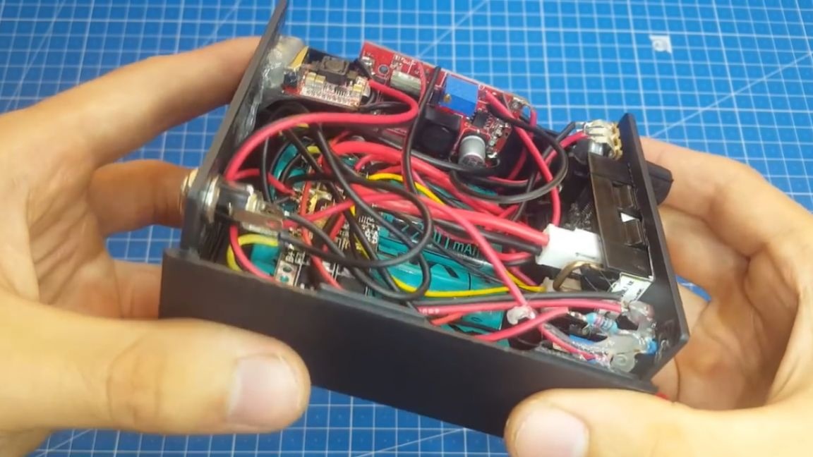
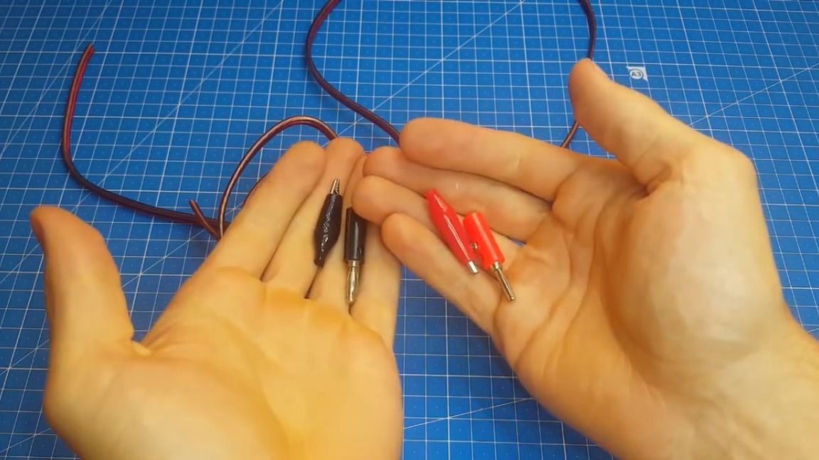
We close the lid and now we need to prepare the connecting wires for connecting the load. Everything is extremely simple here. We connect “bananas” to one side of the wire, and at the other end we plant 2 “crocodile” type clamps.
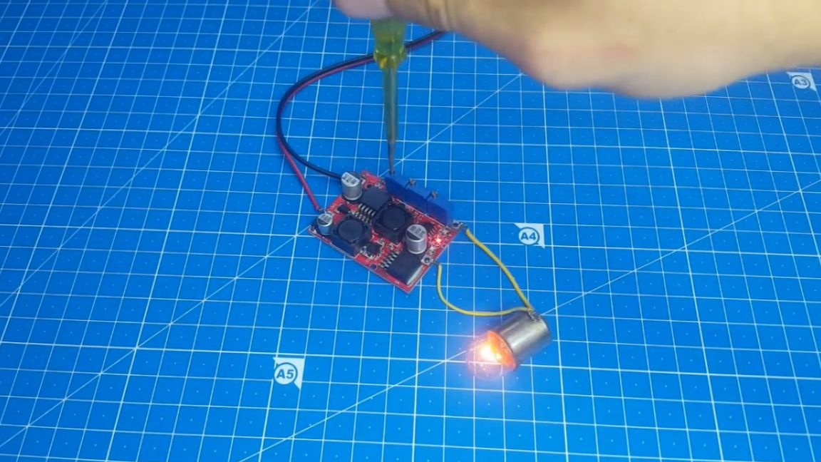
Now you can start the tests. To get started, connect a 12V bulb with a power of 5W.
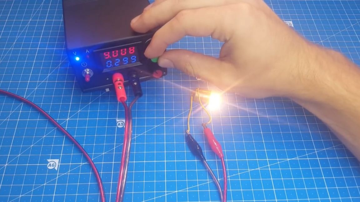
Our home-made power supply without any problems produces the electric current necessary for this lamp. You may notice that both voltage regulation and current regulation work. Now make a short circuit.
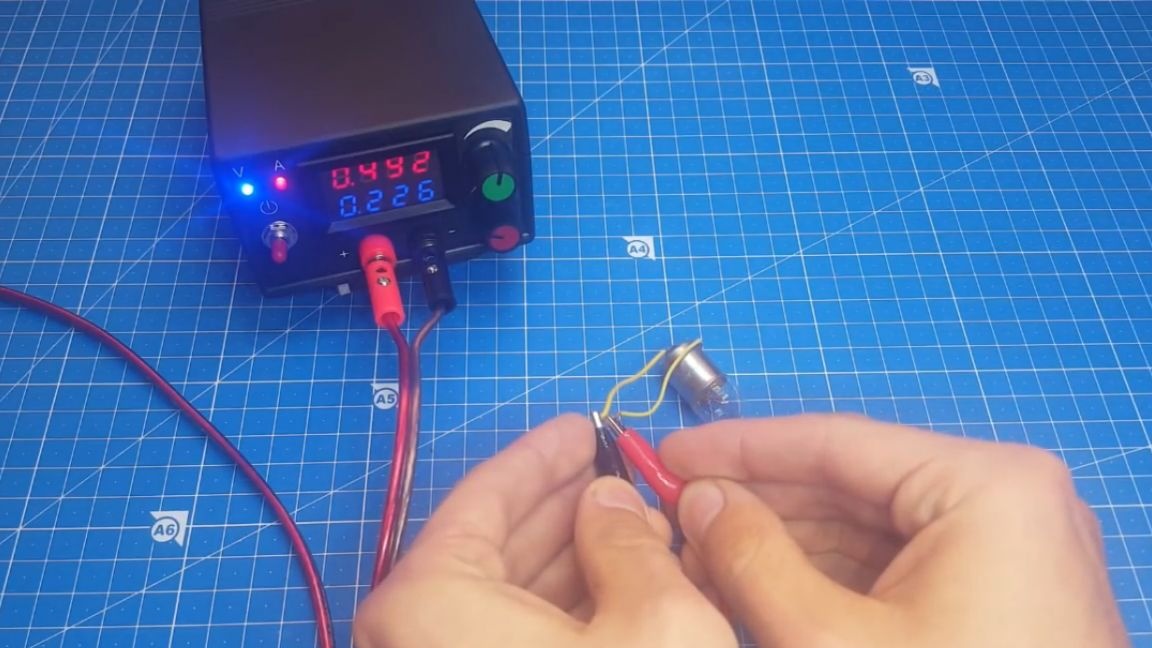

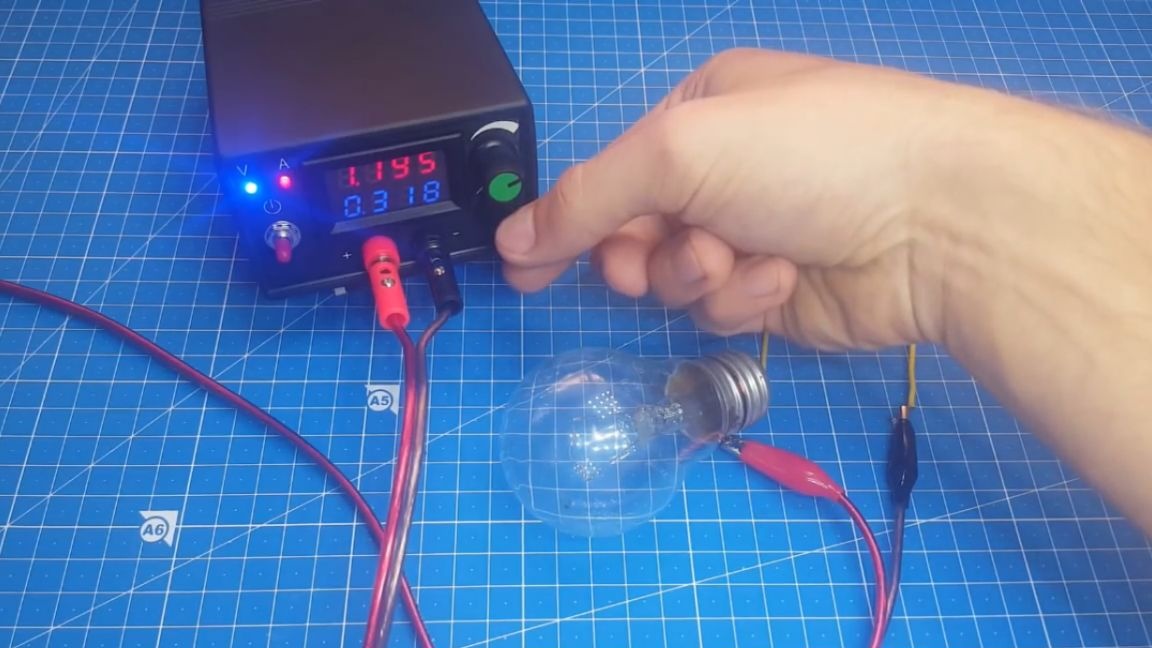
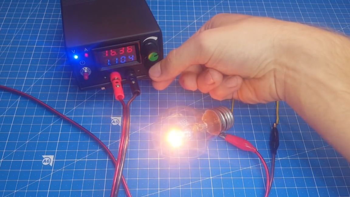
In this mode, there is simply a limitation of the previously set current. Well, the last test. Now let's connect a more powerful load and see if our homemade unit can cope with such a task. The load will be a lamp rated for 36V 60W. We give a current of 1A. At the same time, a small whistle is heard, but we get the necessary current.
Summing up, we can say that the collected do it yourself the stand-alone battery pack keeps its parameters declared at the beginning of the article and this is quite enough for minor repairs.
As a result, we have a great device that you can brag to your friends with ham radio. Well, that’s all. Thank you for attention. See you soon!
Video: