
In this article, we, together with the author of YouTube channel Radio-Lab, will assemble a transistor audio amplifier with a power of 150W.
The author has long intended to try to assemble a sufficiently powerful transistor from scratch. After some time, one rather interesting circuit and amplifier board was found on the Internet.
The author of this amplifier is Ilya Stelmakh, on the forums he is Nemo. An amplifier circuit is a typical Lin topology circuit. There is short circuit protection at the output.
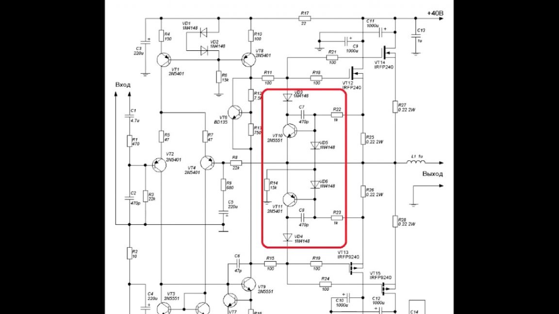
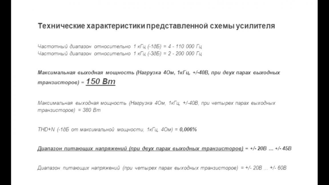
Technical characteristics of the above scheme:
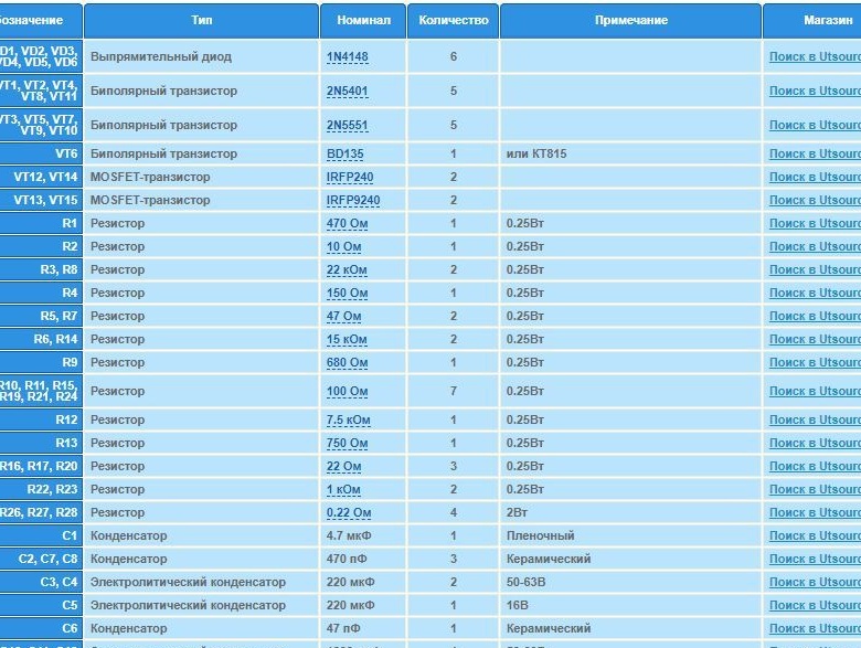
List of required radio elements:
In the description under the video (the SOURCE link at the end of the article) you will find.

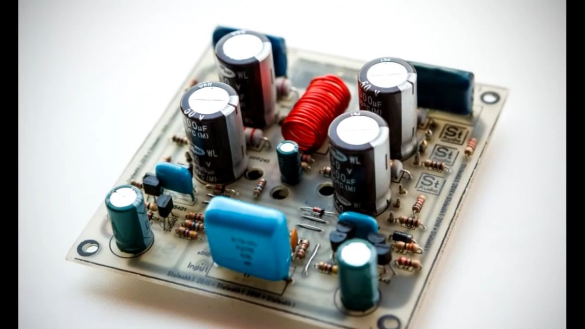
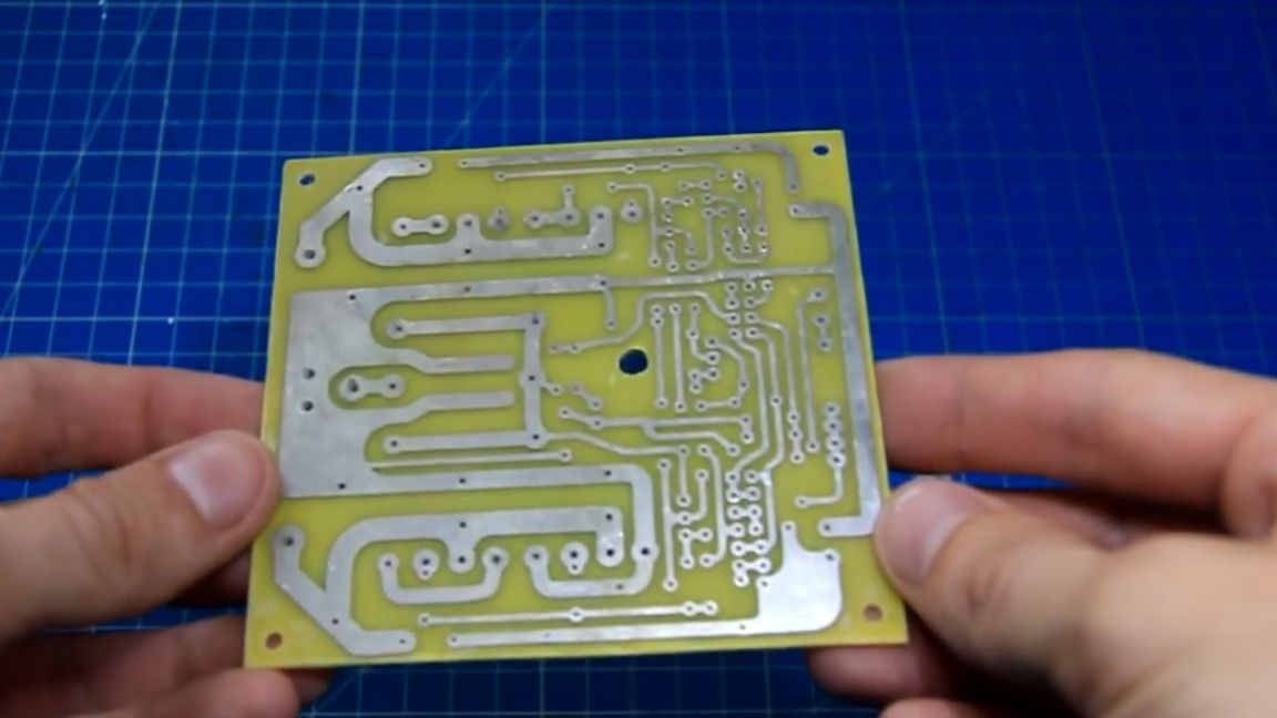
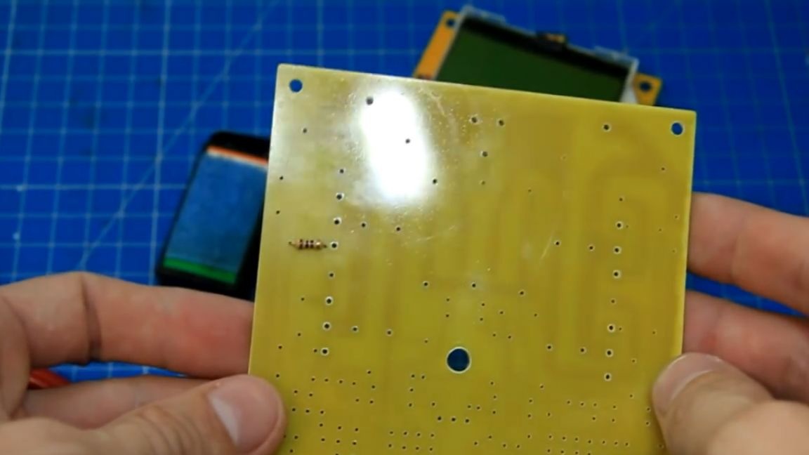
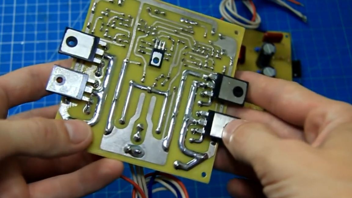
And now it's time to start assembling this amplifier. By the way, another name for this amplifier is “Amplifier without unnecessary show-offs”. As a result, we got such a printed circuit board using negative photoresist.
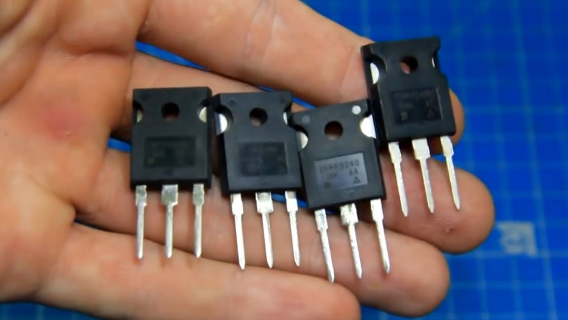
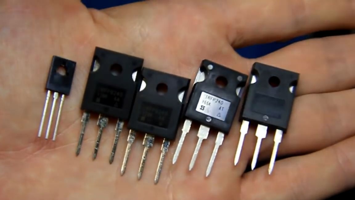
On the radio market, the master bought the necessary radio components for the amplifier. I also bought normal power field-effect transistors, alas, but sometimes there are trimmed fakes.
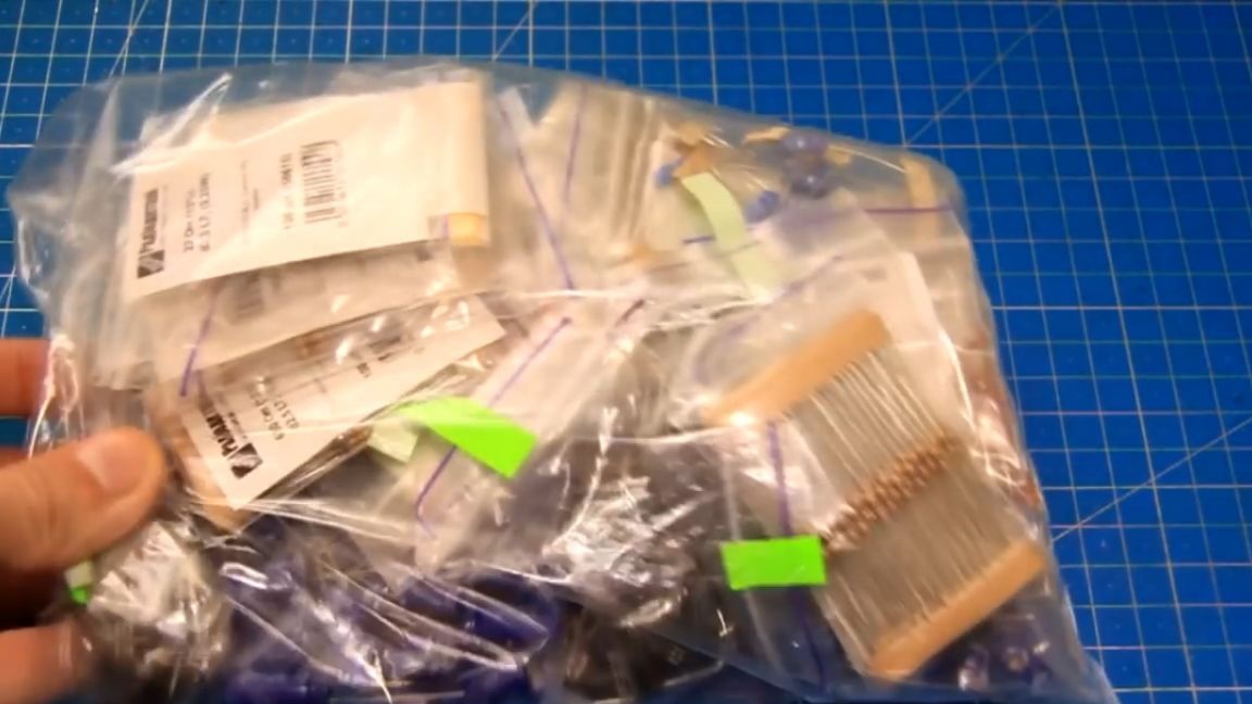
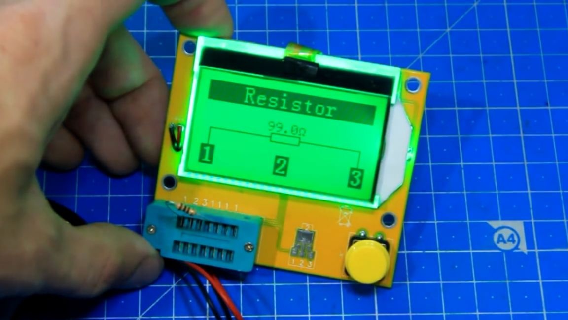
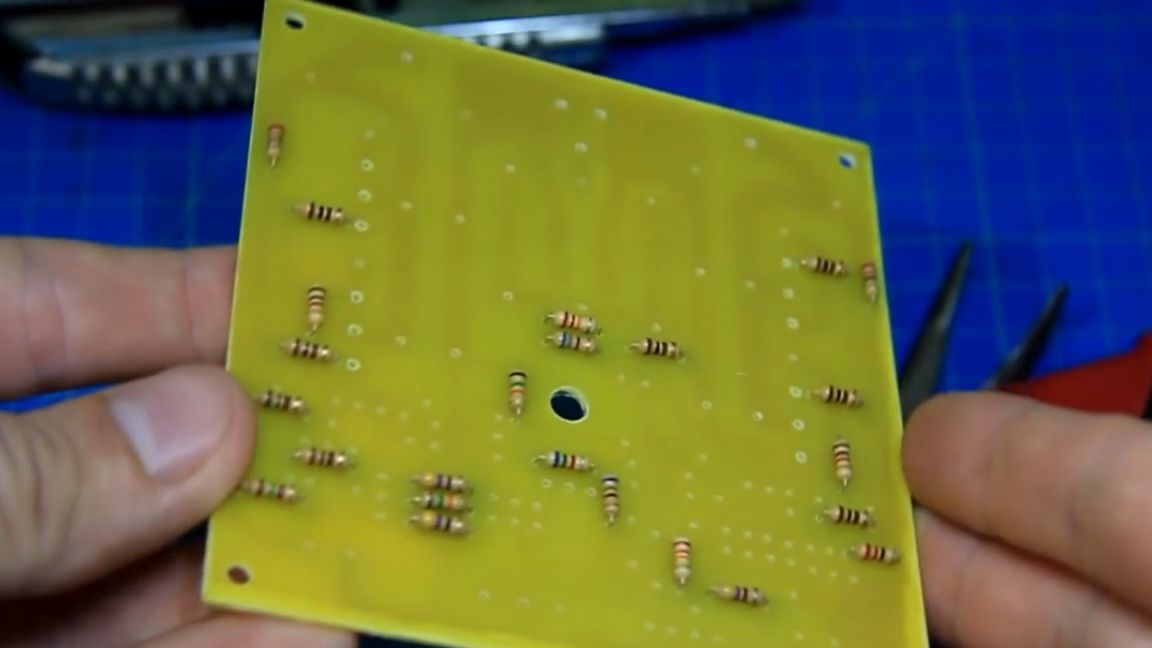
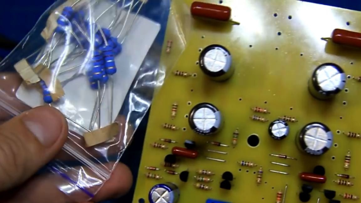
There are many permanent resistors, and in order not to confuse the desired value, the author uses a radio parts tester. Everything is extremely simple here: it is enough to install a resistor, and the tester shows its nominal value. This, you see, is very convenient.
Further on the drawing, we find the installation location of each resistor on the board and install them in their places. Bite off the excess and solder the part. Thus, gradually and without haste, we install all other small resistors on the board.
From the legs of the capacitors we make and solder the jumpers. Then, observing the polarity, solder small diodes. Small transistors have forward and reverse conductivity. According to the scheme, we install them in their places.

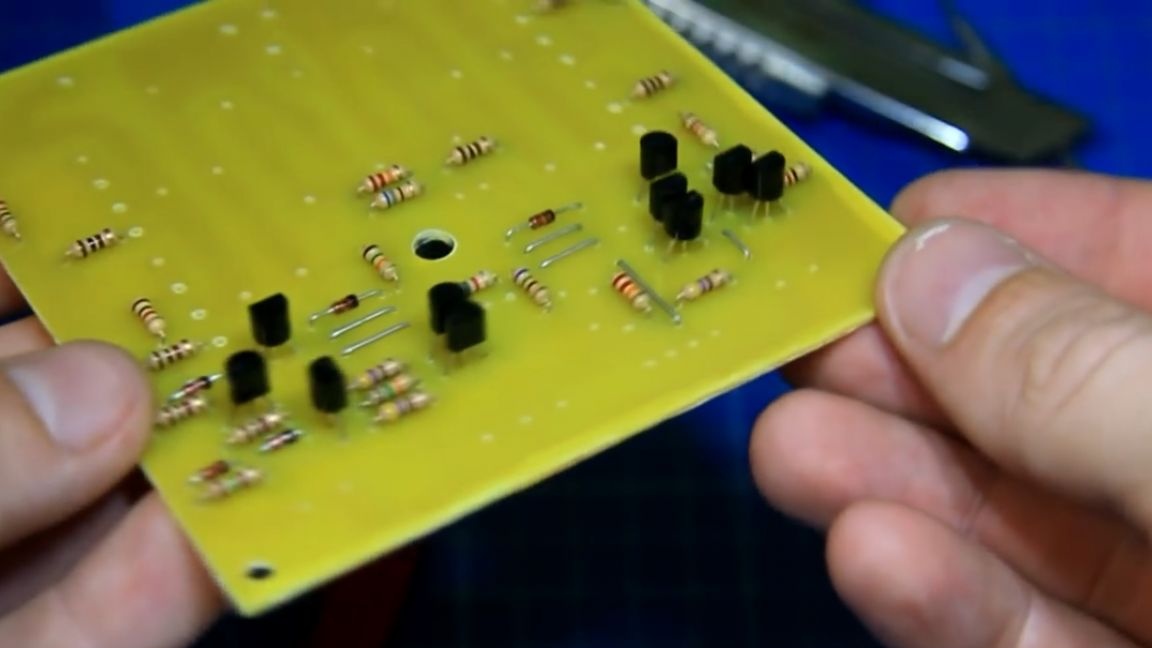
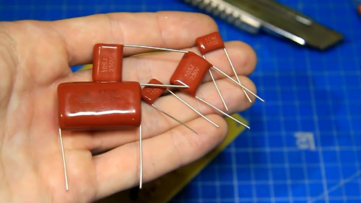
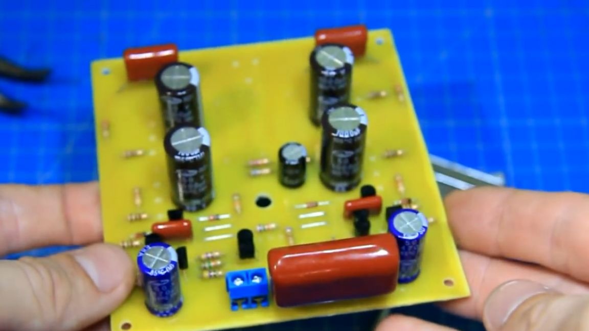
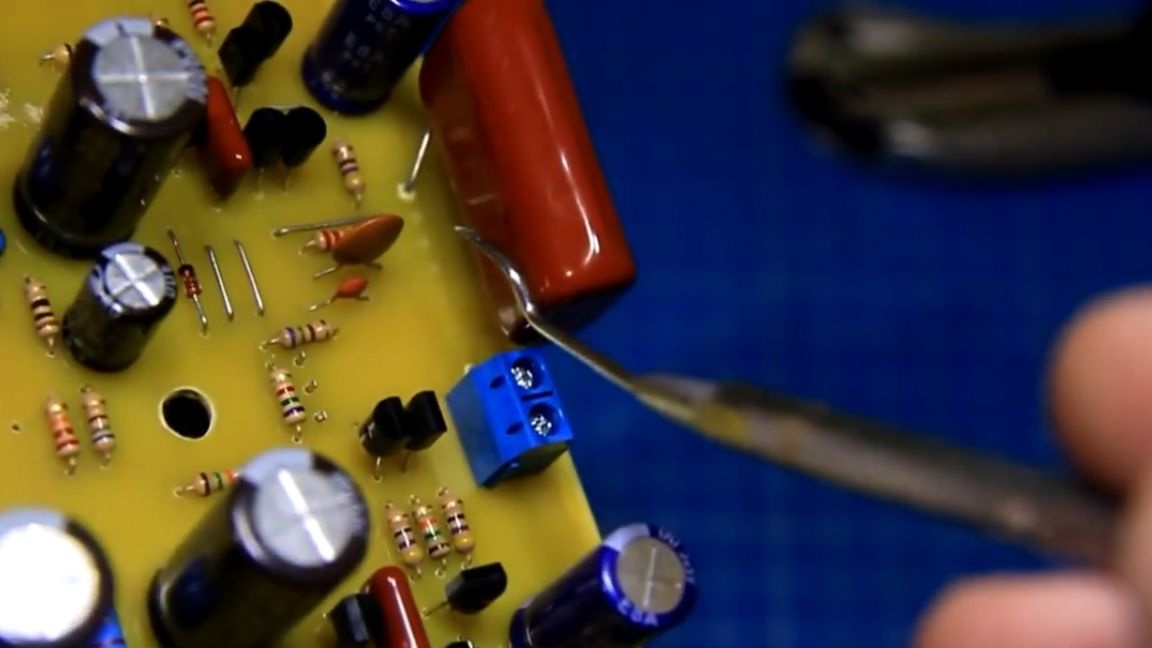
Now you can install film capacitors. There are few of them. And we seal the stasis of the linear input terminal block. At this stage, the board looks like this:
There are also few electrolytic capacitors and, observing the polarity, we solder them on the board. The polarity is indicated on the housing.
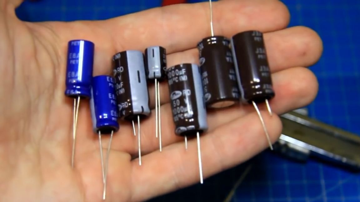
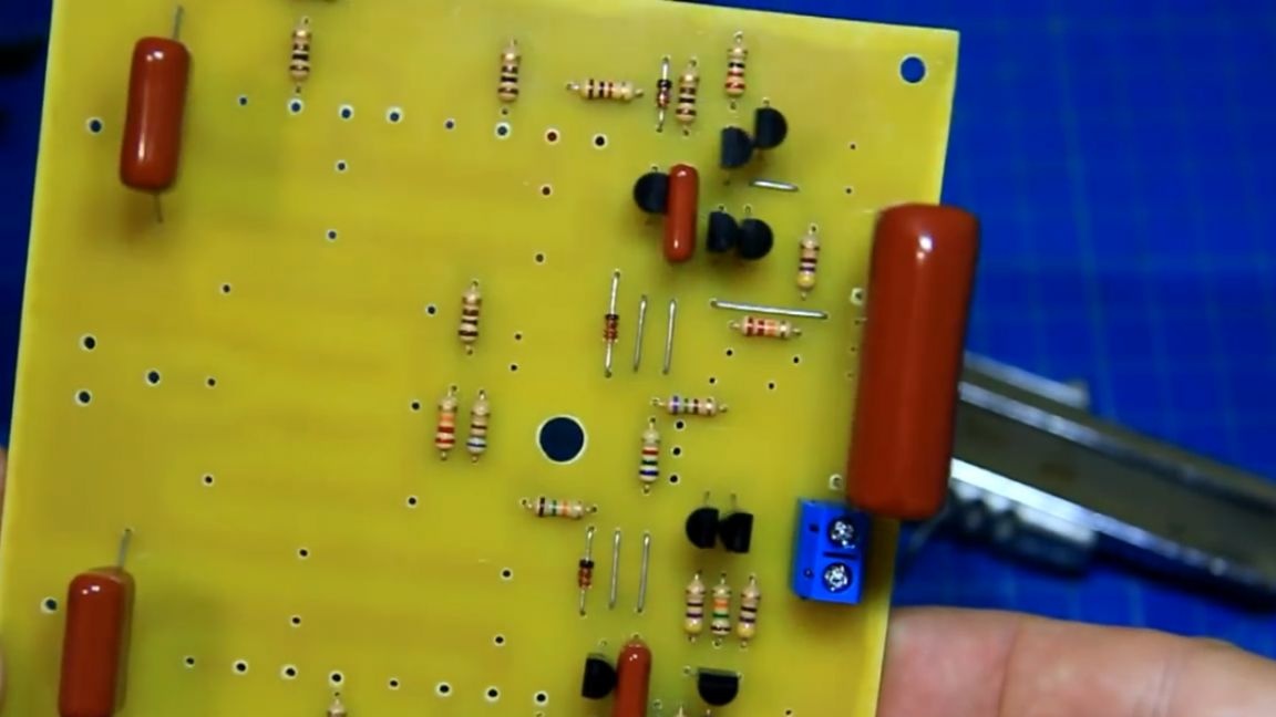
Exactly, we also have powerful emitter constant resistors. They are also sealed in their places.
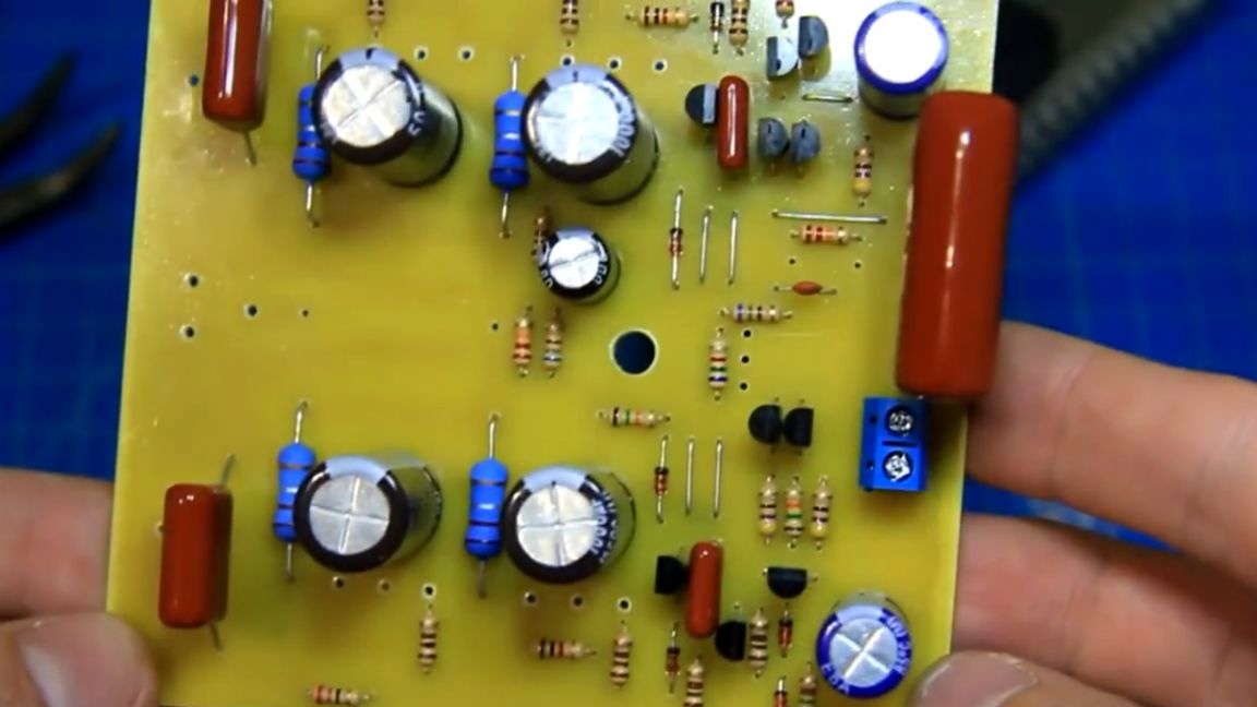
At this stage, the author found a mistake. Instead of the desired resistor at 10 Ohms, he set the resistor to 100 Ohms, you need to check everything. The error must be corrected, now the resistor of the required value has taken its place on the board.Next we will install power transistors. To install power transistors, we bend the legs at a right angle, set the desired height and solder the transistors on the board.
Very important! For his project, the author deployed large power transistors so that they act for a fee. He did this for himself, but on the board, he made changes so that everything was correct according to the scheme. Also on the board there are two small non-polar capacitors, we also install them.
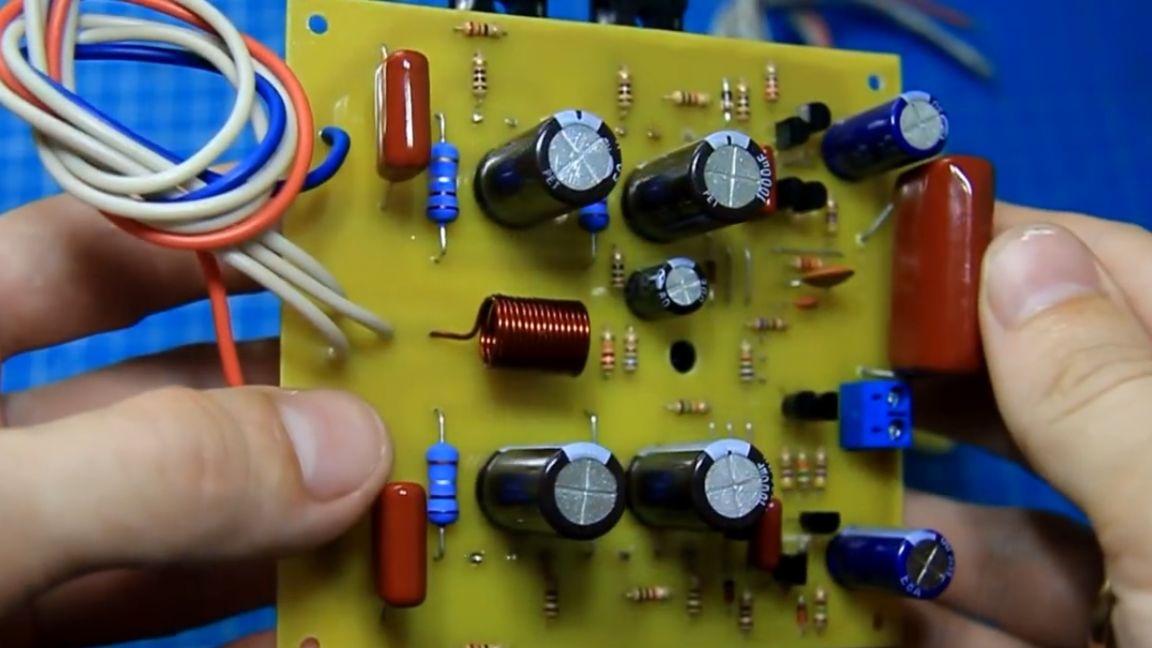
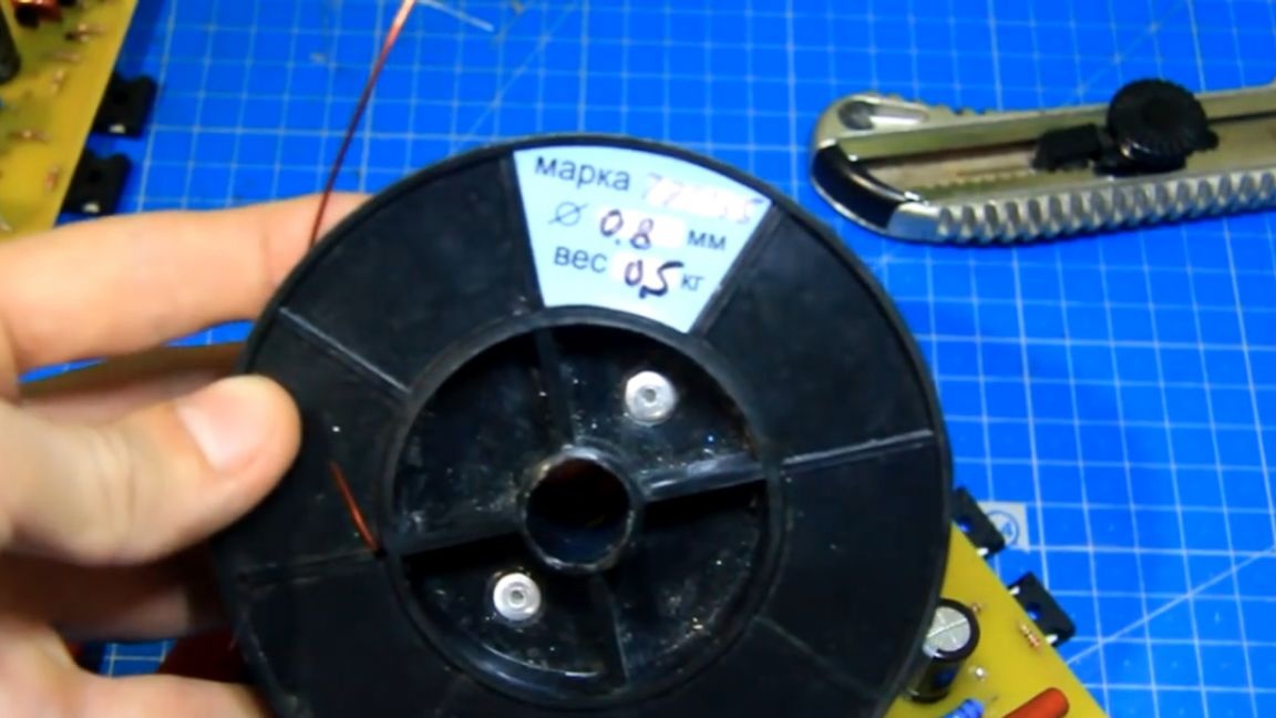
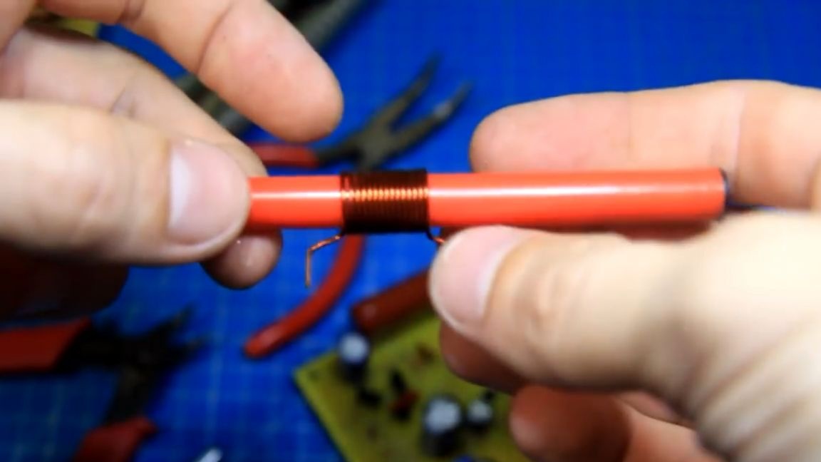
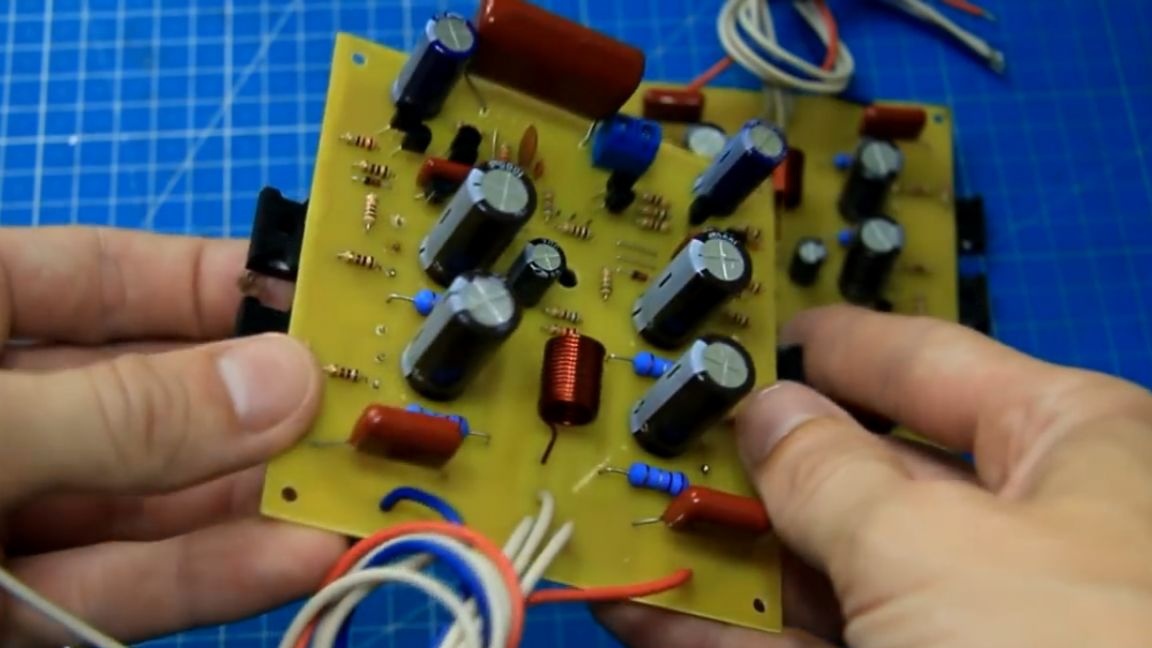
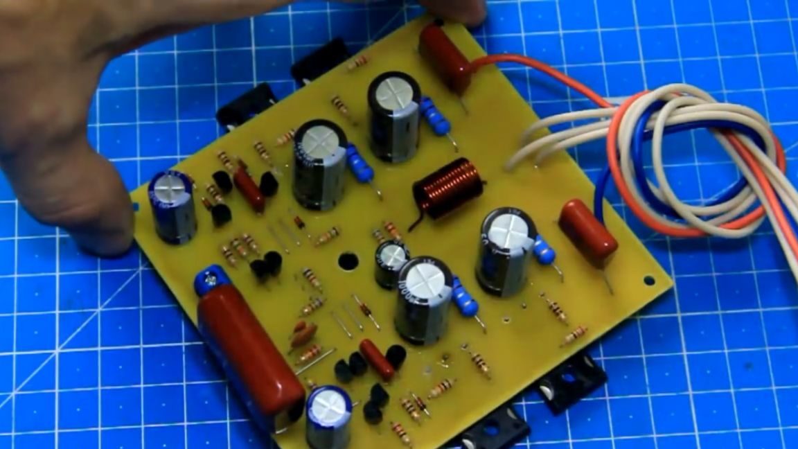
To make a choke, the author bought a copper winding wire. And he wound the throttle on a rim from a felt-tip pen. Then he cleared the soldering spots of enamel, and sealed it in its place.
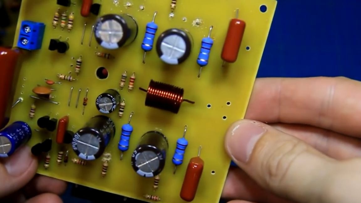
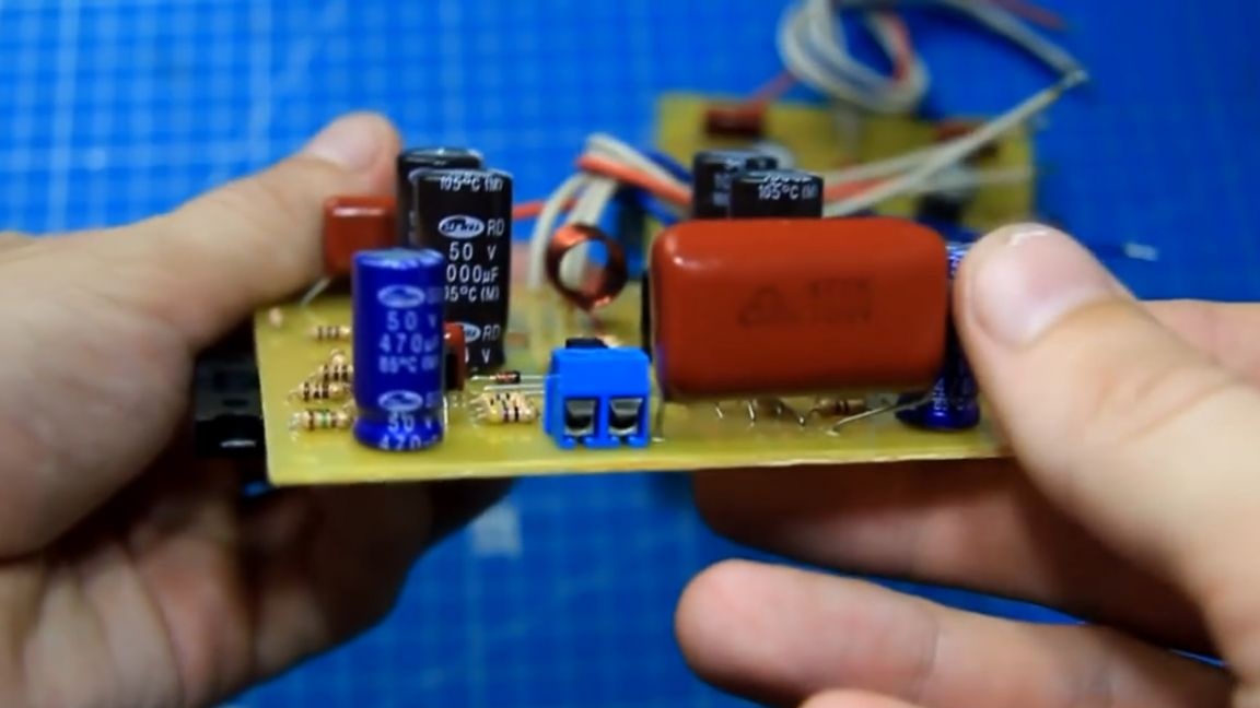
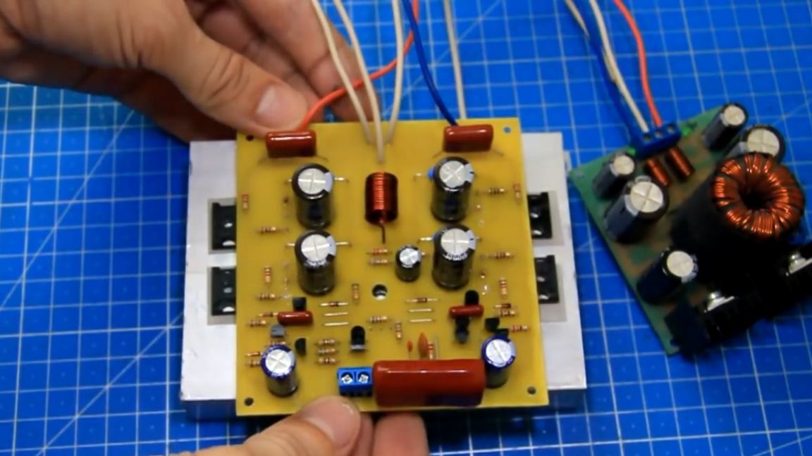
Also, for the convenience of connecting, we solder not very long wires to connect the power of the amplifier and the output wire to the speaker. After the work done, we got such a assembled sound amplifier board:
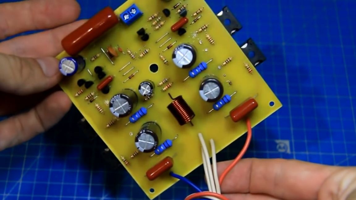
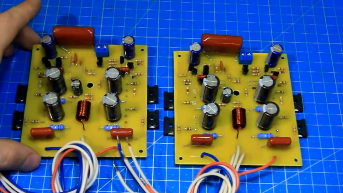
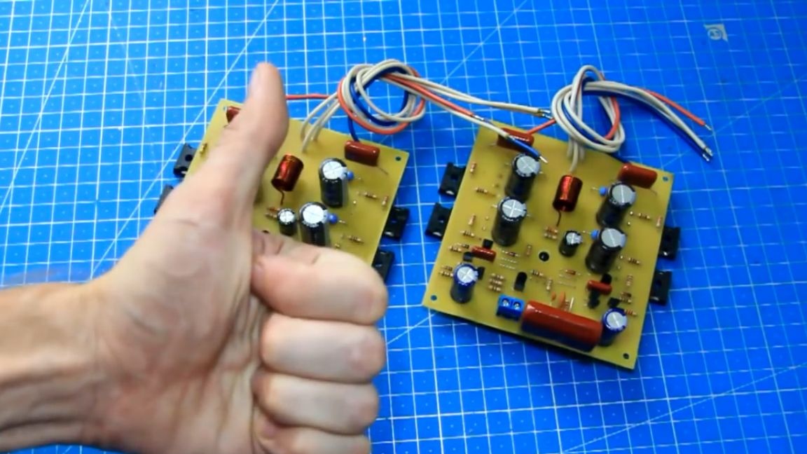
Agree, the appearance is very worthy. Power paths the author additionally shed solder and washed the board from rosin. And as you already managed to see, he assembled two such boards, each on his own channel (if you need to assemble a stereo amplifier).
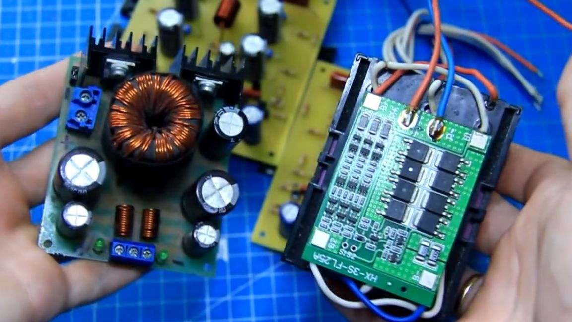
Assembly is certainly good, but the amplifier still needs to be checked for performance. To do this, we will use a 12V battery and a step-up inverter with a bipolar output to power the amplifier.
If by chance there is an error in the assembly of the amplifier, then the inverter does not burn the amplifier and does not burn itself.

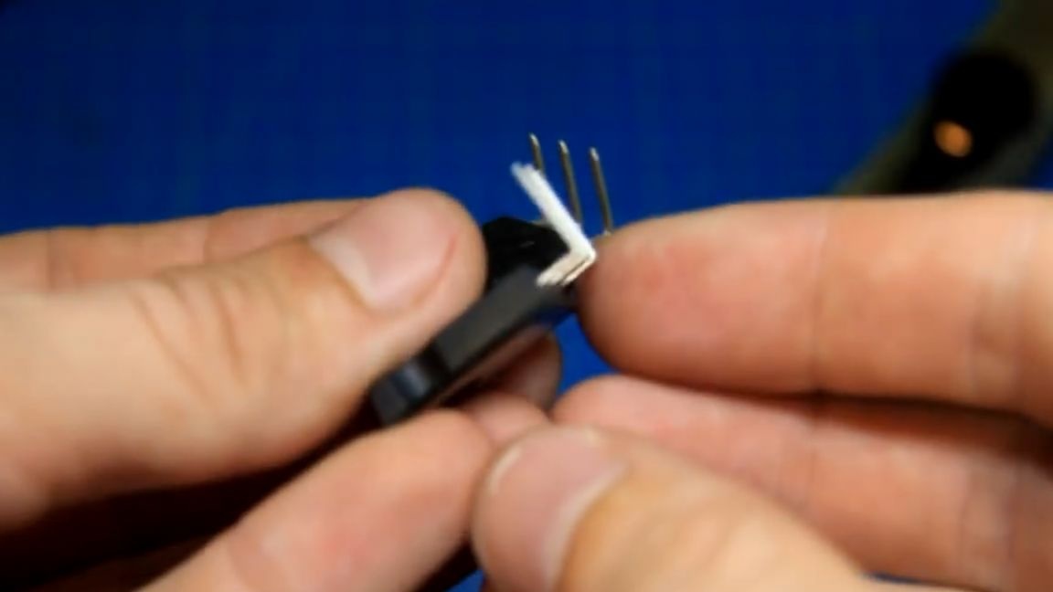
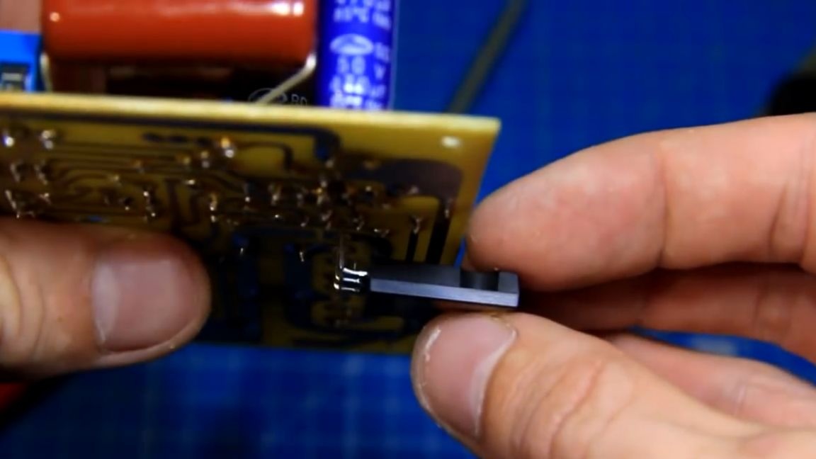
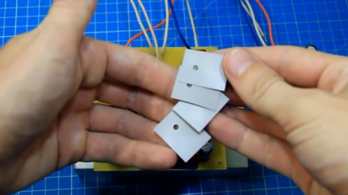
Power transistors heat up quite a lot, they need to be put on a radiator. We have a small test radiator. It is also necessary to isolate the transistor cases from the radiator with the help of insulating gaskets so that they do not short out among themselves.
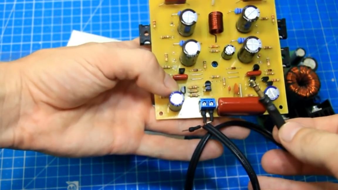
For the test, we do not fasten the amplifier. To the input of the amplifier, the author screwed a shielded wire with a 3.5mm connector. Visually, everything is fine, you can try to apply power. When you turn on the amplifier for the first time, you don’t need to connect the speakers right away, but you need to use a multimeter to check if there is a constant output from the amplifier. This must be done so as not to burn the speakers.
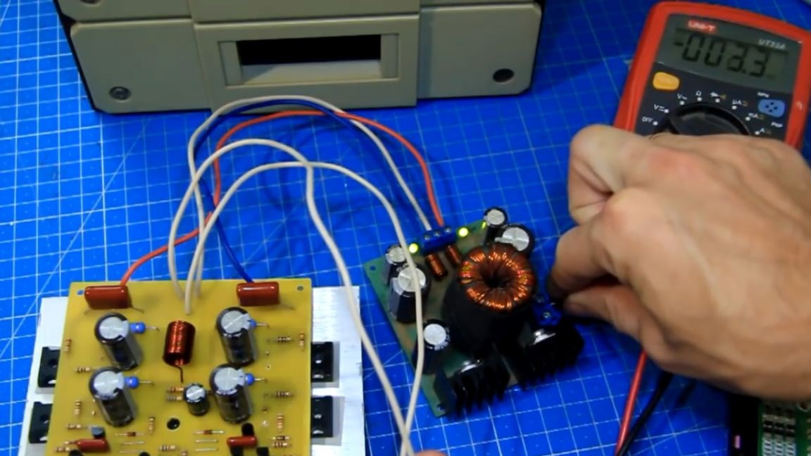
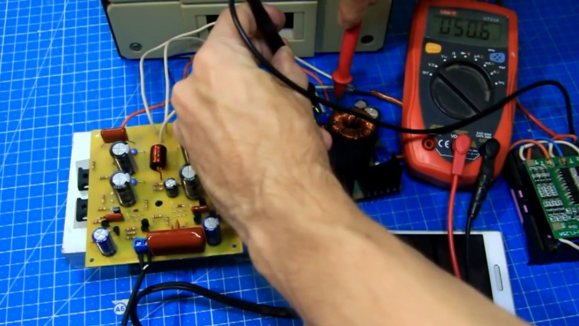
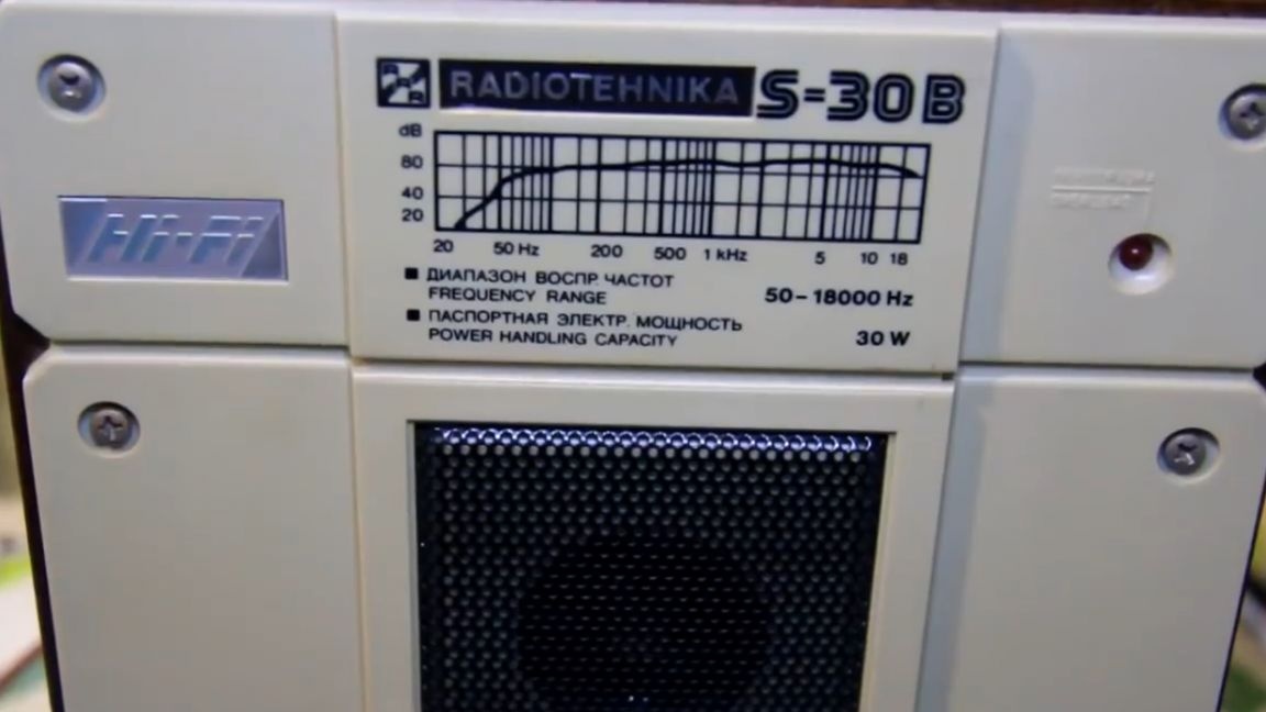
When the power was connected, nothing exploded, there was no smoke, there was no constant output from the amplifier either - this is very good, so everything is fine in the assembly and you can connect speakers. By the way, according to the test supply: at the input of the inverter, the voltage is about 12V, and at the output 50V with a midpoint. The Radiotehnika S-30B will play the role of the test speaker; we connect it to test the output of the assembled amplifier. Now we try to supply power with acoustics.
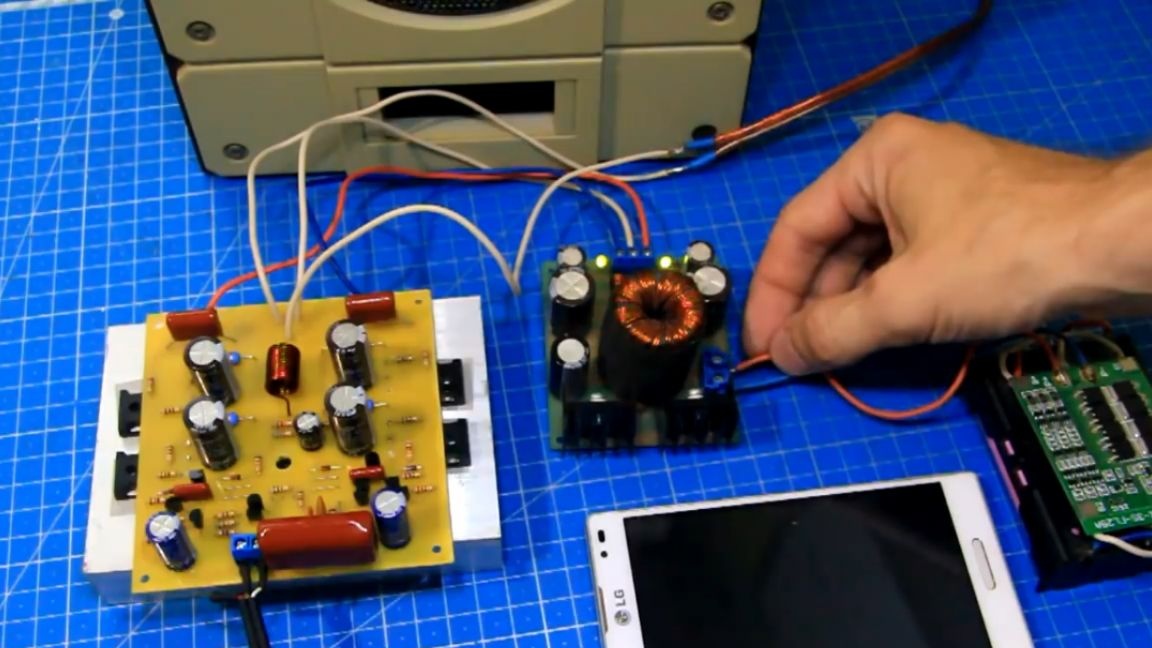
Everything worked. There is no clap when turned on and there is no noise either. Now you need to try to apply a sound signal to the input of the amplifier. There is a reaction at the input of the amplifier, the phone will be the sound source, we will turn on the test track (you can estimate the approximate sound quality by watching the author’s original video, link at the end of the article).
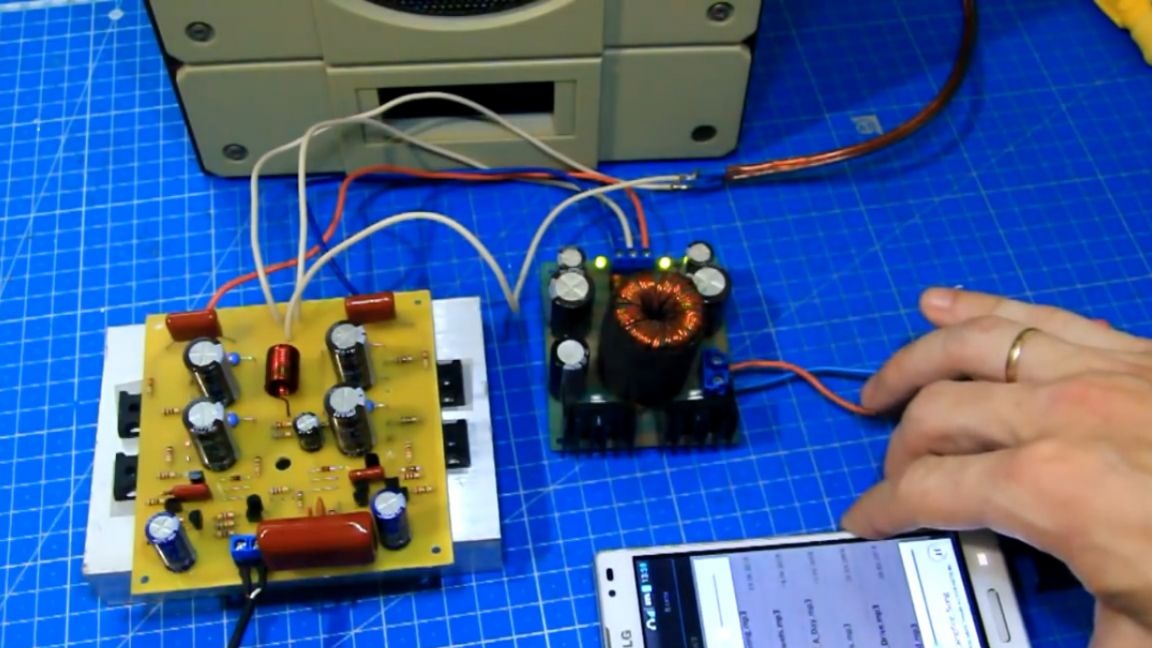
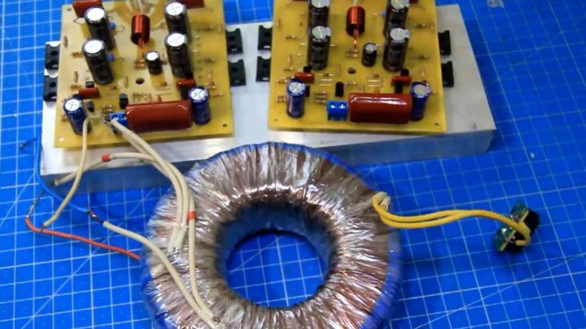
So, our homemade sound amplifier really worked and plays. So, if the amplifier is assembled correctly, then it works and plays, which of course cannot but rejoice. The circuit is normal and working, and then you can already think about how to assemble a ready-made amplifier and how these assembled modules will be placed vertically or horizontally in the case.
You can also pick up a normal sized radiator. In order for these amplifiers to develop the declared power, they must be provided with normal power either from a transformer or from a switching power supply.
The output power, depending on the load resistance, the author (Ilya Stelmakh) depicted on the graph:

You can try to repeat and collect. The output power is really large, here the main thing is to find suitable speakers. Nevertheless, for beginners, this author does not recommend this amplifier. There seems to be nothing complicated here, but problems can still arise as there are a lot of details and it’s quite difficult to call it simple.Well, and much more time will go to find all the details. It’s rare when everything is in one store. On these boards, you can assemble a very decent ready-made amplifier. He will play very loudly. Well, that’s all. Thank you for attention. See you soon!
Video: