
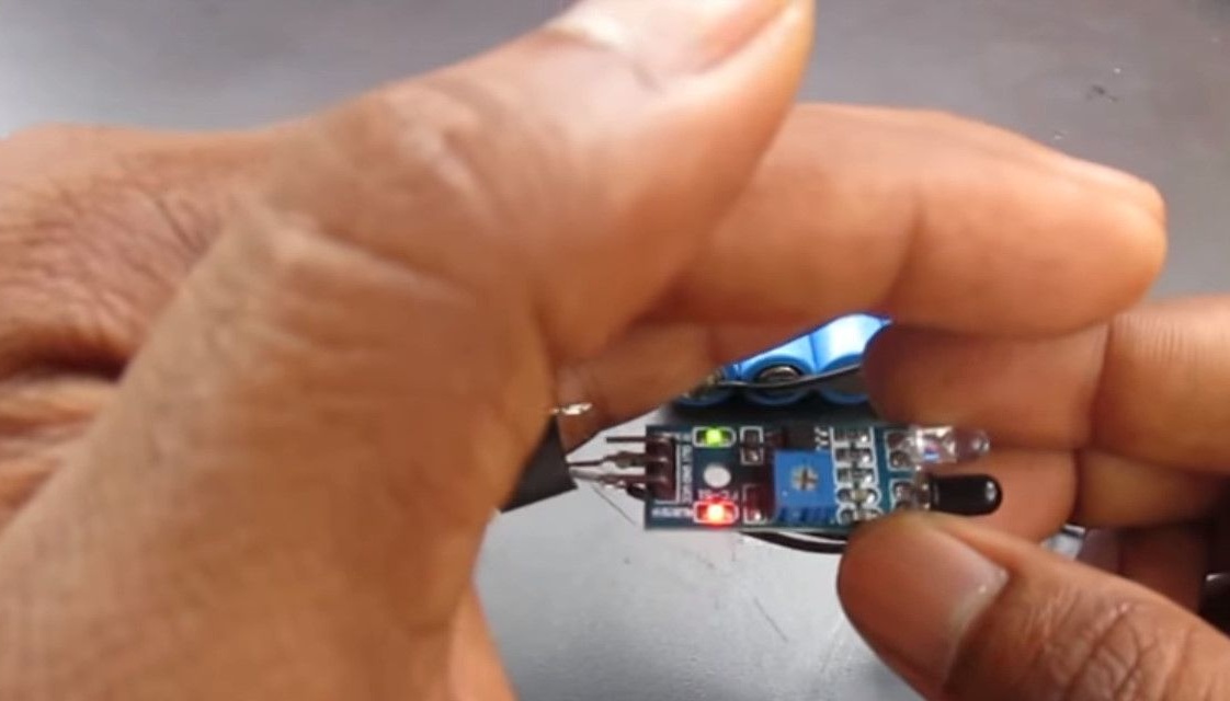
In this article, the author of the channel "Make Your OWN Creation" will show you how to make an active infrared sensor that responds to the intersection of a conditional line. For example, when passing through a doorway or at a small distance from it.
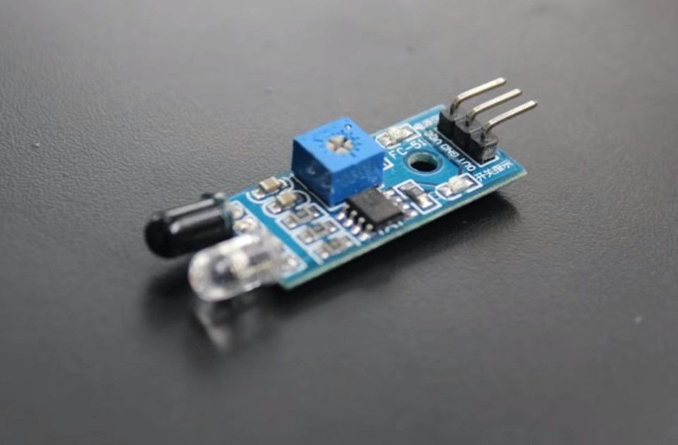
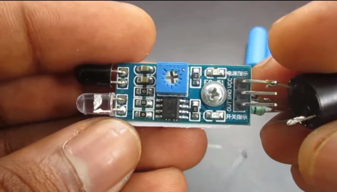
This sensor will be useful, for example, for store owners, it will allow you to hear in time about the intersection of a certain area by the buyer. It is wireless and standalone. Can be installed at any desired location. It also does not require the installation of mirrors, like laser systems. The principle of operation is the emission and reception by the controller of the reflected signal from the object. For this, a transmitting infrared LED and a receiving photodiode are installed on his board.
The range of the beam is adjustable.
After reading this article, almost any master who knows how to use a soldering iron at least can repeat this device.
The number of required parts is minimal.
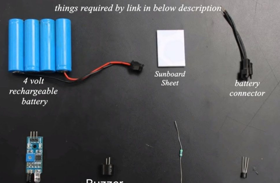
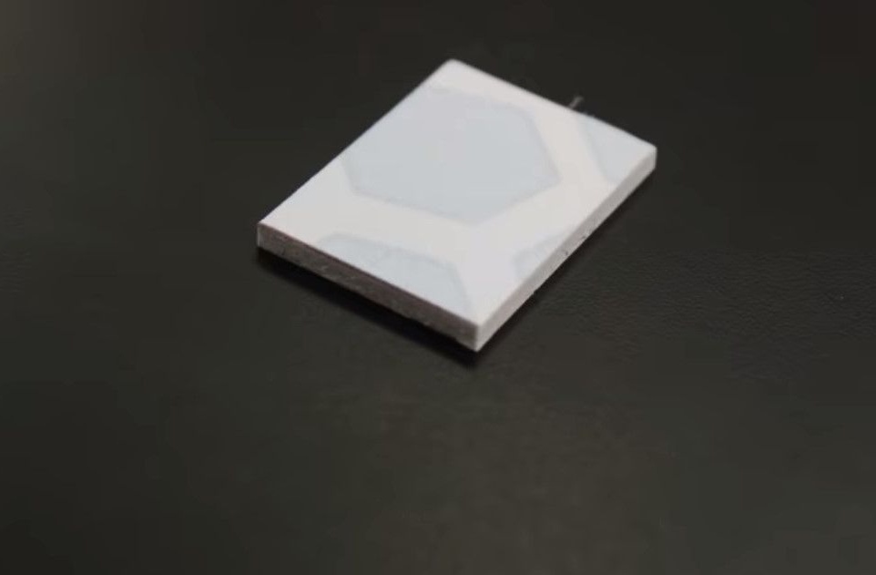
1. Infrared module reference to it here.
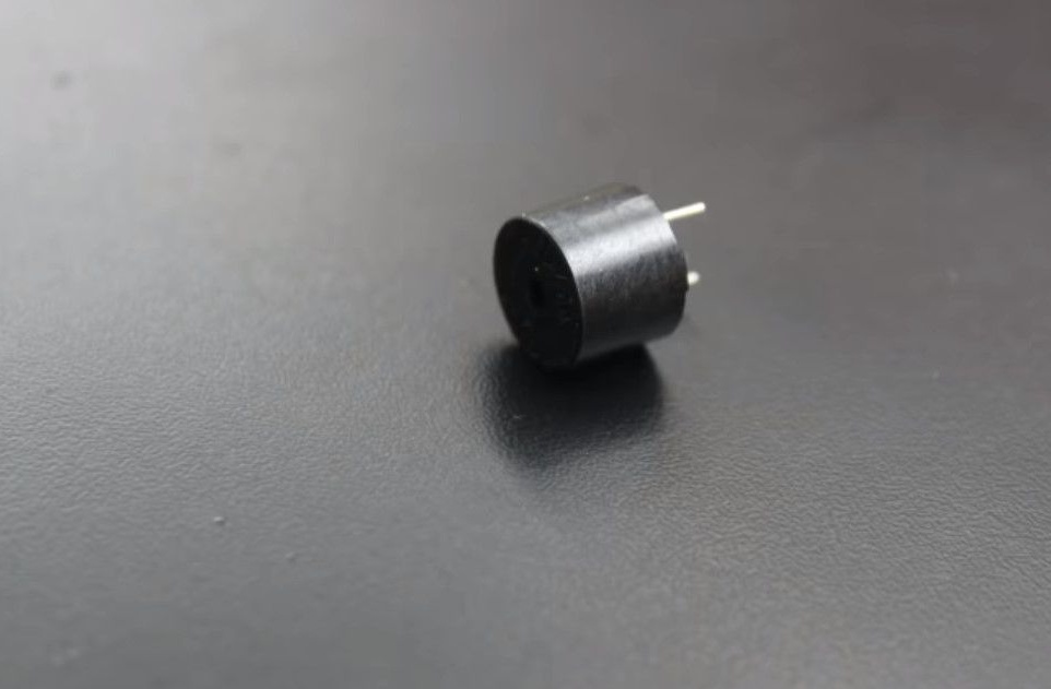
2. Buzzer, or squeaker, voltage 5V here.
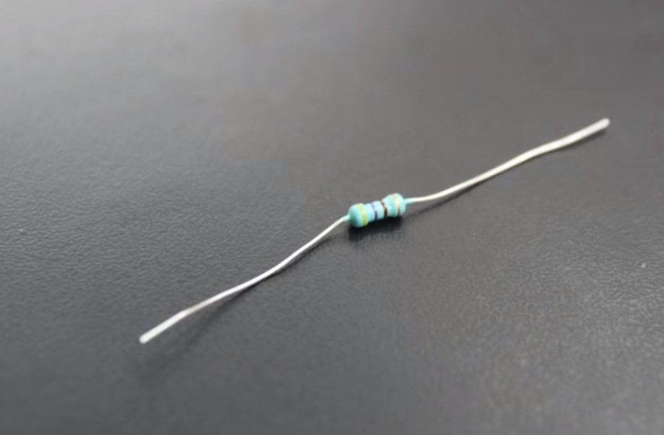
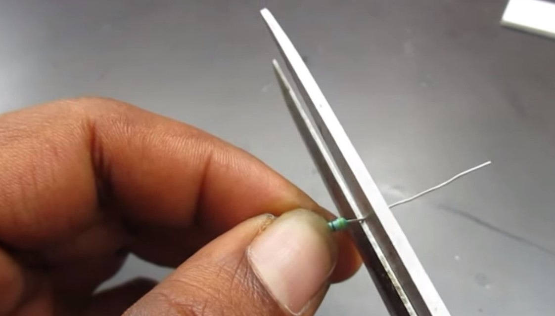
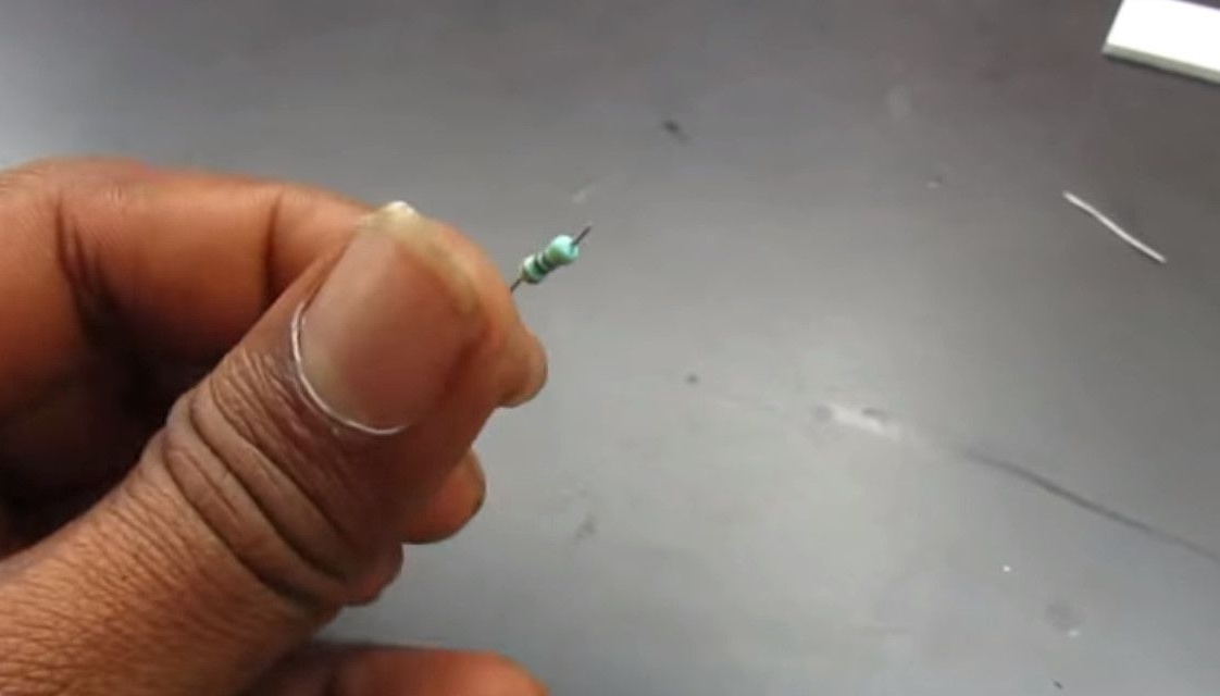
3. 4.7 ohm resistor.
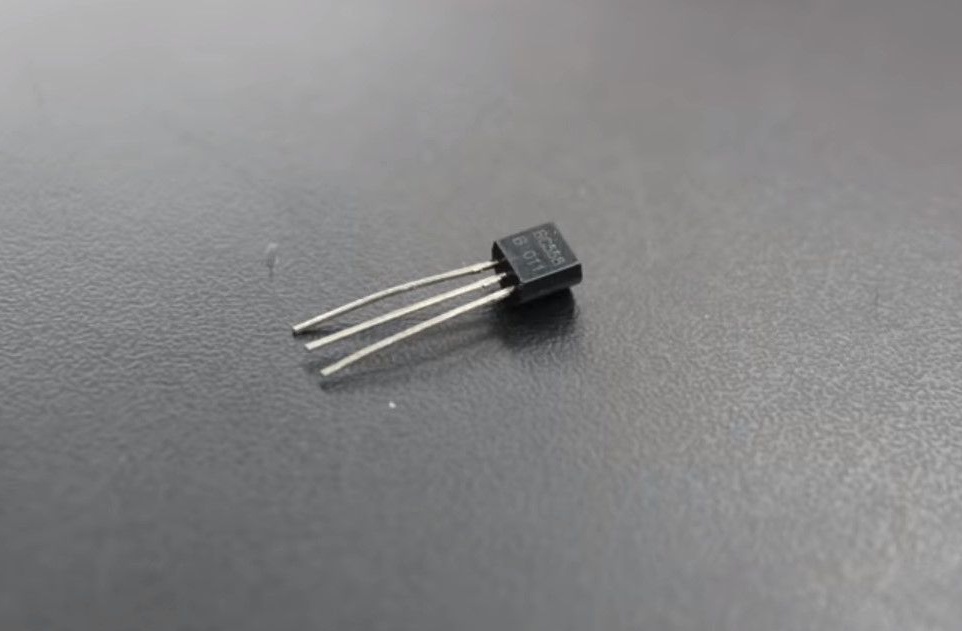
4. Transistor BC558.
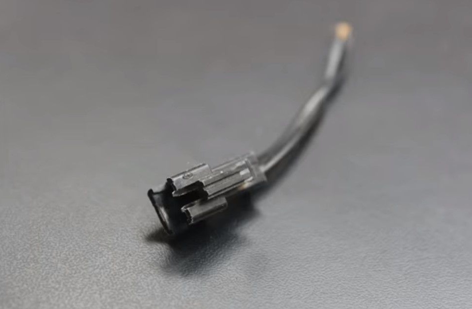
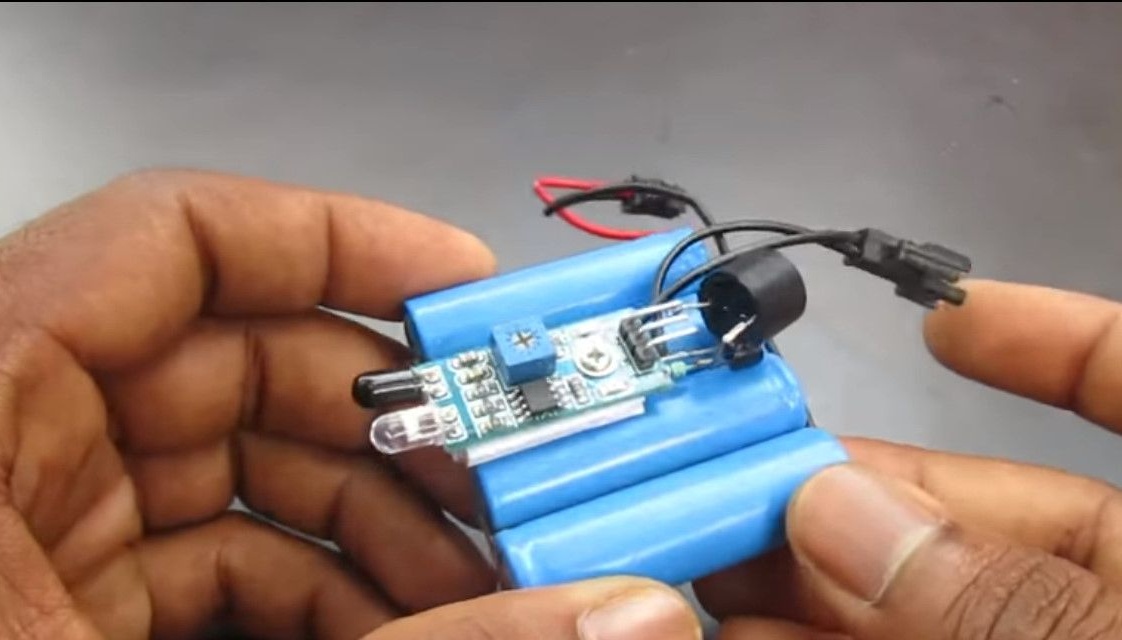
5. Battery connector.
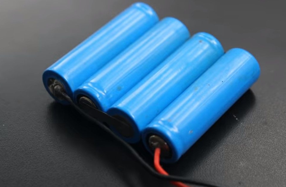
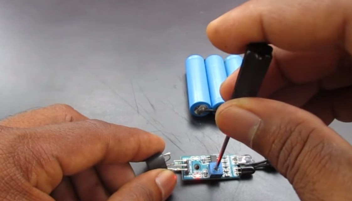
6. Battery assembly voltage of 5V, this can be taken from a radiotelephone. It can also be replaced with any other battery, for example, the most popular 18650.
7. Power button (the author did not use it, probably each time he will have to disconnect the connector from the battery).
P.S. all components can be purchased at the radio market or store electronic components.
Of the tools and consumables you will need:
1. Soldering iron and solder.
2. Side cutters.
3. A Phillips screwdriver, a small self-tapping screw.
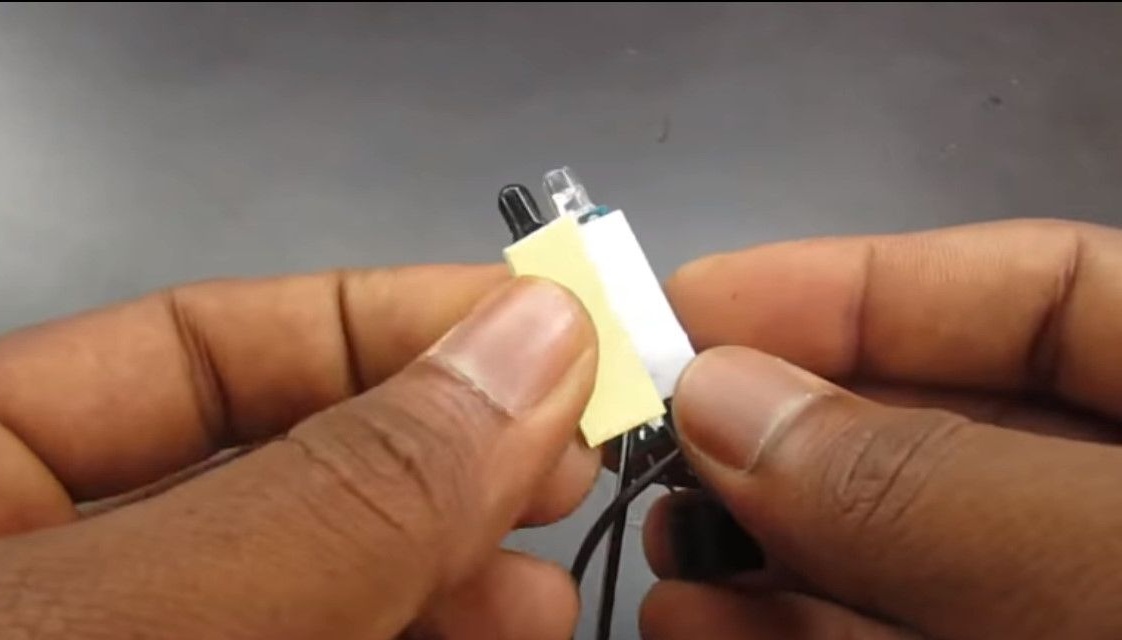
4. Double-sided tape.
5. A small piece of foamed plastic.
So, assembly process.
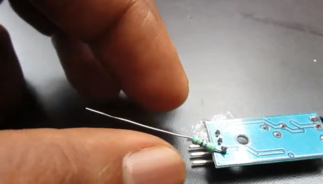
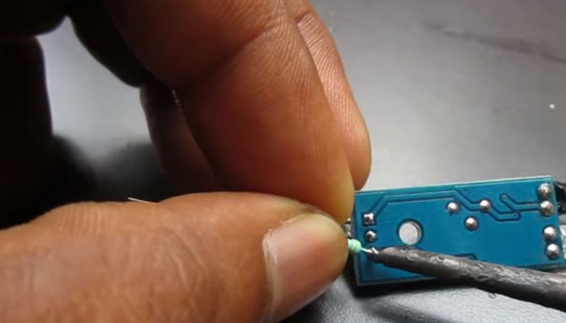
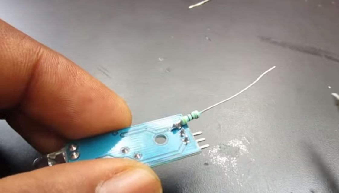
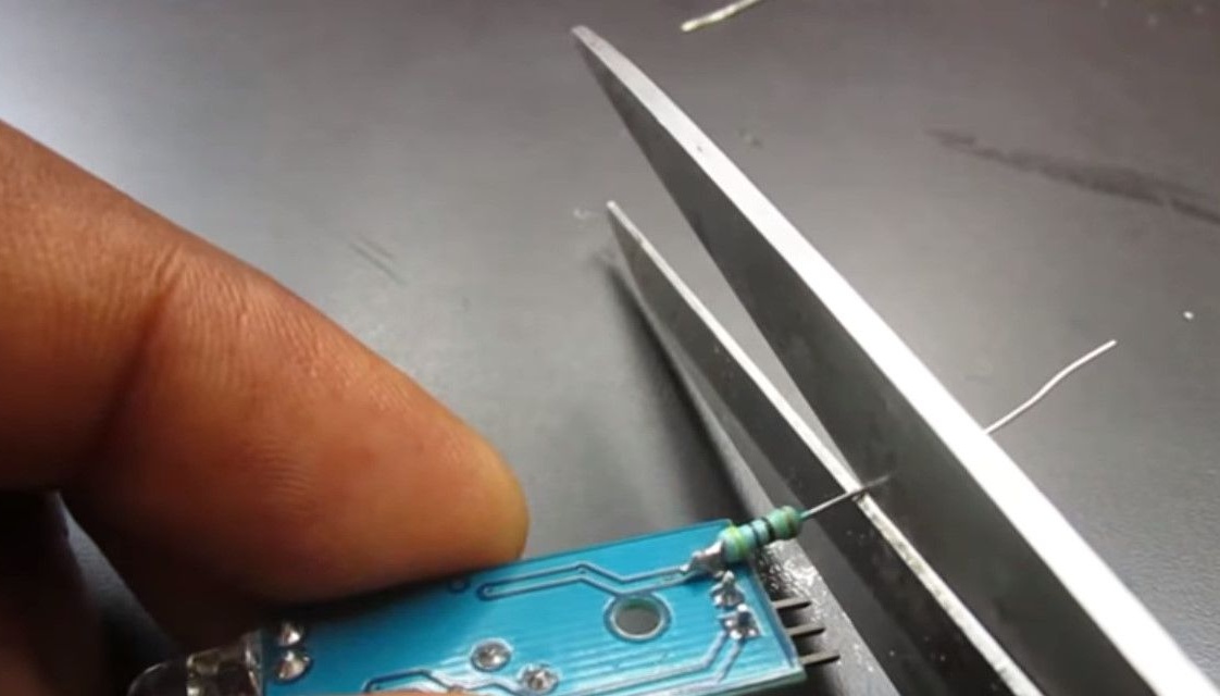
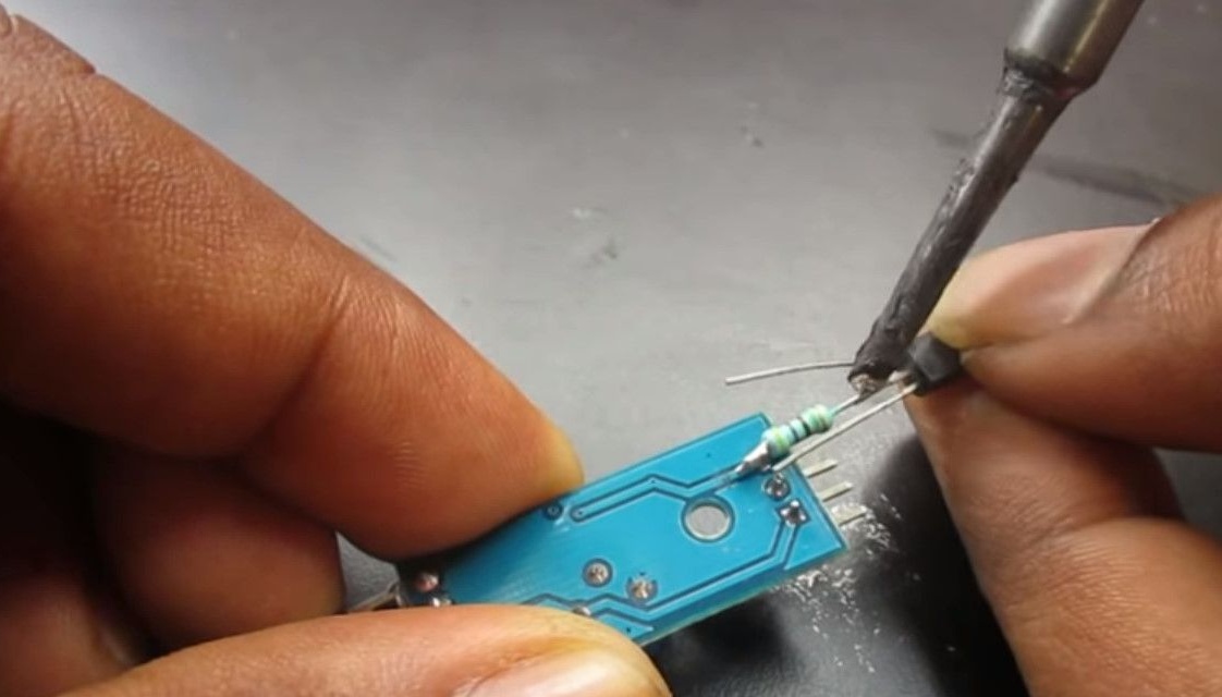
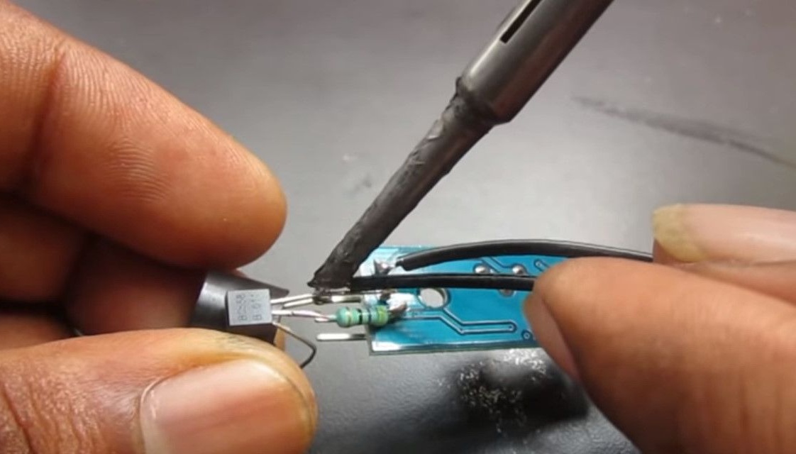
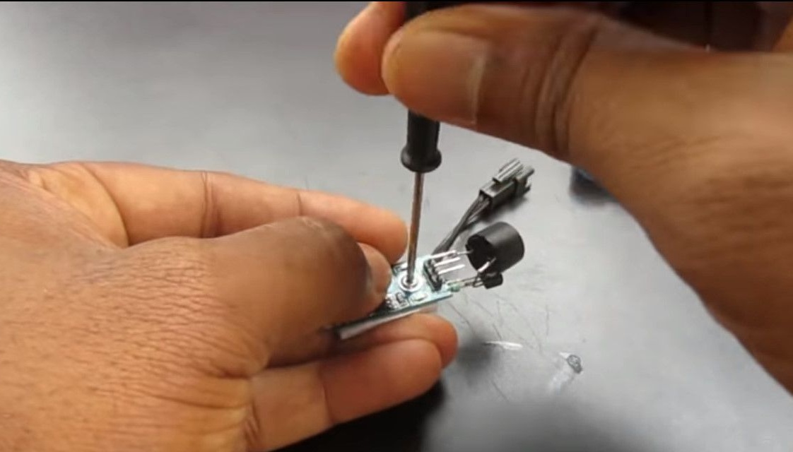
Shortens the resistor leg, solders it to the OUT pin (output) on the board, also cuts off the excess.
Now, having shortened the middle leg of the transistor, the base solders it to the resistor.
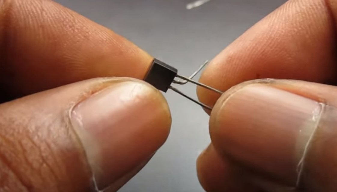
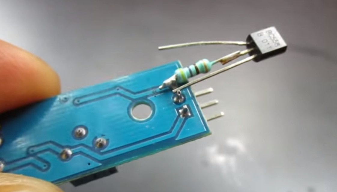
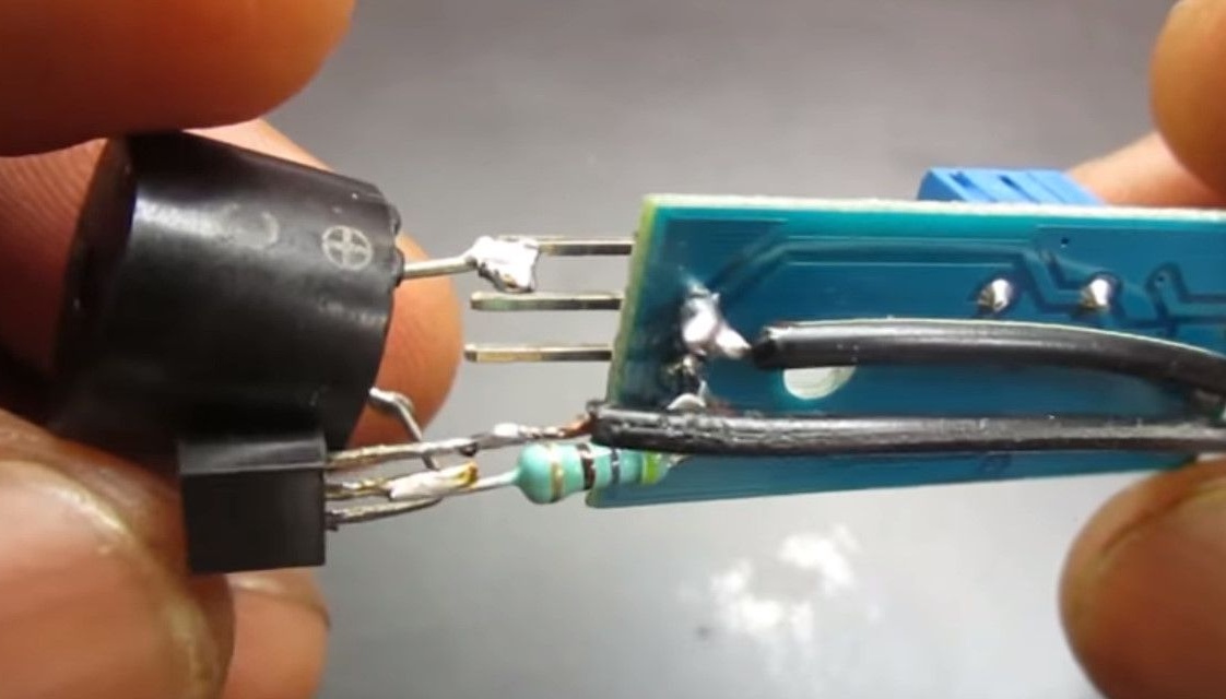
The right or third leg, the emitter, (ATTENTION on the position of the transistor!) Is soldered to the negative terminal of the GND board.
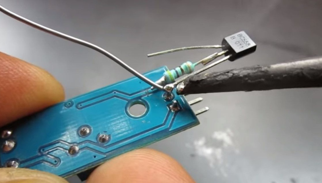
The positive tweeter contact is soldered to the positive contact on the VCC board.
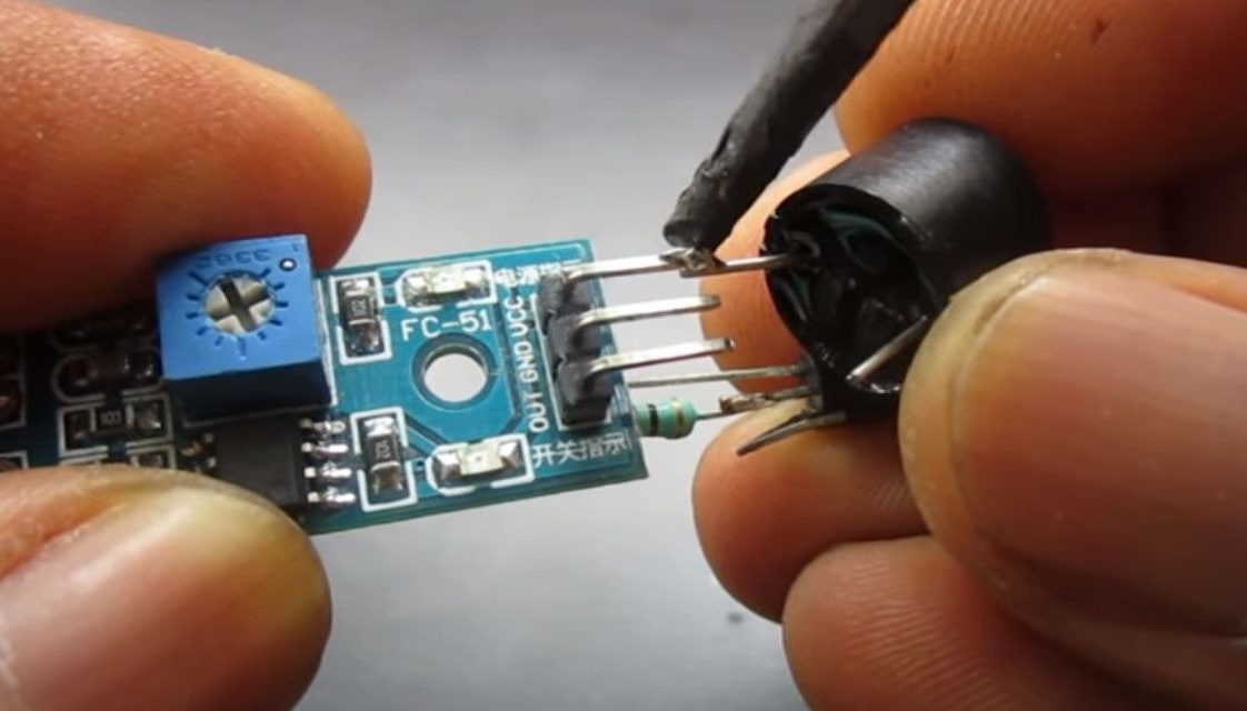
Negative tweeter contact - to the transistor collector, first, left leg.
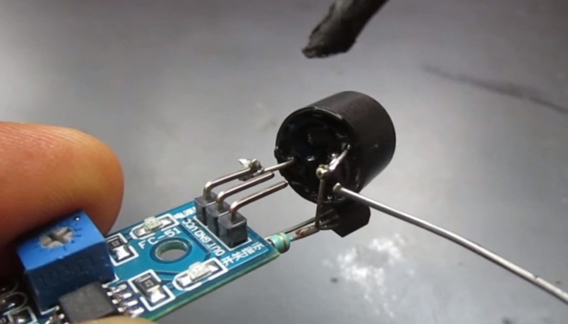
Now the turn of the power connector. The positive wire is, respectively, to the VCC board, the negative wire to the GND board.
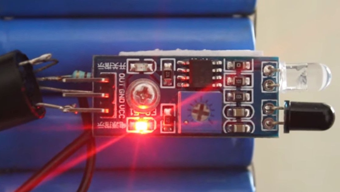
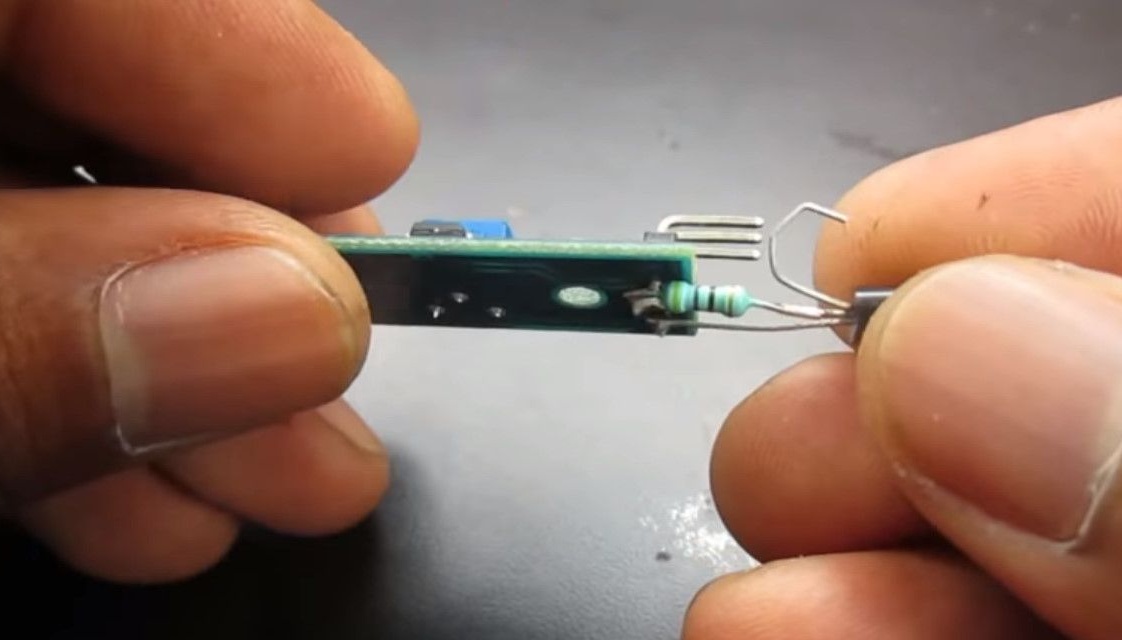
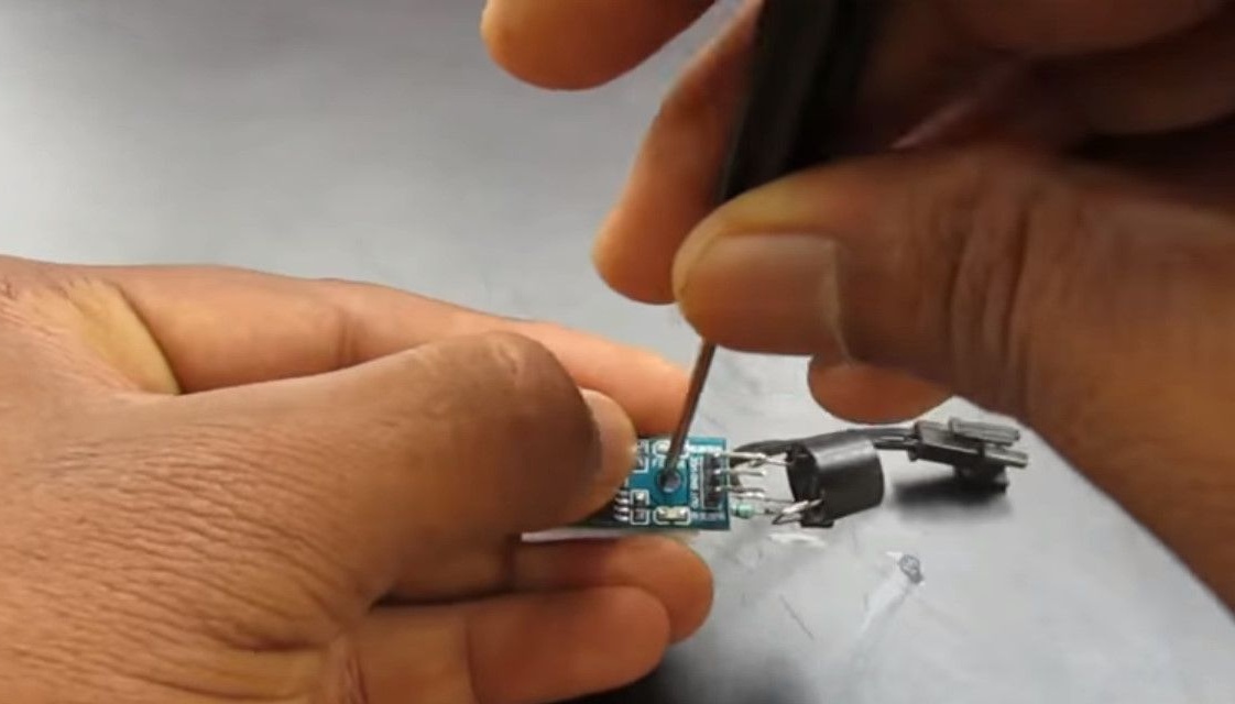
It connects the battery and adjusts the sensitivity with the help of a tuning resistor, manually changing the range.
Poking a small hole in the plastic with a screwdriver, screwing the screw in, fixing the board.
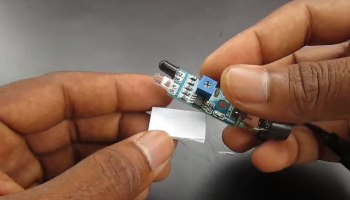
Further, double-sided tape is glued to the plastic and connected to the battery, it checks the operability.
And again with the help of adhesive tape mounts the device to the wall.
Everything is ready, now no one will pass the door, unless you can crawl =)

Here is the normal situation.
And here already worked.
I hope you find this simple circuit useful. I wish the author to make a case for the device.
Thanks to the author for a simple but useful idea.
All good homemade!