
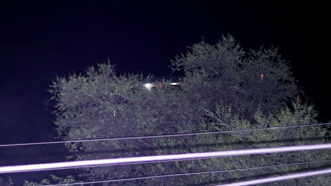
Good day to all dear friends! In today's article, I would like to show you a very interesting idea about homemade. Namely, how to make a simple but at the same time very powerful flashlight at 100 WT! The main feature of this homemade product is not in simplicity, but in compactness. This will be the "most" compact flashlight at 100 WT. This lamp will probably come in handy not only for those who like to travel and go in for tourism, but also for those who just sometimes go outdoors. Also, this flashlight is useful to motorists, for example, if something breaks at night and you can’t do without lighting. This lantern can illuminate the entire street, forest, forest road, etc. I also want to note quite a few important detail that it is not recommended to use this lamp in a small room as it is very harmful to the eyes. In general, we will not delay with a long introduction, let's go!
For a home-made LED flashlight, we need:
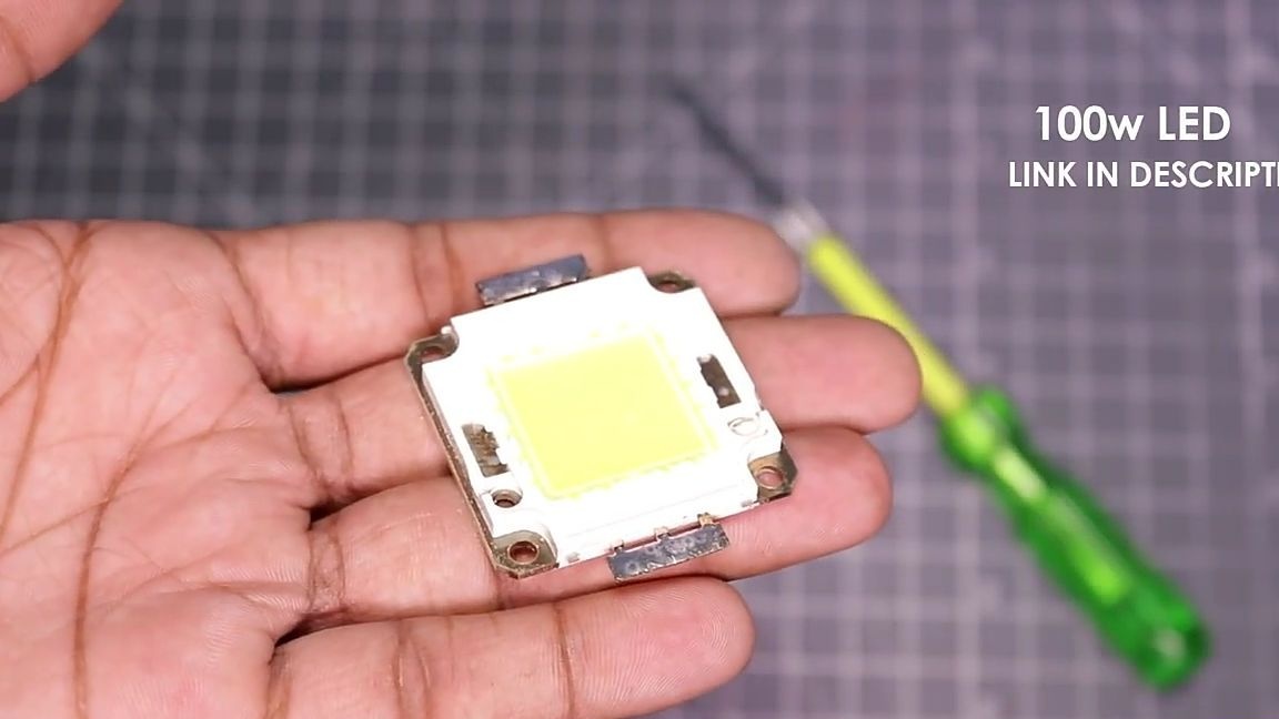
- 100W LED array
- Radiator
- fan
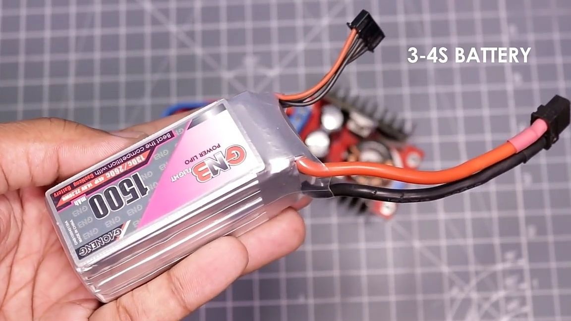
- Li-po 3-4s (11.1-14.8V) battery with xt60 connector (as it is the most convenient)
- xt60 connector
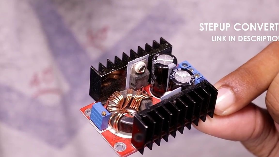
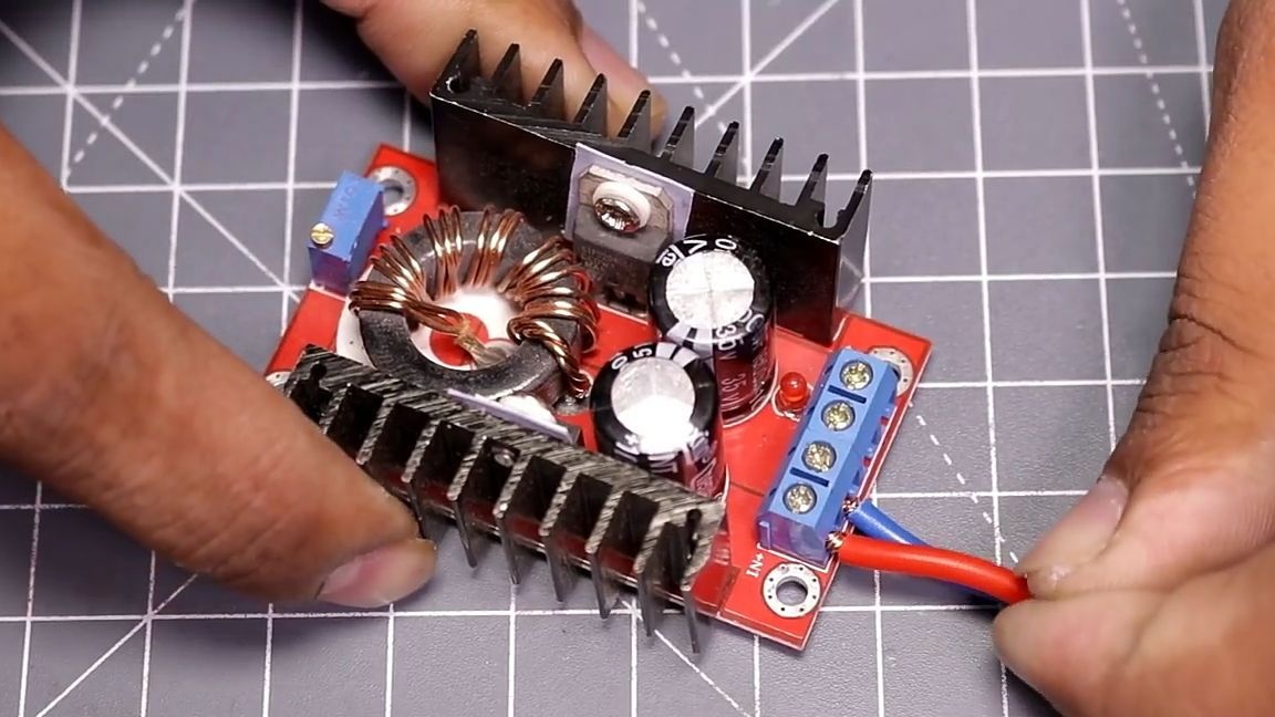
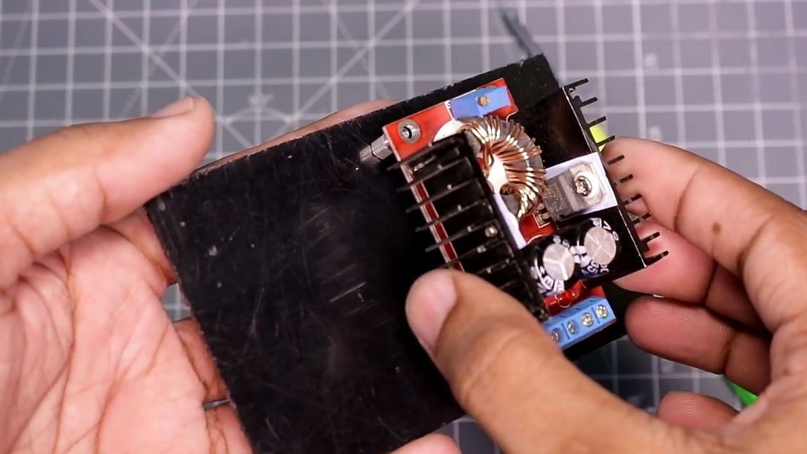
- Boost DC / DC Converter
- 44mm lens
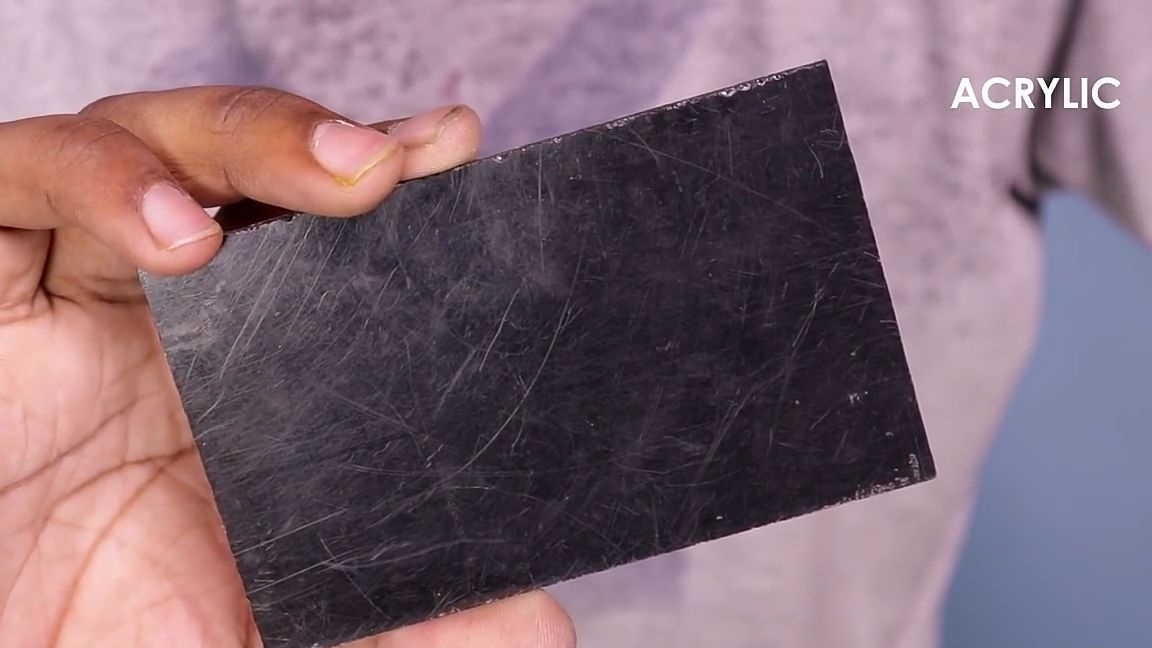
- A piece of ABS plastic or acrylic
- Screws and nuts
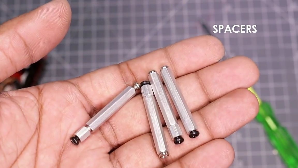
- Stands for printed circuit boards
- Not a big aluminum plate
- Power wires
- Thermal grease
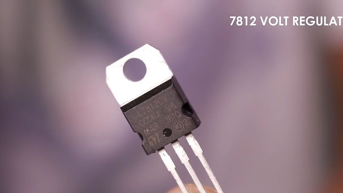
- Voltage stabilizer 7812
- The switch.
From the tools you will also need:
- soldering iron
- Super glue
- Drill with drills
- screwdrivers
- marker
- Multimeter (enough and a volt meter).
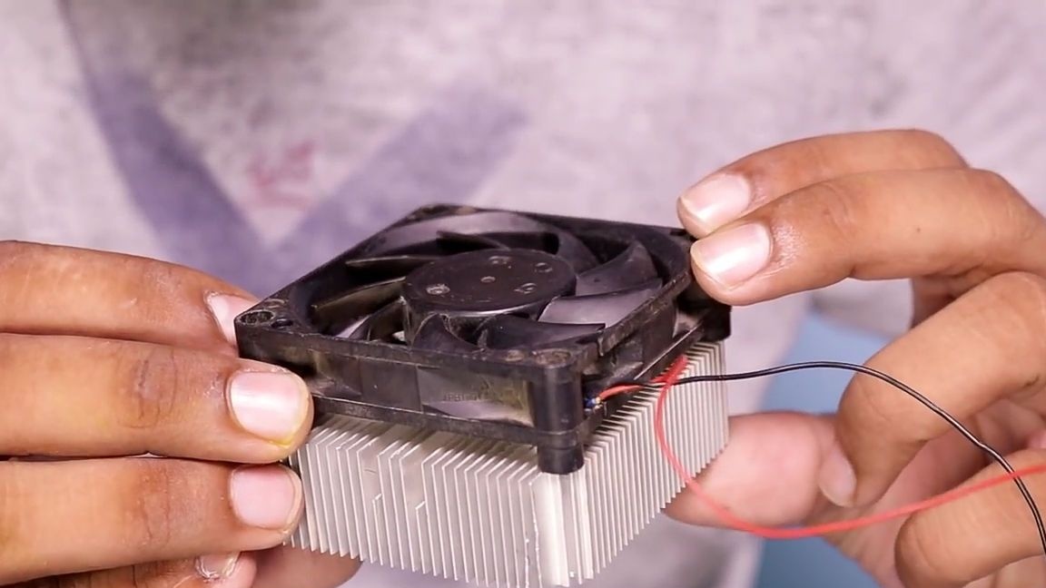
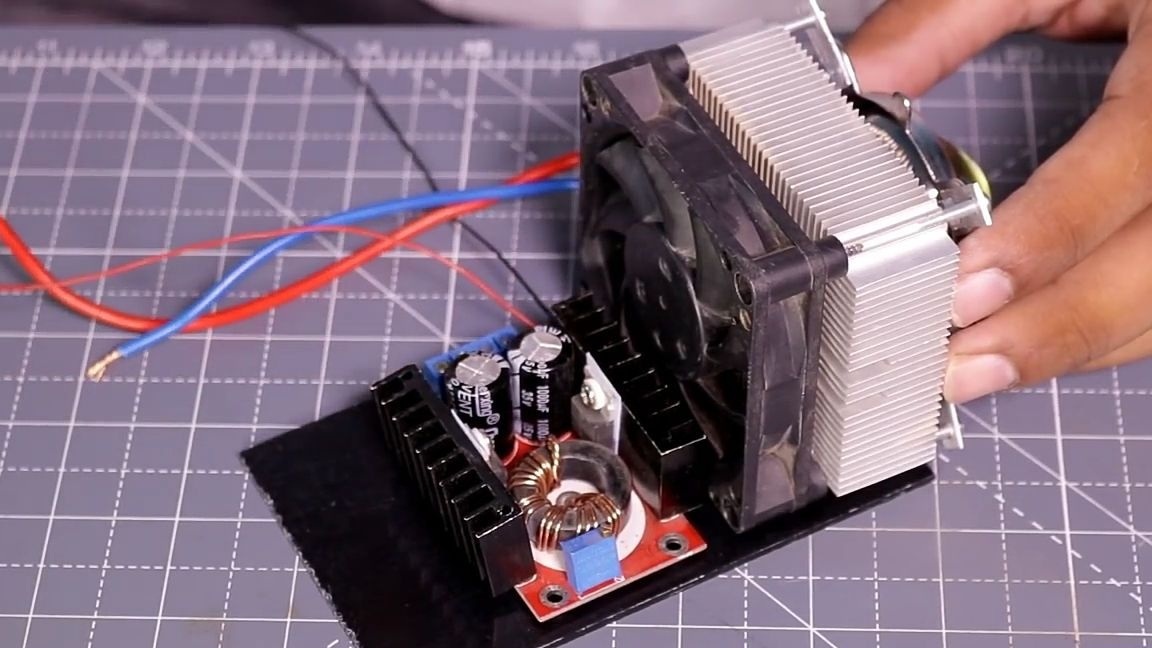
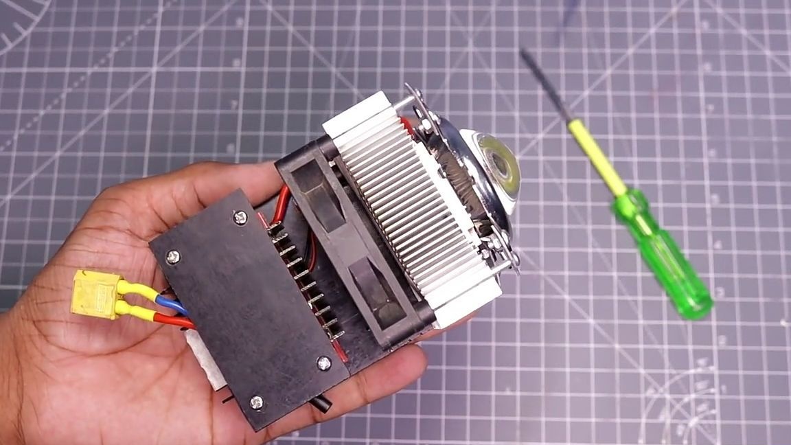
Since the LED matrix will overheat, it should be cooled, and using active cooling. To do this, we should choose a suitable processor cooling radiator. Since almost no one is using such an outdated type of PC cooling, such radiators are easy to find in the repair of household appliances. In addition to the radiator, we need a fan (cooler) to it.
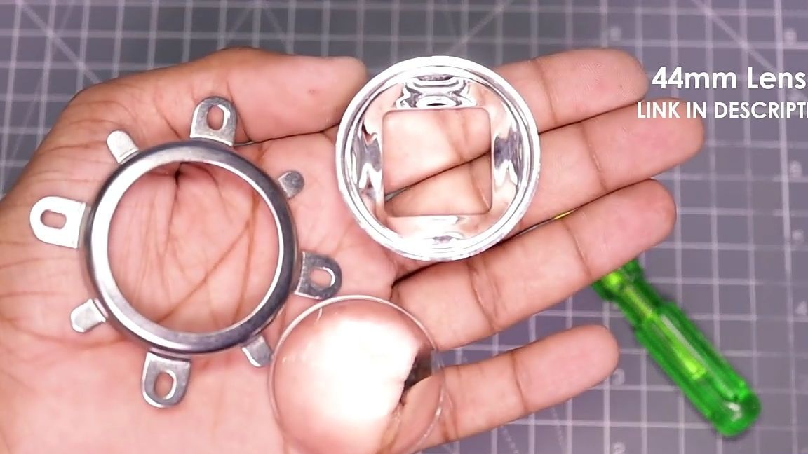
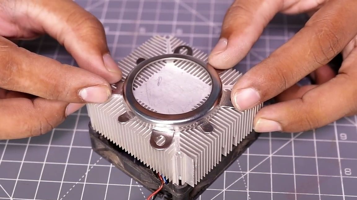
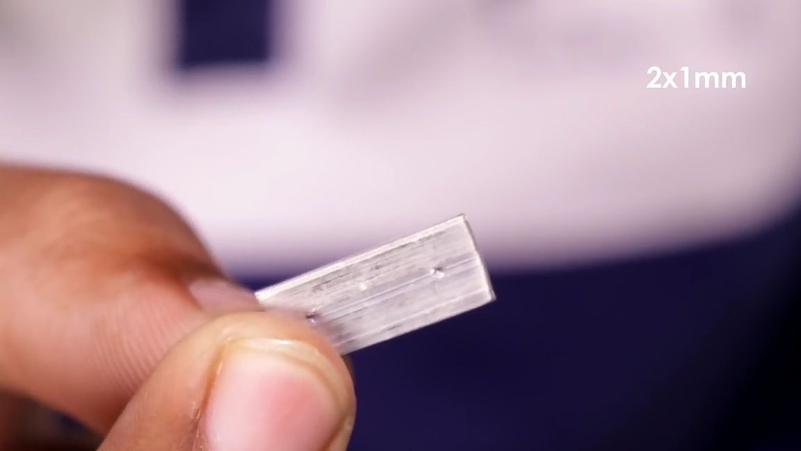
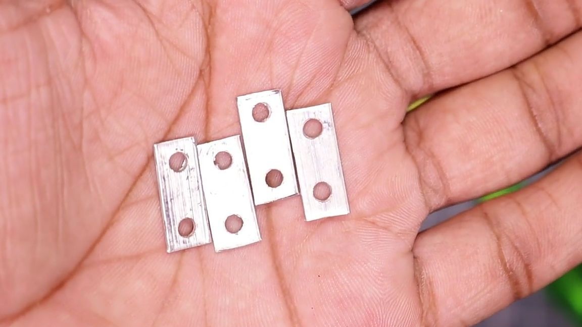
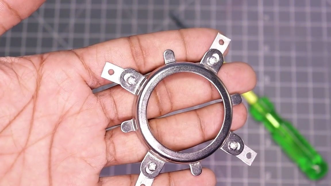
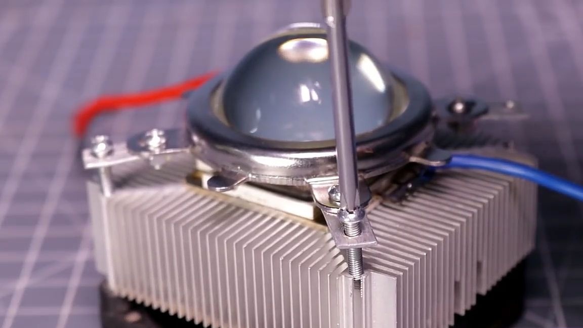
After you found a suitable cooling radiator. It should be sized to fit the lens you have taken. To do this, you need to take the mount itself and place it exactly in the center of the radiator on the side where the LED matrix will be located. And we see that the mounting holes on the mount and on the radiator do not match. To do this, to fit the holes from the aluminum plate, appropriate spacers should be cut. In our case, the size of the spacers is 2 × 1 mm. Install spacers.
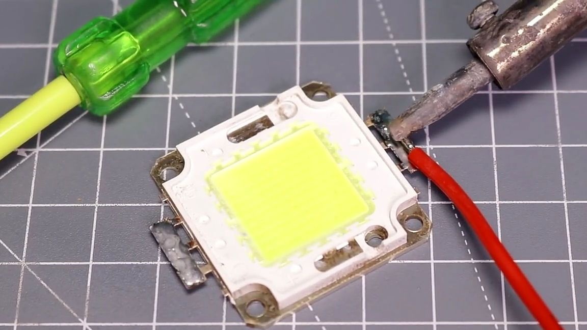
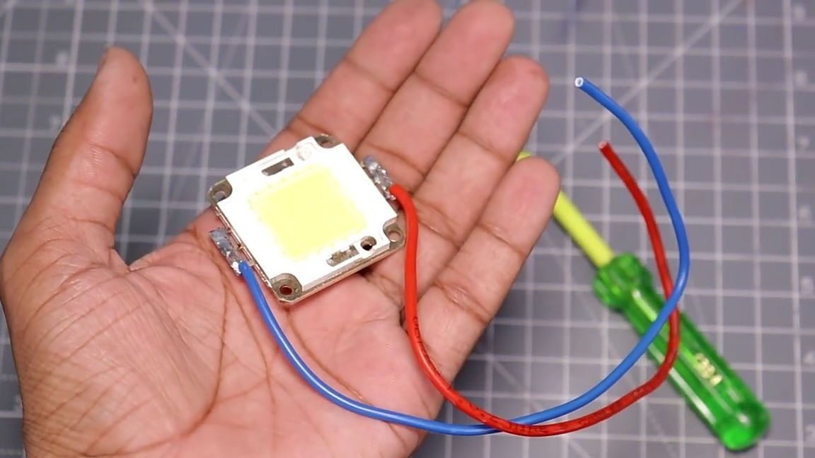
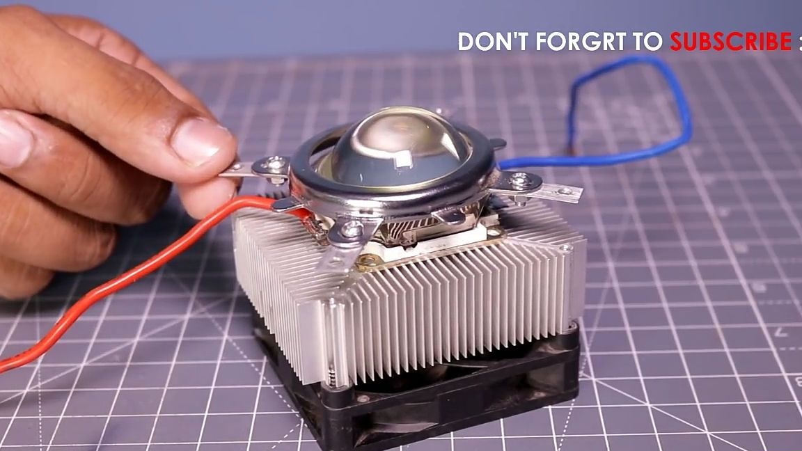
Then we need the LED matrix itself. Two power wires should be soldered to it.Before soldering the wires to the matrix, they should be tinned. Soldering should be a well-heated soldering iron and very quickly, as it is likely that you will overheat the matrix and it will fail.
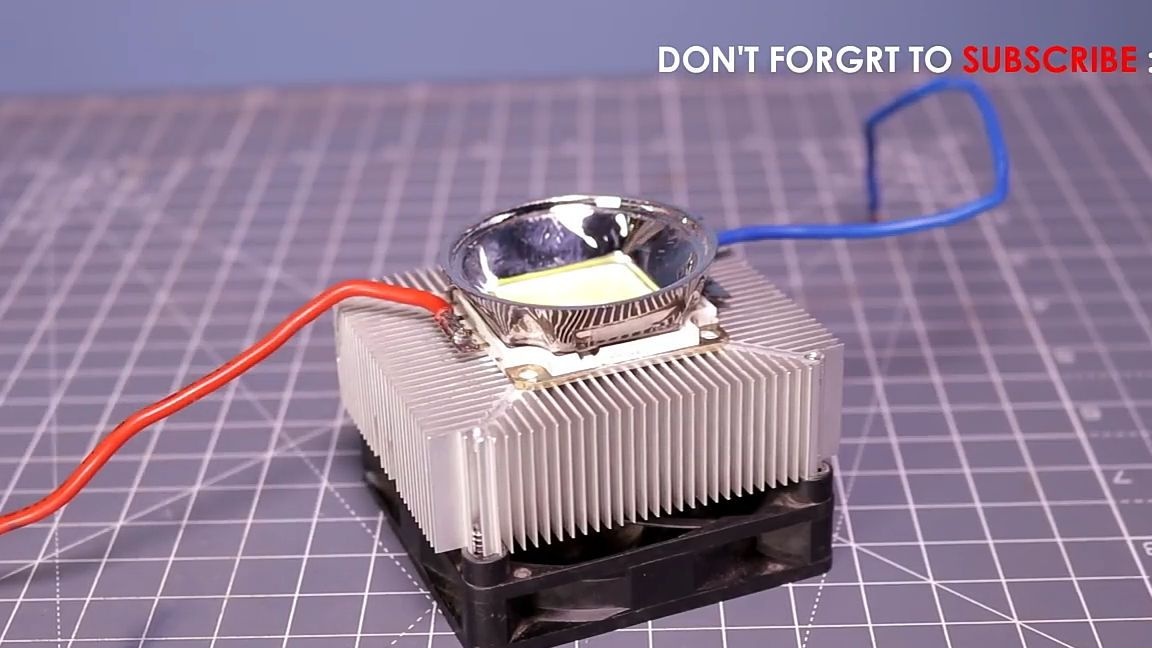
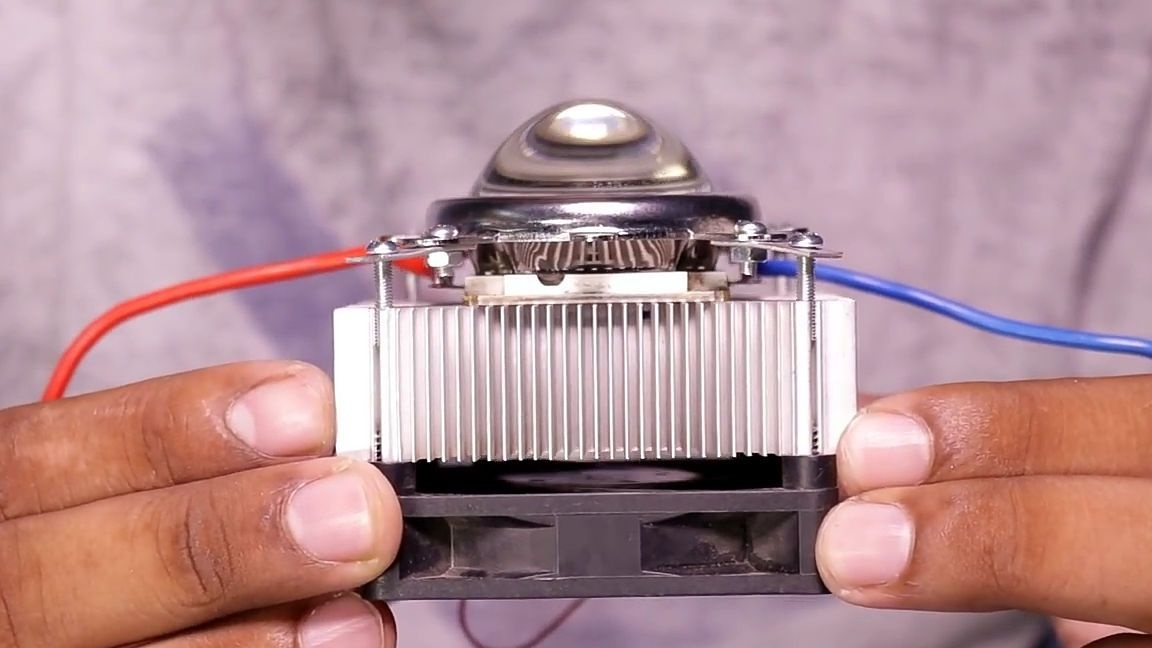
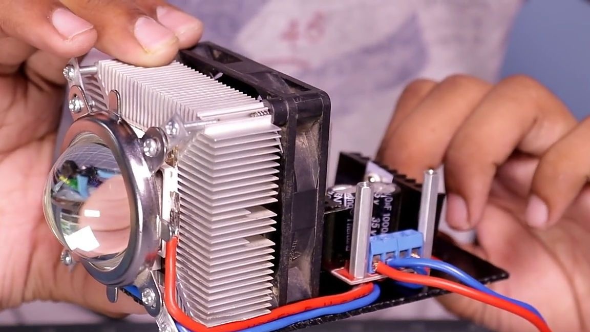
After that, the LED matrix should be connected to the cooling radiator. To do this, first apply a thin layer of thermal grease to the radiator, and then glue the LED matrix. Next, on top of the LED matrix, we install the lens and mount, which were previously prepared for installation.
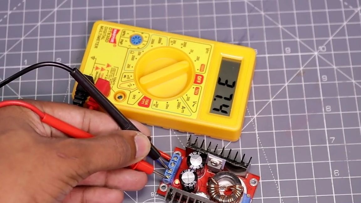
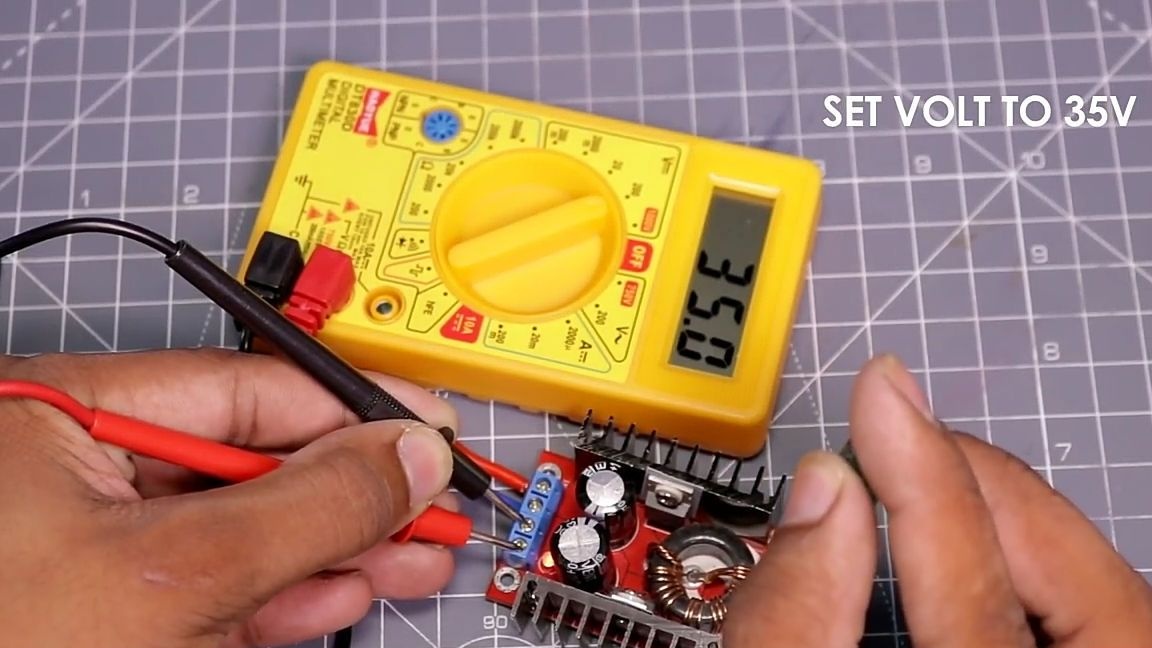
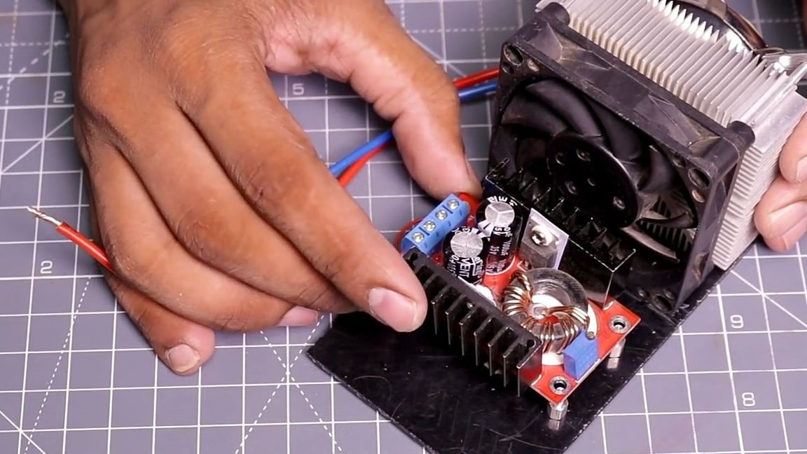
Then take a boost DC / DC converter and set it up. To do this, according to the polarity, install the xt60 connector on the input of the board, and on the output a multimeter. We insert the battery into the connector (11.1 - 14.8V) and the potentiometer built-in on the board, set exactly 35V at the output.
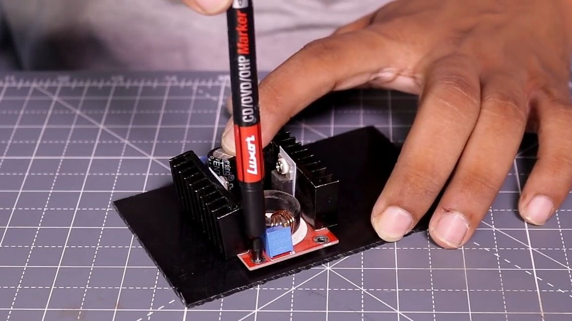
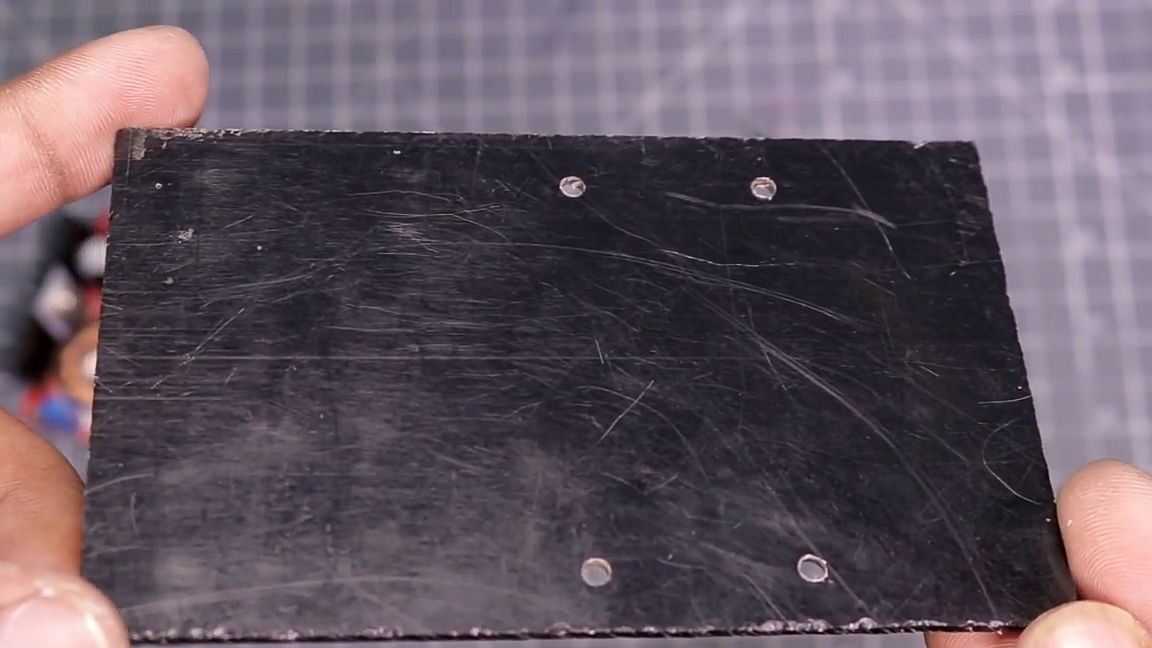
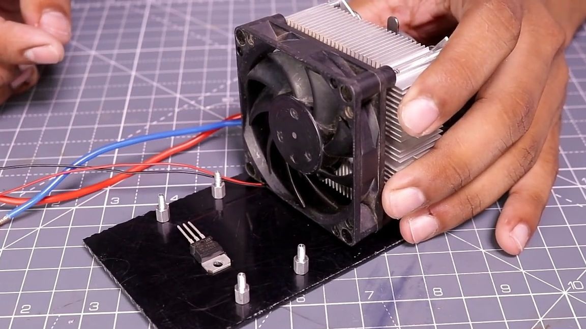
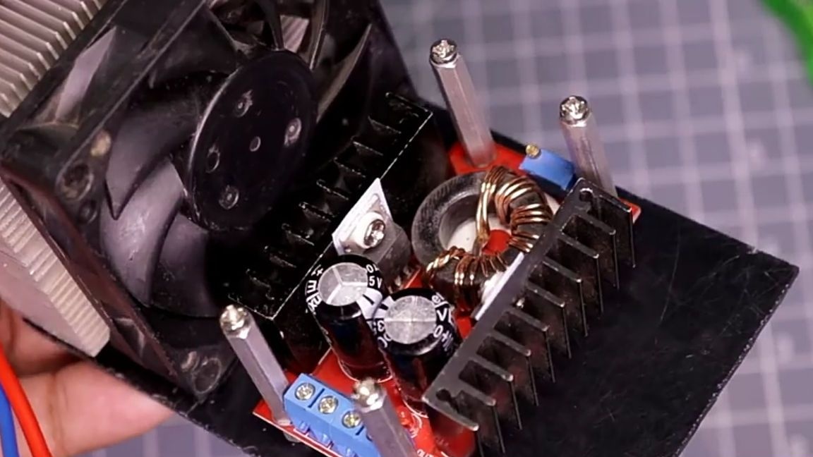
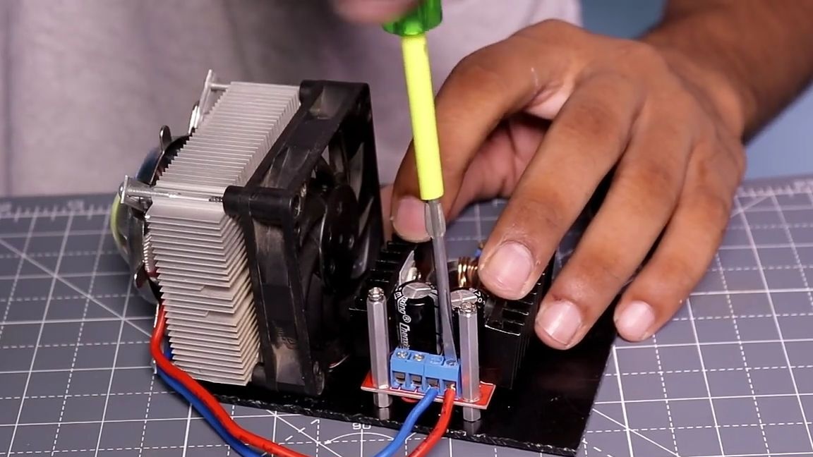
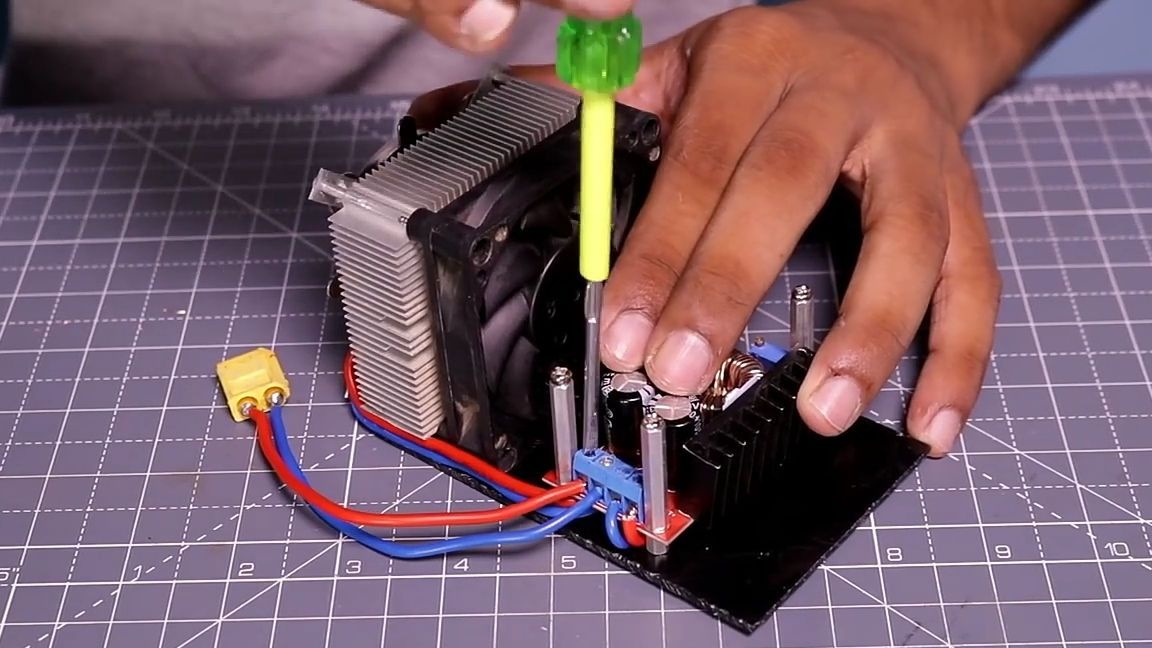
After the above actions, it is time to establish everything on the basis. As a basis, we will serve as a rectangular piece of acrylic of a suitable size. First, install a boost converter. To do this, we apply a radiator with a lens to the edge of the acrylic as shown in the photo below. For the radiator, we apply the converter itself and leave a marker under the mounting holes with a marker (this arrangement of the board will make it possible to use the cooling fan more effectively, since it will cool not only the LED matrix, but also the converter). We drill through holes and install special racks for mounting printed circuit boards.
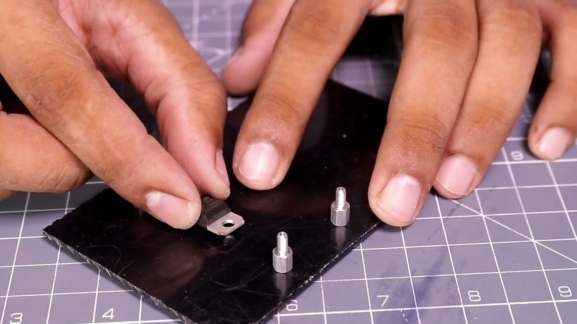
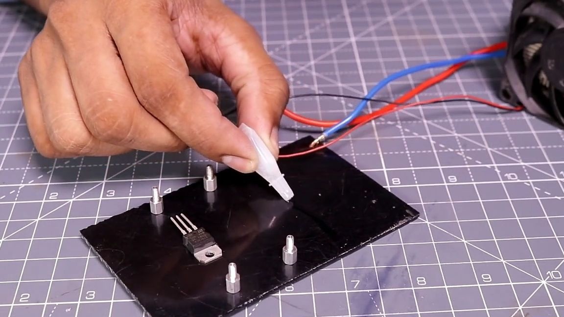
Before fixing the board on the base, you should think about powering the fan. To do this, take a voltage stabilizer 7812 and use super glue to glue it to the place indicated in the photo (while super glue is at hand, you can immediately glue the radiator in place). After the stabilizer is glued to it, solder the wires from the fan. Black wire to the central leg, and red to the right leg as to how it is glued (see photo). To the central leg is another wire no longer than 5 cm and the same to the left.
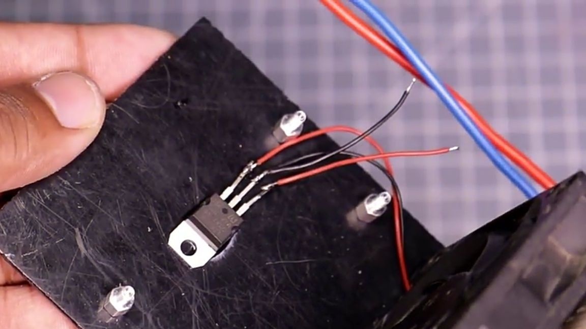
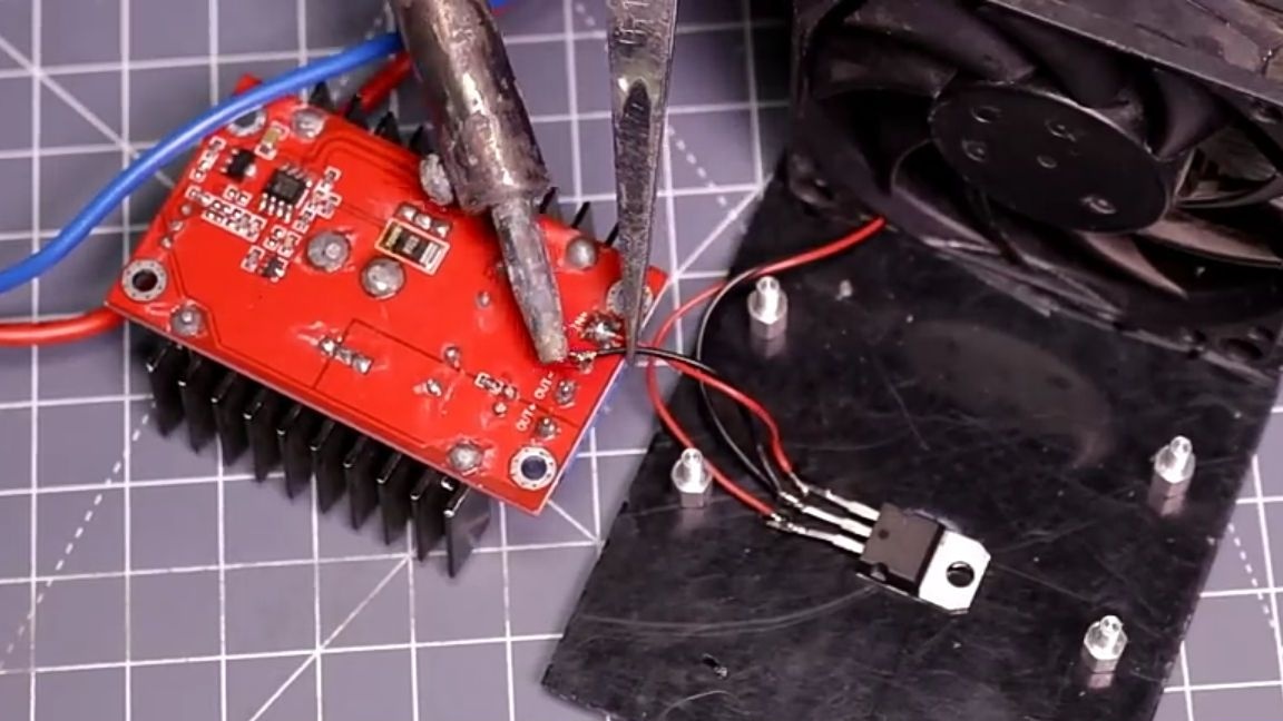
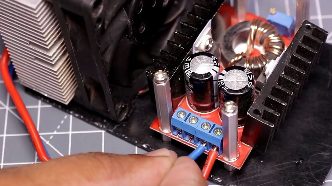
The wires that come from the voltage regulator are soldered to a boost converter. Solder should be where the input voltage is on the other side of the terminal, so as not to interfere with the power wire coming from the battery. Then we install the converter in its place.
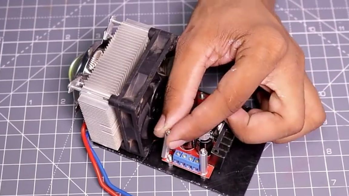
We will fix the board on the racks not with ordinary nuts, but with the same racks for printed circuit boards as in the photo.
Next, we connect the whole electronics. Namely, the wires from the LED matrix according to the polarity, are inserted into the output of the converter. And at the input, install the xt60 battery connector through the switch.
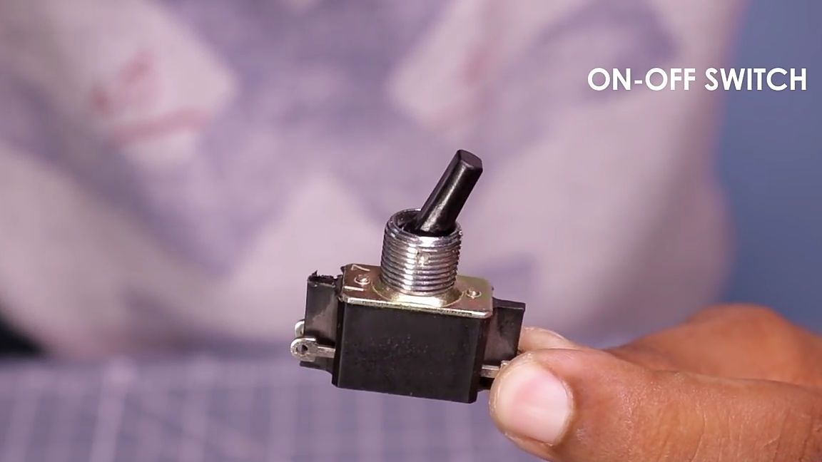
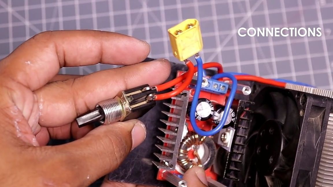
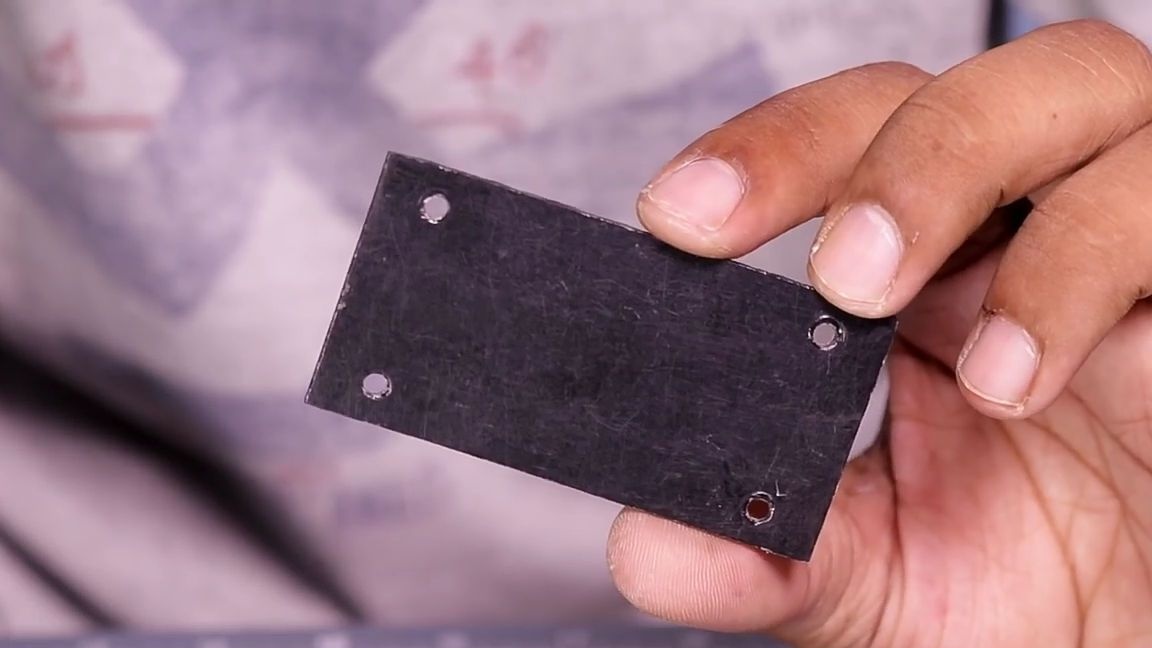
Then we cut out the acrylic plate, the size of which will be approximately equal to the size of the converter circuit board. And to it with the help of super glue I glue the switch. And the plate itself will be installed on the racks for the printed circuit boards that were installed earlier. But first, mounting holes should be made in the plate. To do this, just attach the plate to the converter circuit board and make marks, and then drill through holes.
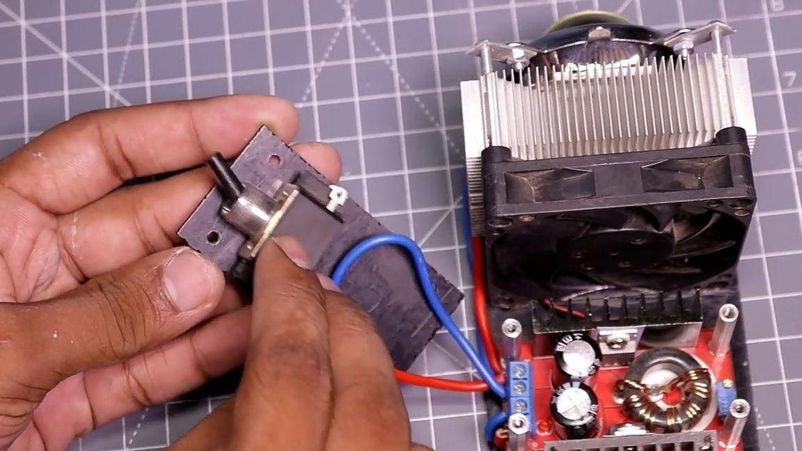
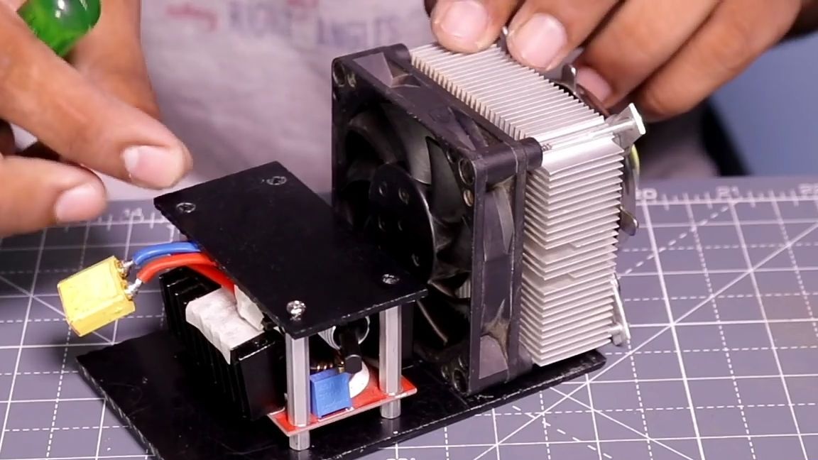
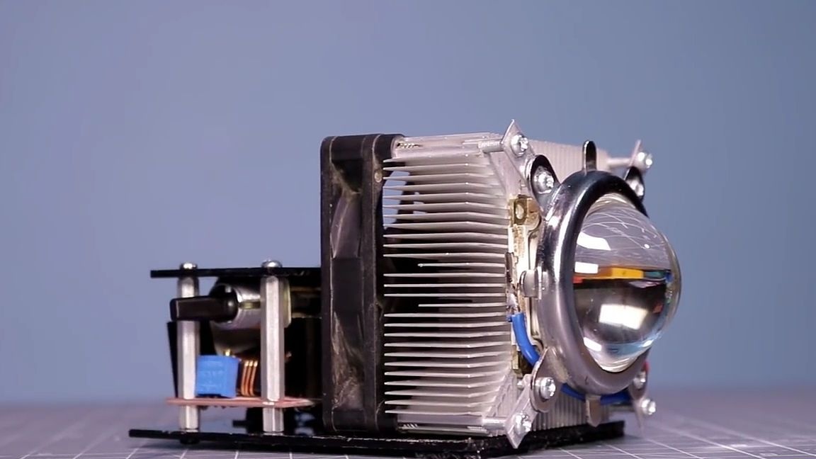
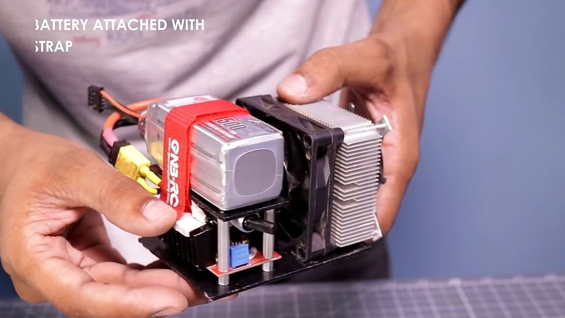
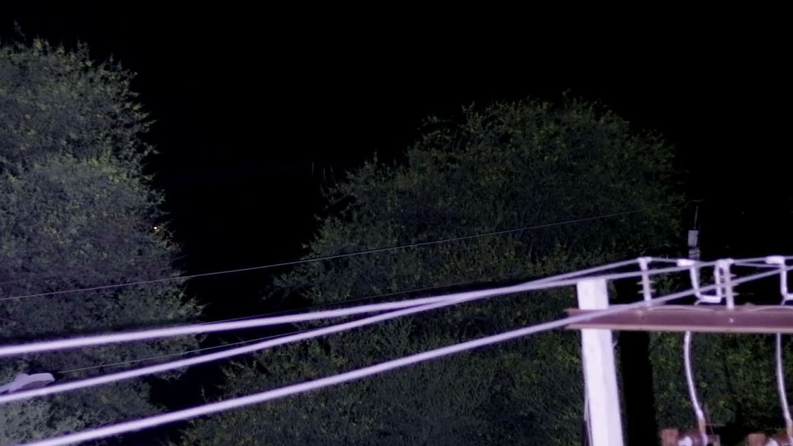
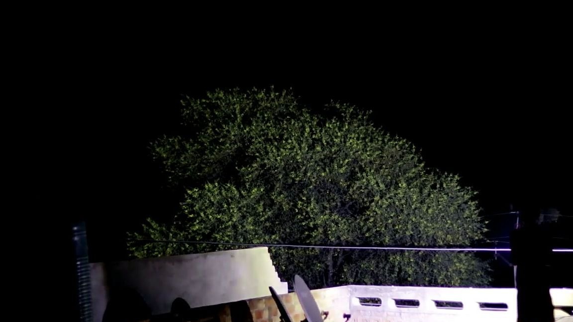
All is ready! It remains only to charge and install the battery in its place, namely on the platform to which the switch is glued. It is important to know that recharging a li-po battery is life threatening, as it can ignite, and it must not be recharged, it can also ignite it. Therefore, it is recommended to use "tweeters", which will warn about the discharge. And you should also use quality and proven chargers. As a result, we got an excellent test lamp, which you can see in the photo below. If you need a more focused beam of light then you can use a different kind of lens.


Here is a video from the author with a detailed assembly and testing of this homemade product:
Well, thank you all for your attention and good luck in future projects, friends!