

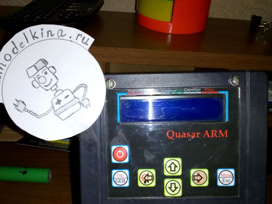
Quasar ARM - This is one of the most popular metal detectors, the circuit and firmware of which are in the public domain on the author’s site, for which special thanks to him. The capabilities of this device bring it to the same level with many commercial and expensive models. The author constantly improves his creation and from time to time releases new firmware, each of which gives the device new features, increases its stability and accuracy in determining the type of metal. In this article I will tell you how to update firmware metal detector on the example of your device.
So, if you are a happy owner Quasar ARM and want to refresh it with the new firmware, carefully read the instructions below.
As you know (or unknown), the microprocessor serves as the brain of the quasar STM32F100C. And no matter how we would like to minimize the complexity of its firmware, we still need a special USB-to-TTL programmer. Of course, you can assemble it yourself, but it is best to buy or borrow from a friend for temporary use. Such programmers are sold in radio stores. Personally, I took mine on Aliexpress. For specifics, I bring a photo No. 1 and No. 2, on which the desired programmer is shown on both sides.
As you know (or unknown), the microprocessor serves as the brain of the quasar STM32F100C. And no matter how we would like to minimize the complexity of its firmware, we still need a special USB-to-TTL programmer. Of course, you can assemble it yourself, but it is best to buy or borrow from a friend for temporary use. Such programmers are sold in radio stores. Personally, I took mine on Aliexpress. For specifics, I bring a photo No. 1 and No. 2, on which the desired programmer is shown on both sides.
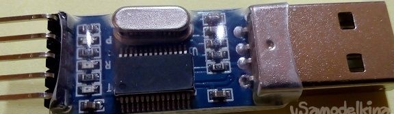
Photo No. 1 - programmer - top view
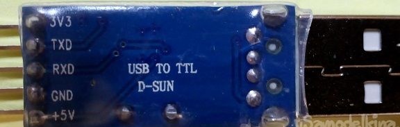
Photo No. 2 - programmer - bottom view
After the programmer is in your hands, you need to make friends with the operating system. I have installed on my computer Windows 10 and I admit, I had to break my head a bit in order to achieve a positive result in this direction. So, if you, too, have not accumulated on MAC and use the standard Windows, do the following: insert the programmer into any port USB computer and go to the task manager to see how it is determined in the system. Most likely you will get approximately the following picture (photo No. 3).
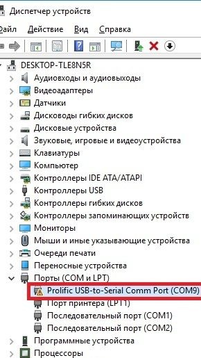
Photo No. 3 - a problem in determining the programmer
From the above photo it can be seen that Windows identified the programmer and assigned it a virtual port COM9. However, a small exclamation mark next to the name of the device indicates a problem with the driver and, as a result, the current inoperability of the programmer. This can be fixed by installing a special driver, which I managed to find on the Internet far from the first time. So, download the driver from this link:
Next, unpack the archive and get several files, as in photo No. 4.
Next, unpack the archive and get several files, as in photo No. 4.
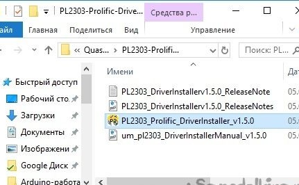
Photo No. 4 - unpacked archive with drivers for the programmer
Run the executable file from the archive and wait for the end of the installation. After which, we return to "device Manager", find the line with the name of the programmer (Photo No. 3), move the mouse cursor over it, press the right button and select"Update driver". The system will offer to install the driver automatically, or from a specified location on the computer - we are inclined to the second option, not forgetting to specify the folder with the unpacked archive, as in photo No. 5.
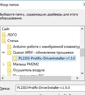
Photo No. 5 - selecting a folder with drivers
Most likely, after clicking the "OK", you will be asked to install one of the 2 drivers to choose from. You must select the one with the older version, as shown in photo number 6.
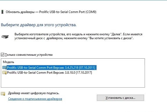
Photo No. 6 - installing an earlier version of the driver
Click "Further"and wait for the end of the process. Now the programmer should be correctly detected in the system. To check this fact, reopen"device Manager"and pay attention to the line where there was an exclamation mark. If everything went well, it should disappear, as shown in photo No. 7.
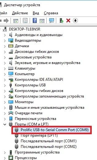
Photo No. 7 - the correct definition of the programmer (no exclamation mark)
So, the programmer is installed, it remains to configure it correctly. Right-click on the name of the programmer in "Device manager"(photo No. 7), in the drop-down menu, select"The properties"and in the window that opens, go to the tab"Port settings". Here you can configure the port speed and the algorithm for communicating with the program through which we will flash our processor in the future. Set the values in accordance with photo No. 8 below.
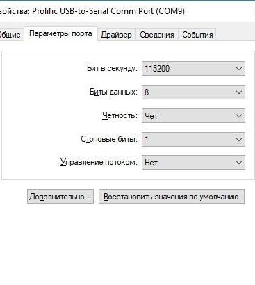
Photo No. 8 - correct programmer port settings
From this moment the first and most unpleasant stage is completed. The only plus is that it needs to be done once. With subsequent firmware, programming is not required. Now let's decide on how to connect the programmer to your metal detector. In most cases, special pins for connecting the programmer are divorced and signed on the printed circuit boards. In my case, the pins were soldered, but not signed. It looked something like this (photo 9).
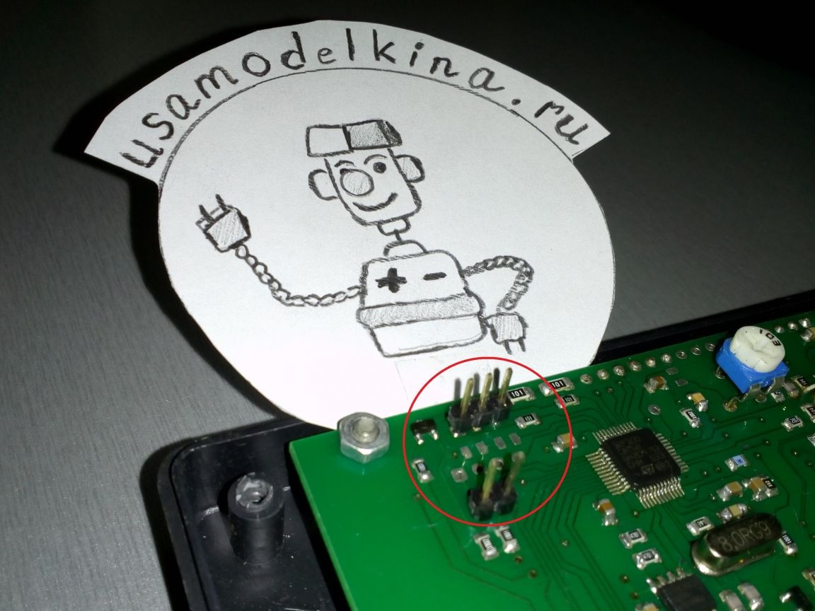
Photo No. 9 - an unnamed programming socket
If you have a similar situation, then you should pick up a tester and call everything according to the diagram below (photo No. 10).
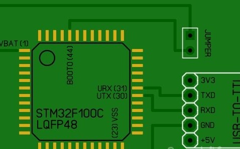
Photo No. 10 - connection diagram of the programmer
In this diagram, I depicted a way to connect the programmer to a microprocessor, regardless of the type of circuit board on which your Quasar ARM. This is the classic way to program UART interface. A little explanation on the scheme. IN 99% you will have a microprocessor in the case LQFP48. The numbering of his contacts begins with a small round icon and goes counterclockwise. For clarity, all necessary contacts are signed on the diagram with their numbers in brackets. Pins Rx, TX and Vss microprocessors are connected directly to the programmer. Conclusion BOOT0, serves to translate STM32 to programming mode. To enter this mode, you must close BOOT0 with power output Vbatotherwise, the processor will simply start and will work as usual. Later I will give a specific sequence of actions so that you do not have confusion in your head.
We figured out the connection - you can download software for programming. Microprocessors STM32 programmed using a special proprietary program Flash loader demonstrator. It is free and is on company official website. Installation should not cause difficulties, so I will leave this point unattended. Next we go to author website and download the latest firmware. At the time of this writing, the latest version 2.3.3, as evidenced by photo No. 11 but I prefer a more stable version 2.2.18.
We figured out the connection - you can download software for programming. Microprocessors STM32 programmed using a special proprietary program Flash loader demonstrator. It is free and is on company official website. Installation should not cause difficulties, so I will leave this point unattended. Next we go to author website and download the latest firmware. At the time of this writing, the latest version 2.3.3, as evidenced by photo No. 11 but I prefer a more stable version 2.2.18.
Photo No. 11 - the firmware that I selected for recording in MD
The downloaded archive must be unpacked and a file with the extension .hex. This is the binary firmware file. Now we can proceed to the final and most crucial stage.
First of all, we connect the programmer and close the output using the jumper BOOT0 and Vbat microprocessor. We insert the programmer into the port USB and apply power to the metal detector. If there is nothing on the screen, then we are on the right track and the microprocessor has switched to programming mode. At the moment, you should have approximately the same picture as in photo No. 12
First of all, we connect the programmer and close the output using the jumper BOOT0 and Vbat microprocessor. We insert the programmer into the port USB and apply power to the metal detector. If there is nothing on the screen, then we are on the right track and the microprocessor has switched to programming mode. At the moment, you should have approximately the same picture as in photo No. 12
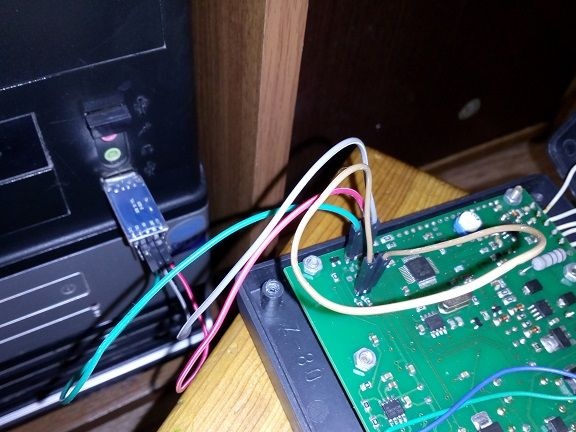
Photo No. 12 - the jumper is closed, the programmer is connected, power is supplied
Next, run Flash loader demonstrator. The window shown in photo No. 13 should appear in front of you.
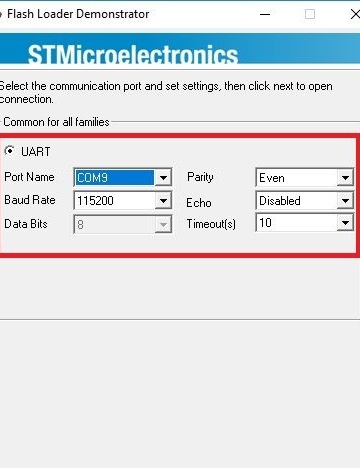
Photo 13 - connection settings
These are the connection settings for UART protocol. The indicated numbers must exactly correspond to what we set in the programmer port settings window (photo No. 8). Parameter Port name - the name of the virtual port that it assigned Windows to the programmer. It will probably be different for you. This name can be spied in "Device manager"on the example of photo No. 7. When all the settings are set - click"Next"to go to the next stage (photo 14)
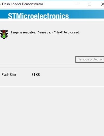
Photo No. 14 - the program saw a microprocessor
As can be seen from the above photo, the program determined the processor and the size of its flash-memory (64 KB). This suggests that we are on the right track and you can go further - click "Next", after which we see the next window (photo No. 15).
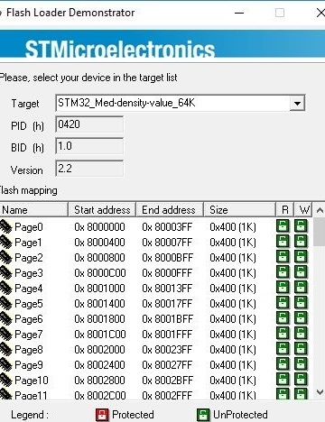
Photo No. 15 - microprocessor memory card
This window is not valuable to us and simply displays the internal structure of memory. STM32. Click "Next"to go to the next item (photo 16)
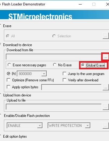
Photo No. 16 - final settings
In this window, check the box Glabal eraseso that all unnecessary garbage is removed from the microprocessor before programming. Next, click on the button with three dots to add the firmware file, after which the dialog box shown in photo No. 17 opens.
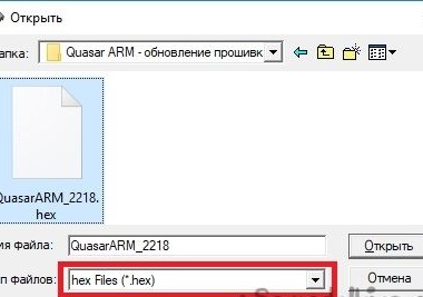
Photo No. 17 - adding a firmware file
Here you need to go to the folder where the firmware was downloaded and unpacked from the author’s site. Note that the file was visible, you must set the file type * .hex (initially there will be a different value). Open the specified file and sew the microprocessor. This process is shown in photo No. 18.
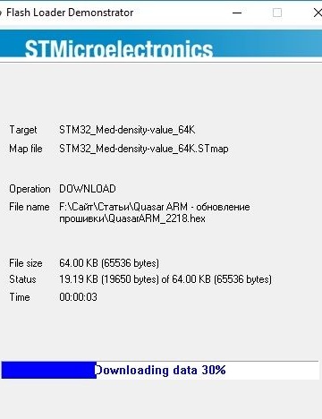
Photo No. 18 - firmware process
In general, recording a program takes a few seconds, after which we receive a message about the successful completion of affairs (photo No. 19).
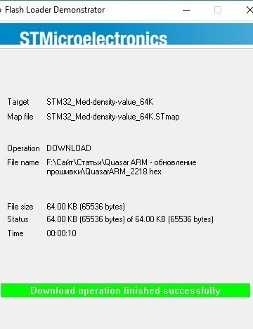
Photo # 19 - firmware completed successfully
Now you can close the program, disassemble the circuit (do not forget to remove the jumper from BOOT0) and perform a test run. Photo No. 20 shows the result of my efforts before and after updating the firmware.
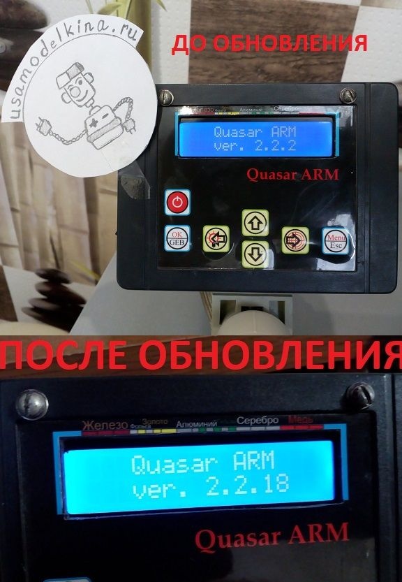
Photo №20 - the final result
I hope I managed to express my thoughts in an accessible language and this material will help the residents of our sites to update their devices without unnecessary gestures. All creative success !!!