
This article will be of interest to everyone who works with heavy metal products, such as sheet metal, steel channels and beams. The author of the channel "Make it Extreme" made a powerful electromagnet for lifting and moving ferrous metal products.
And for this, from the materials he needed:
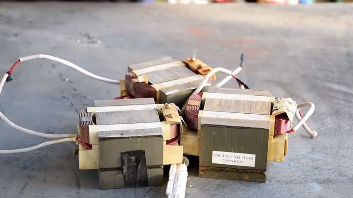
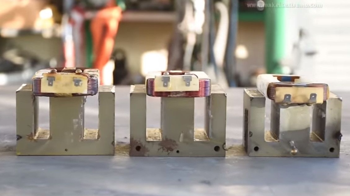
1. Three transformers from the microwave
2. Steel sheet
3. Steel strip
4. Epoxy
5. A few wires and terminals
6. Eye bolt with nut M12
7. Power supply 24 V 100 watts, preferably redundant battery.
Instruments.
1. Welding machine
2. Bending machine
3. Drill or drilling machine
4. Milling machine
5. Power saw.
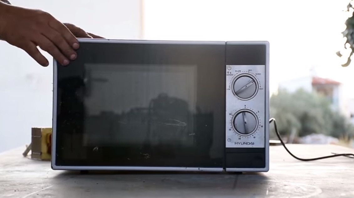
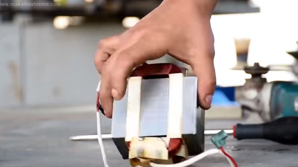
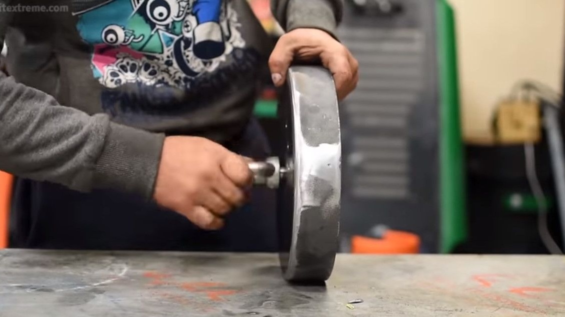
So, as usual, in order to do something, you need to break something. The author approached several old microwave ovens. Not in a very barbaric way, but takes them apart for parts.
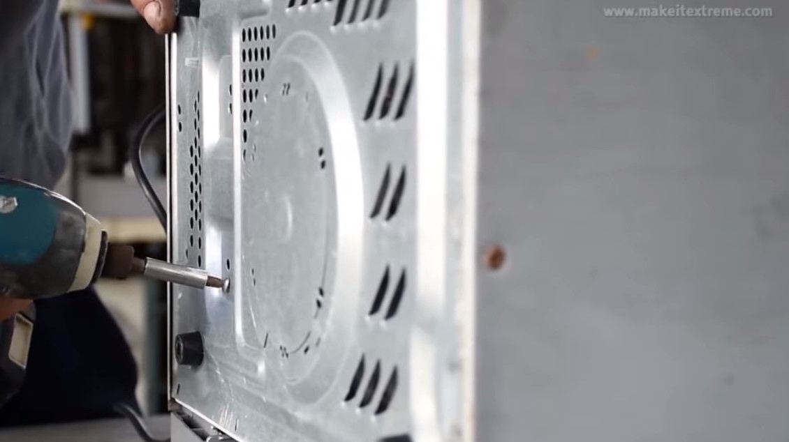
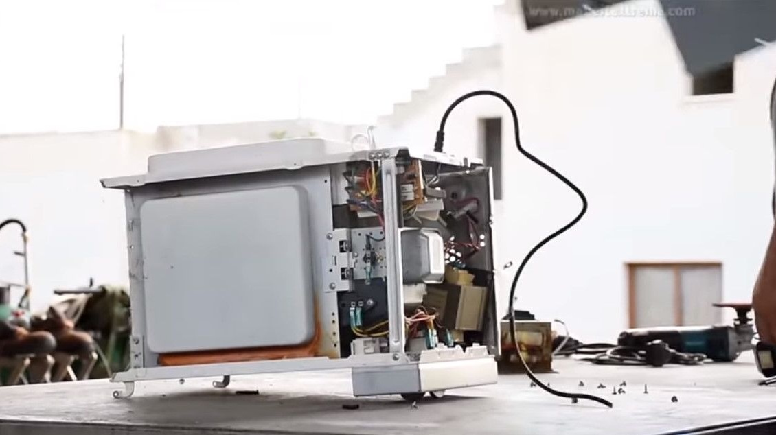
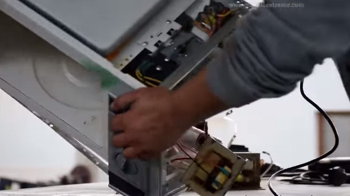
It extracts the most valuable and necessary for this homemade product - a transformer.
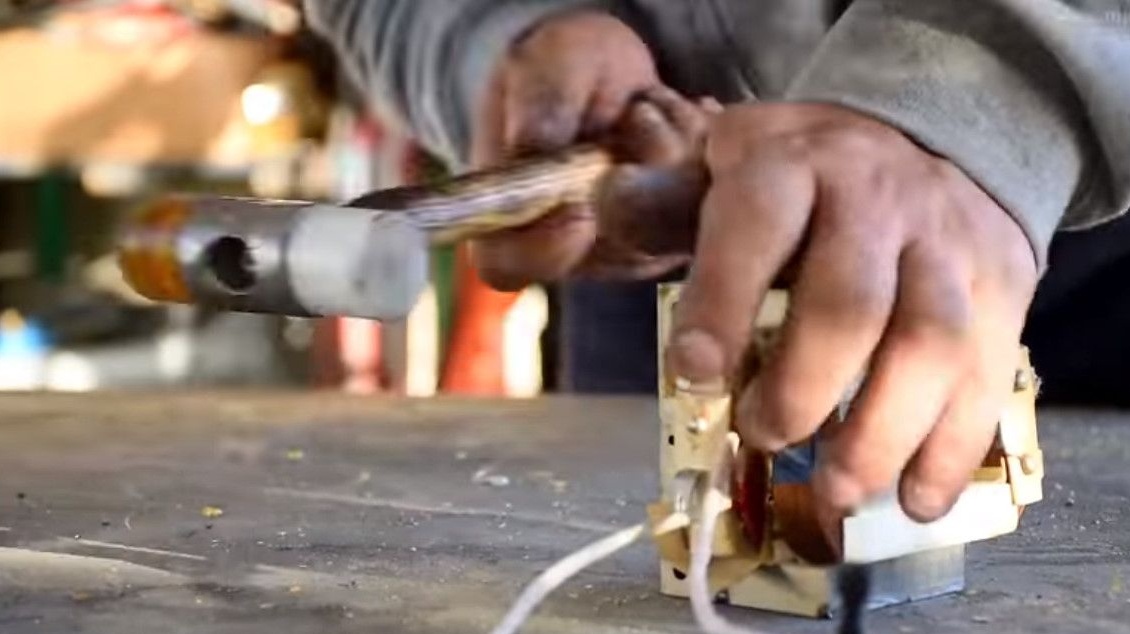
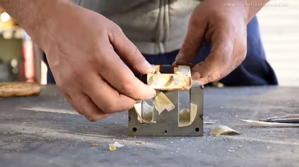
With the help of a grinder and a screwdriver, it separates the sole, this must be done carefully so as not to damage the winding.
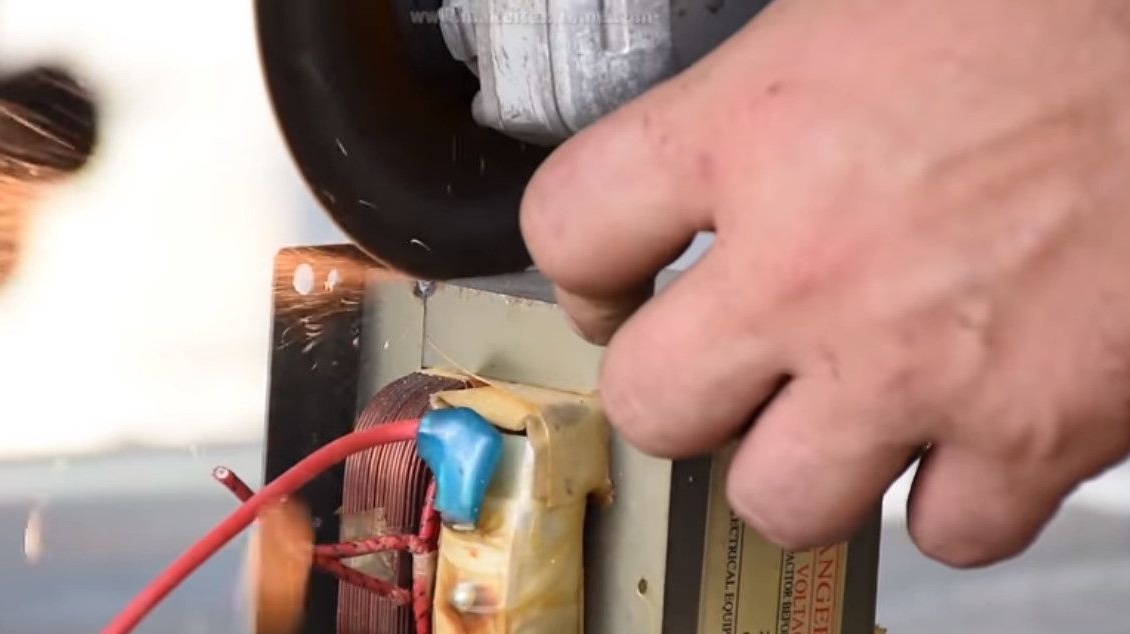
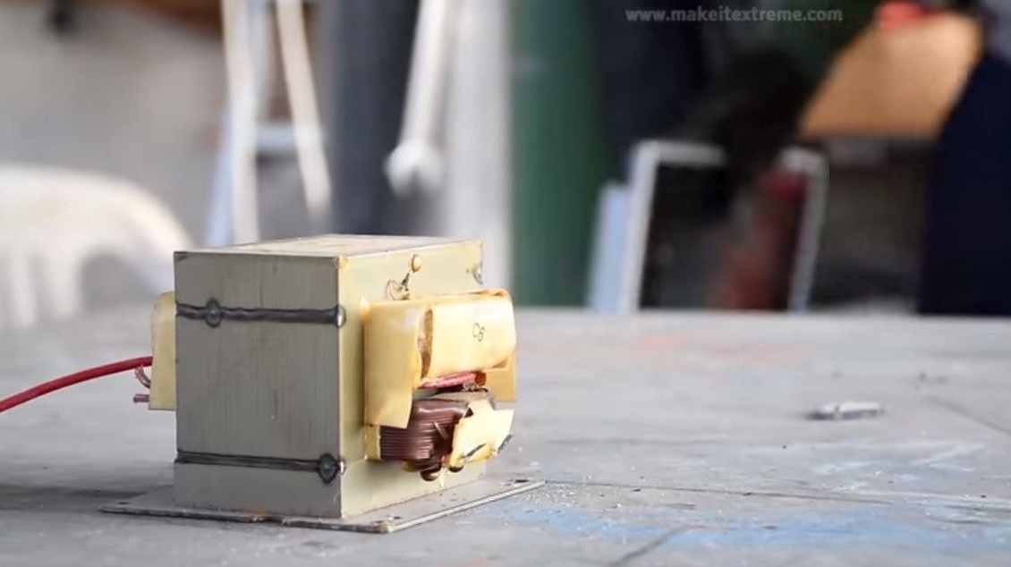
It should be like this.
Knocks out a winding with a hammer.
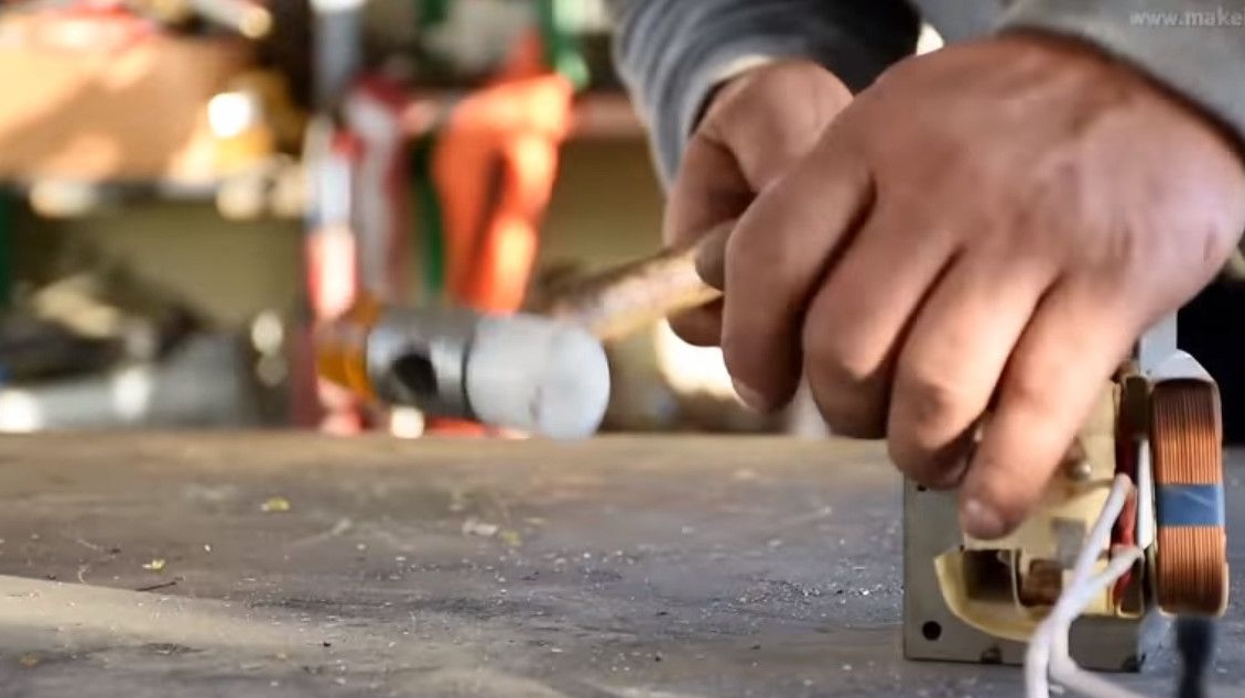
He takes out the most necessary - the primary.
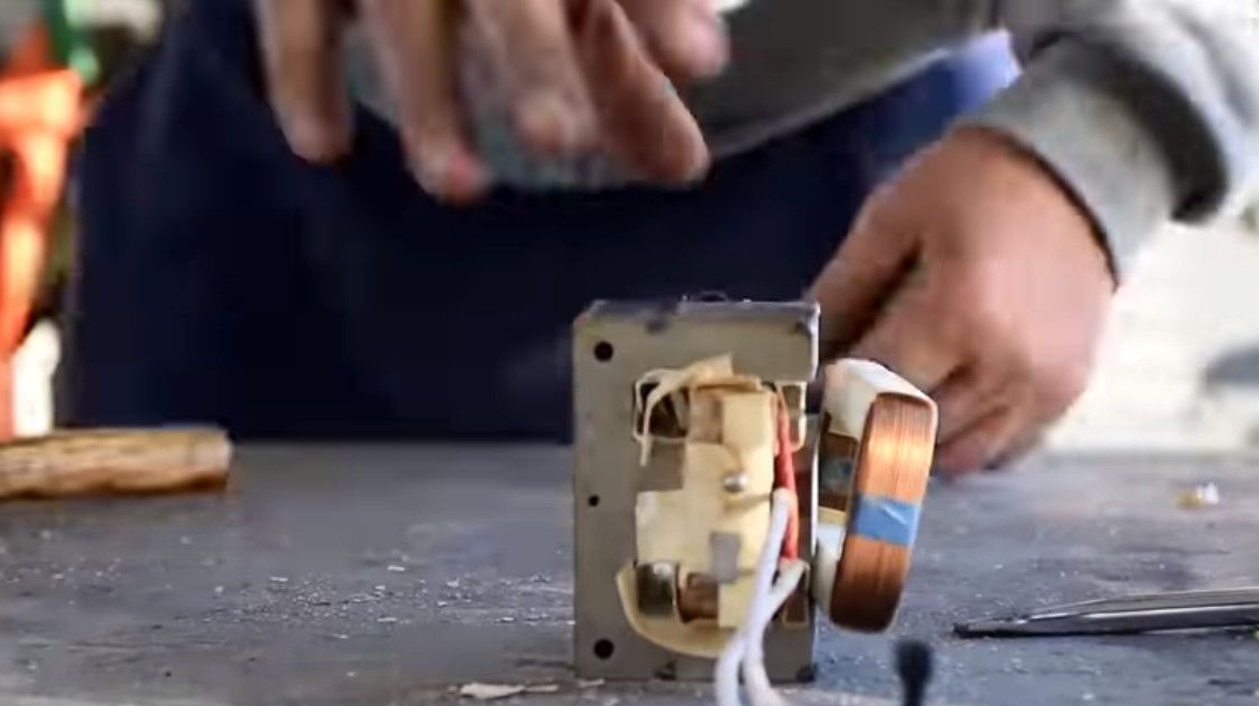
And removes the secondary.
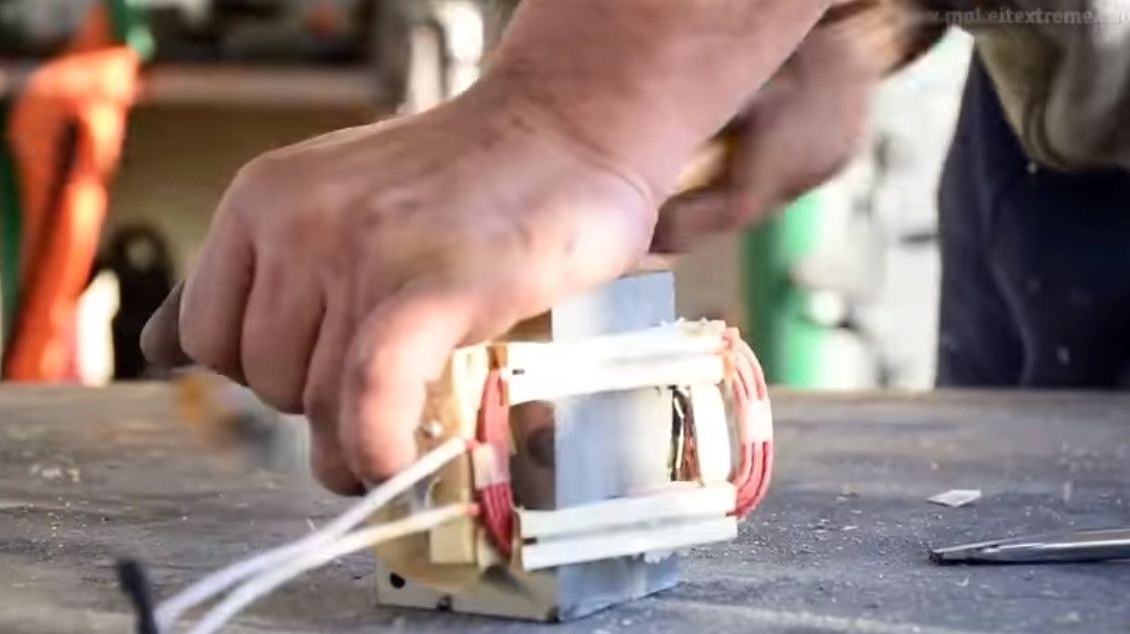
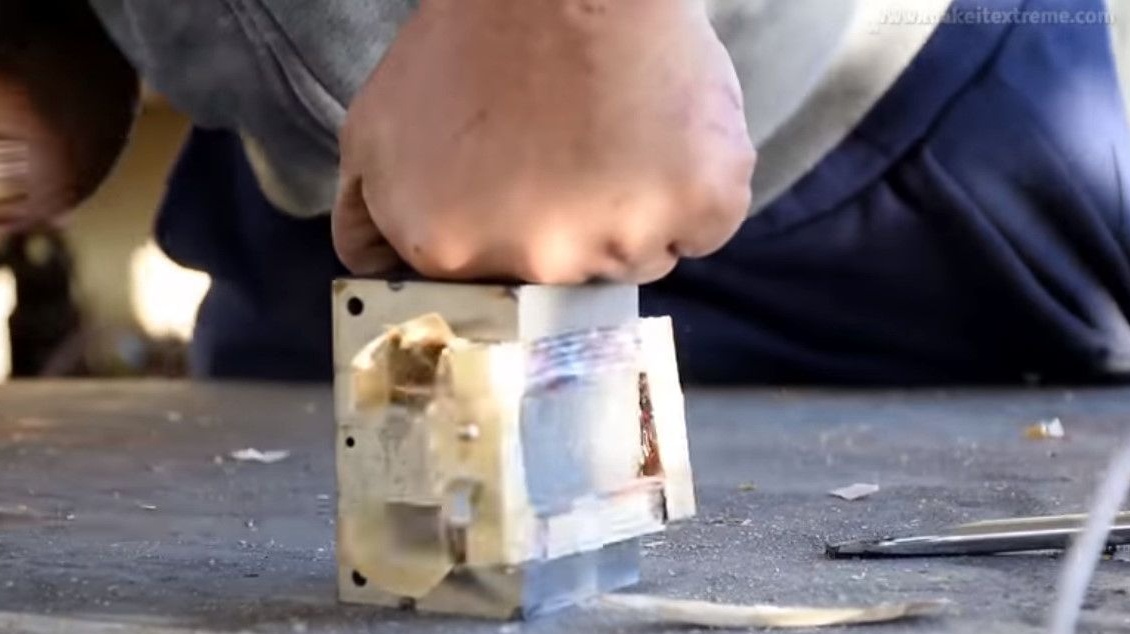
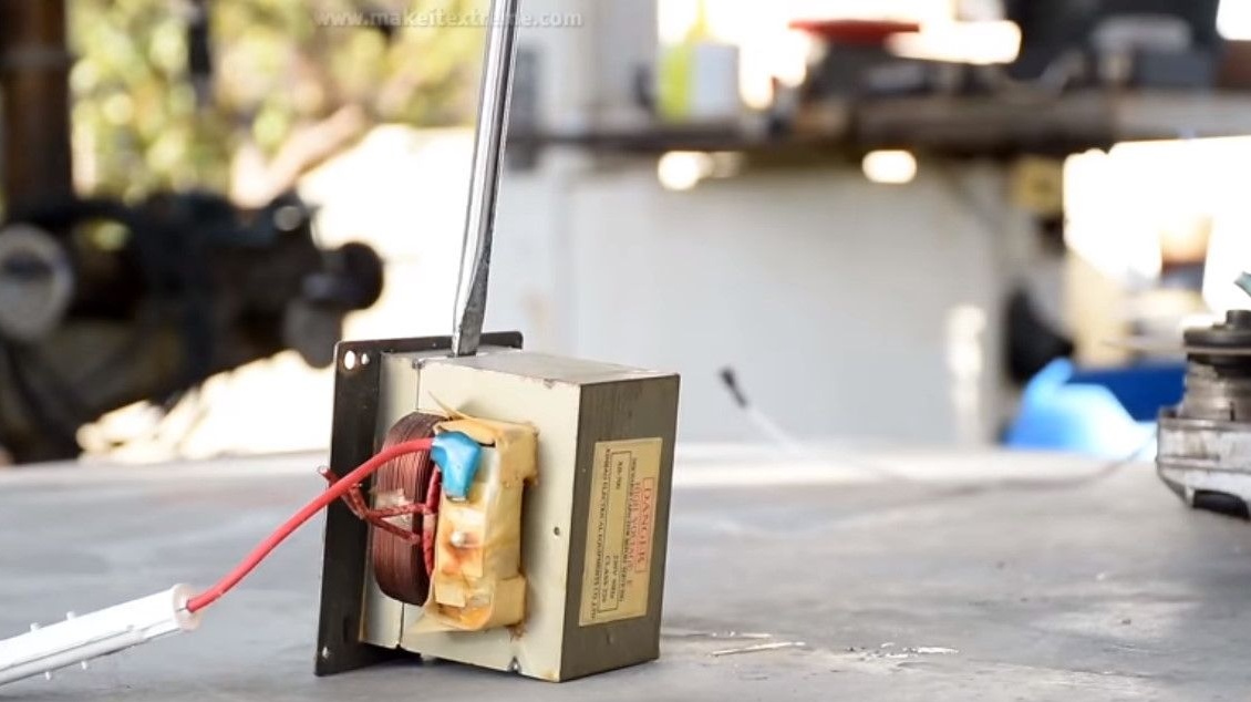
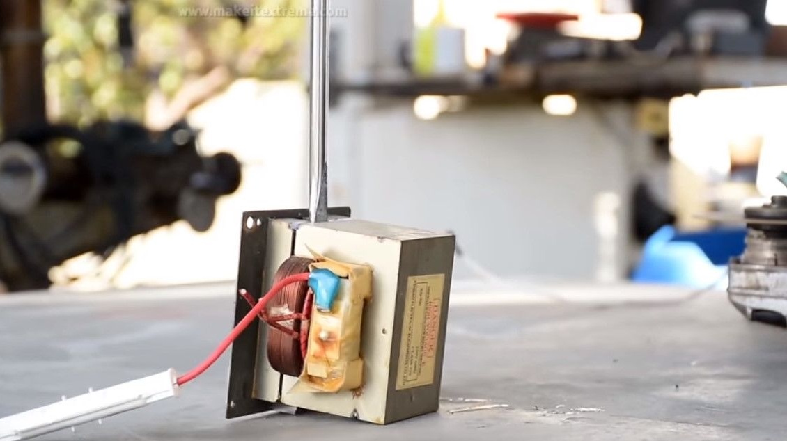
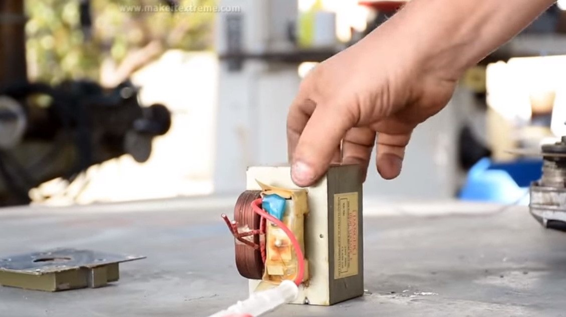
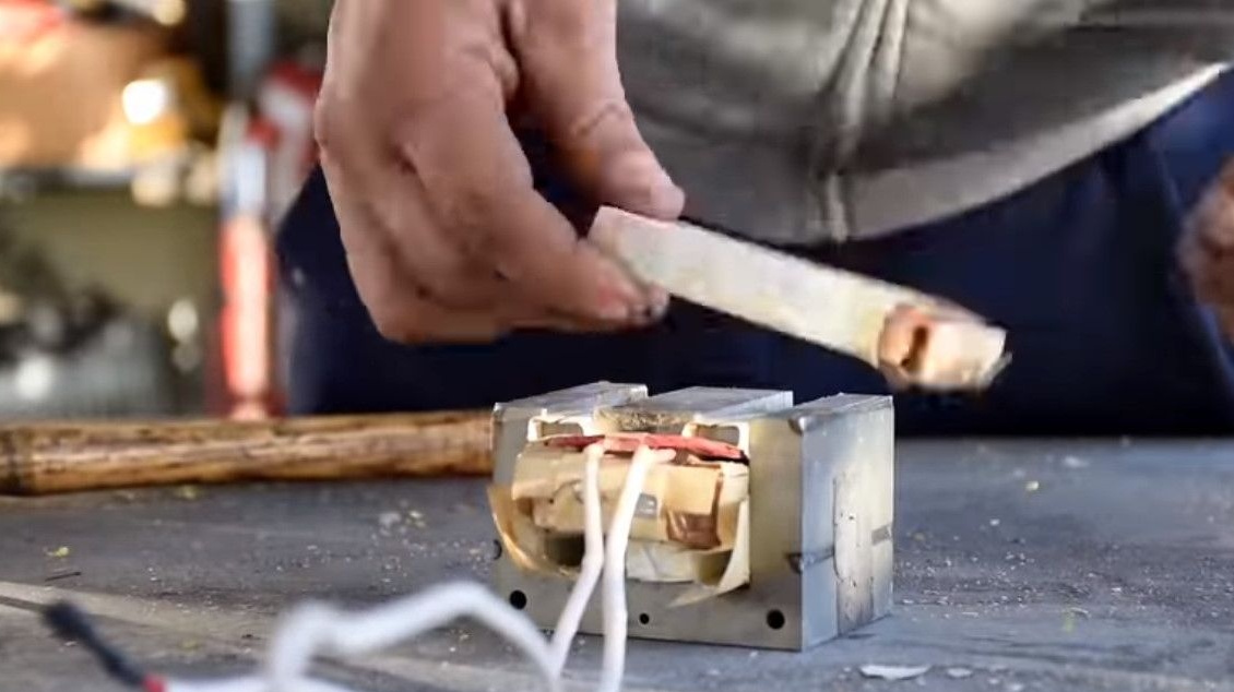
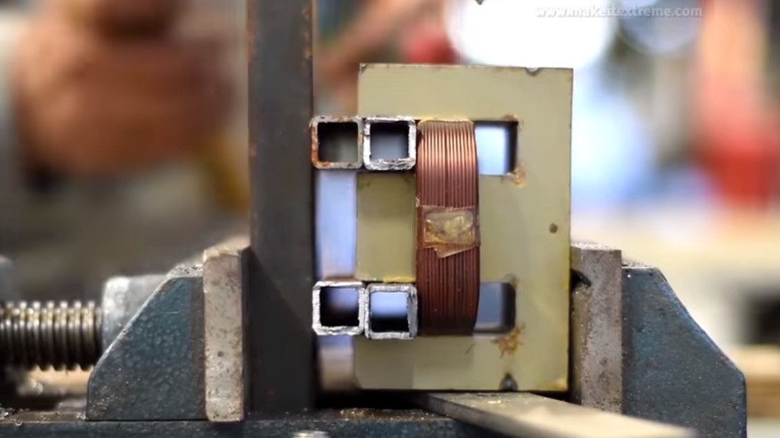
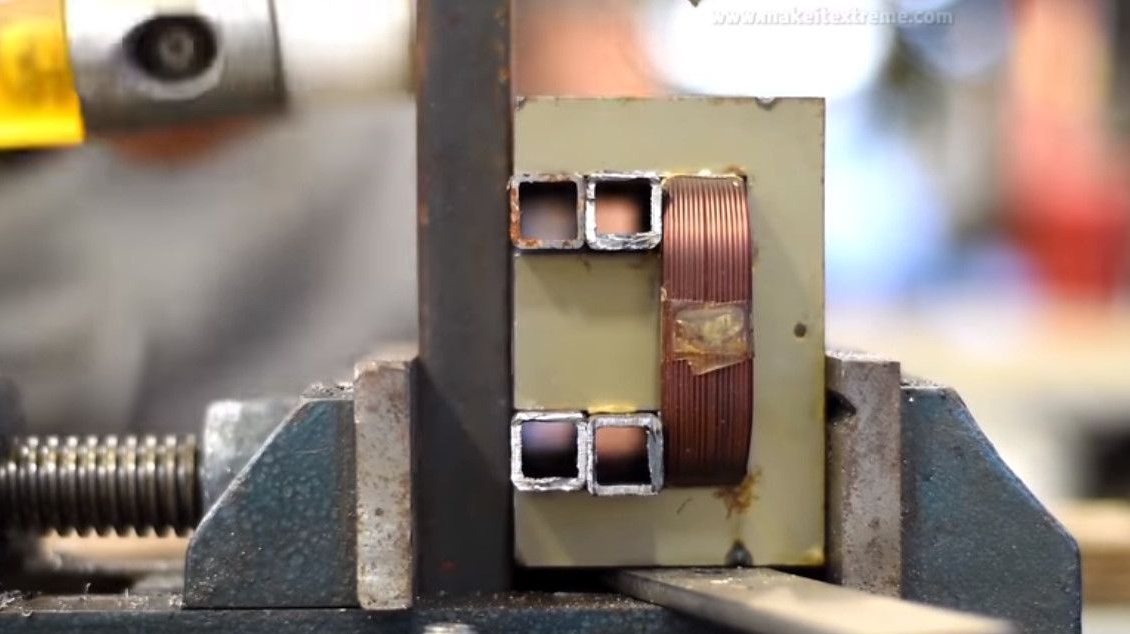
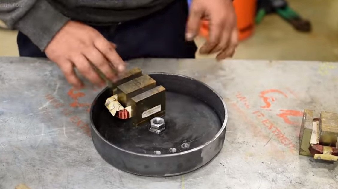
Now the primary winding needs to be installed on the remaining W-shaped core.
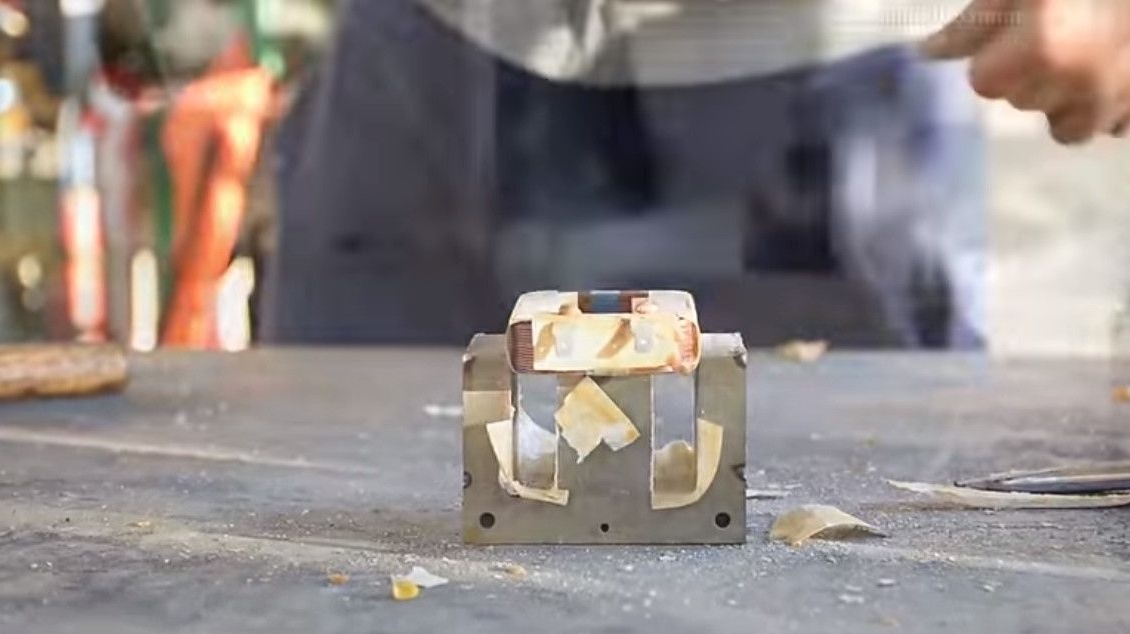
To do this, the author uses a vise, inserting a square profile pipe between the winding and the vise, presses in the primary.
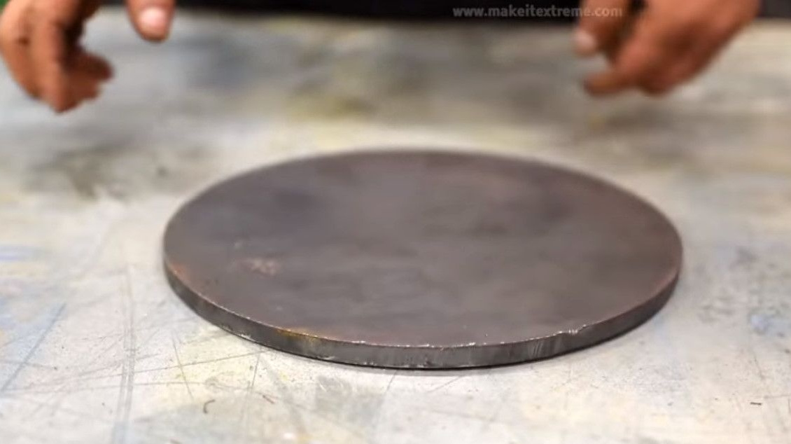
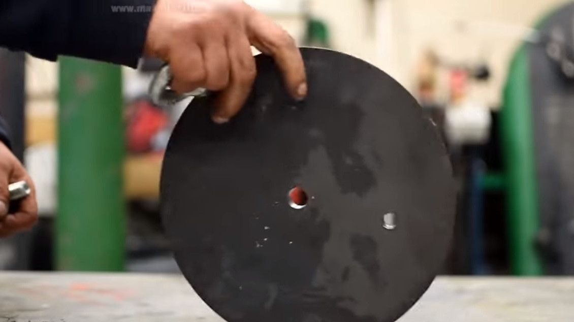
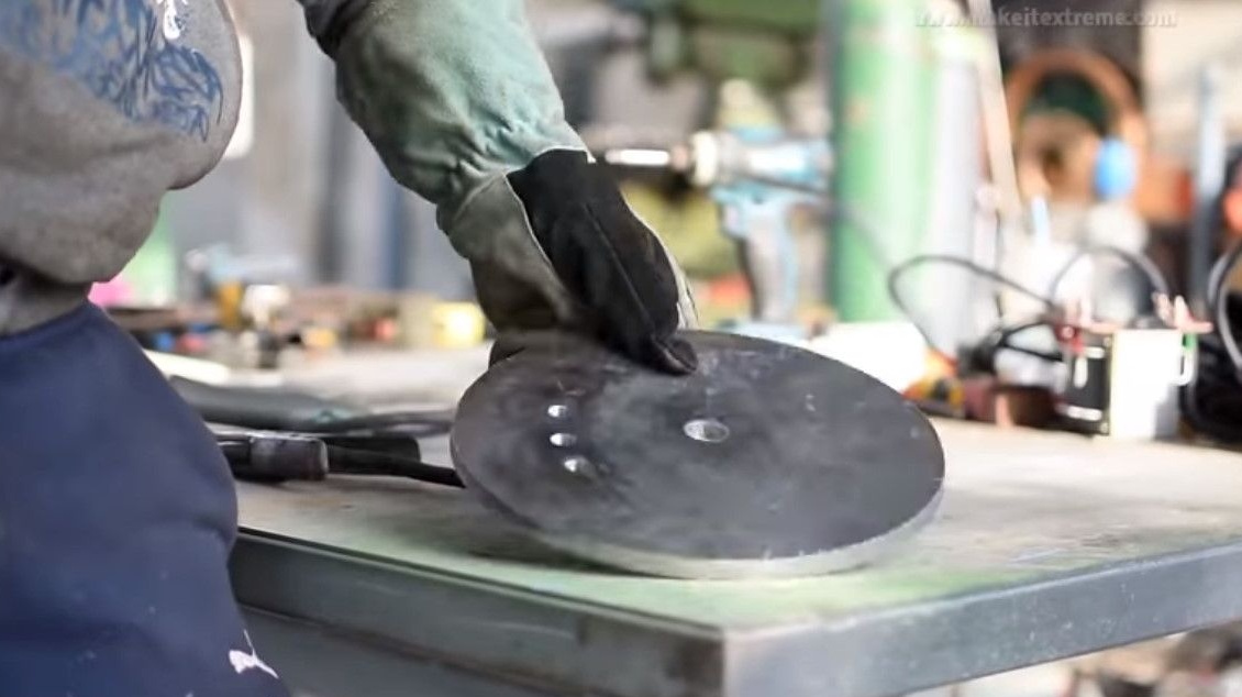
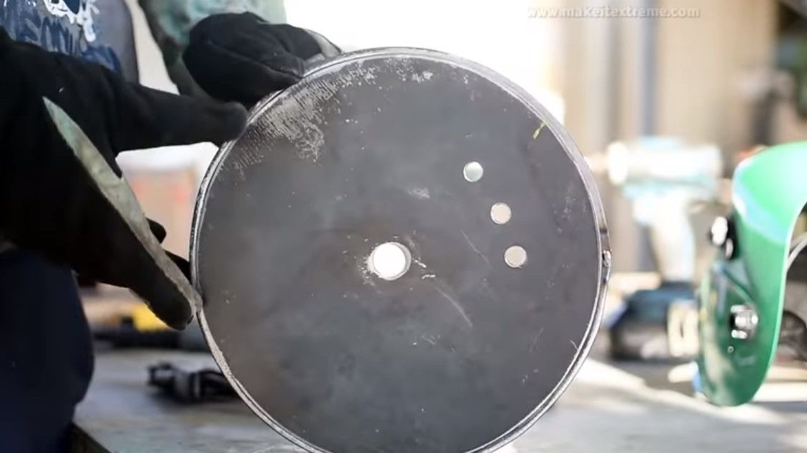
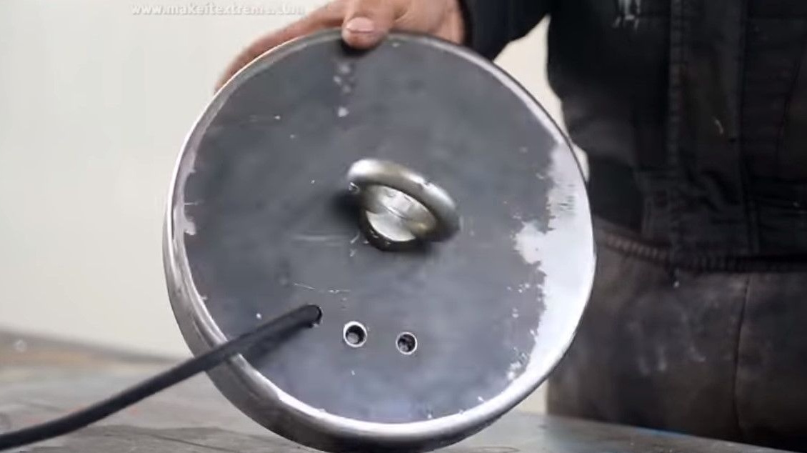
Now you need a base, in the end it will become a cover.
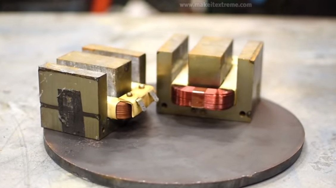
Approximately selects the location of the transformers.
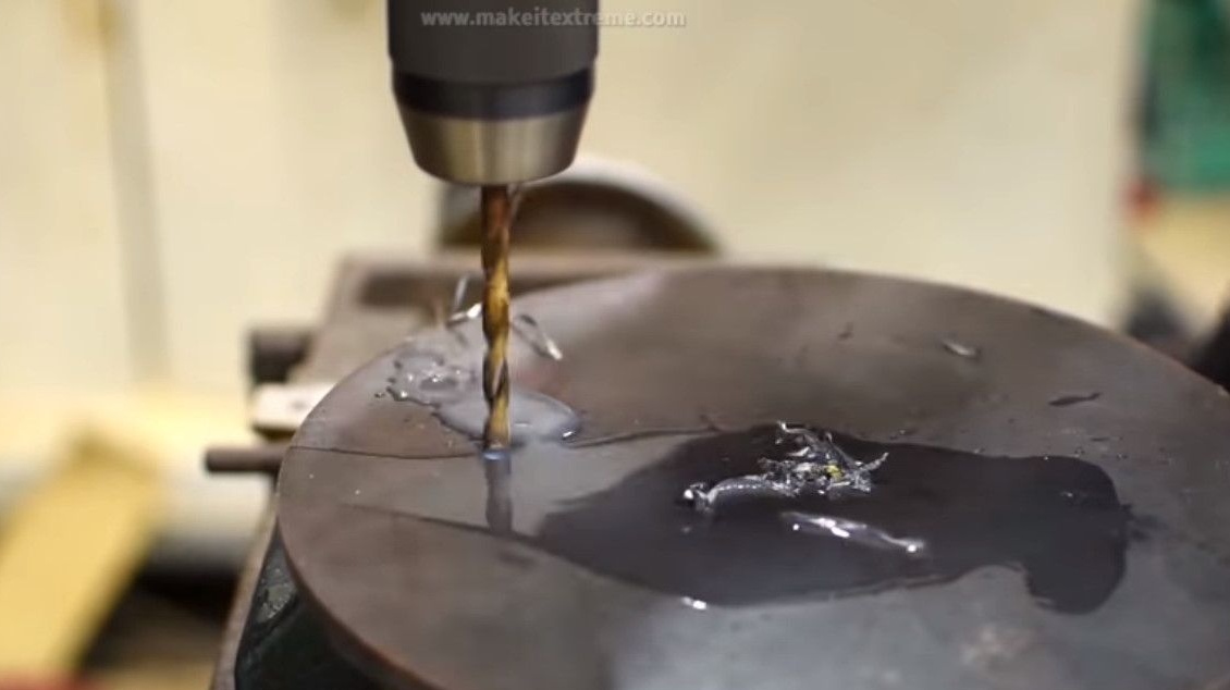
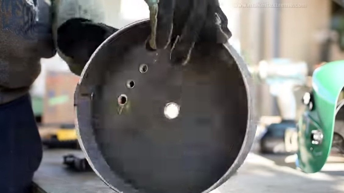
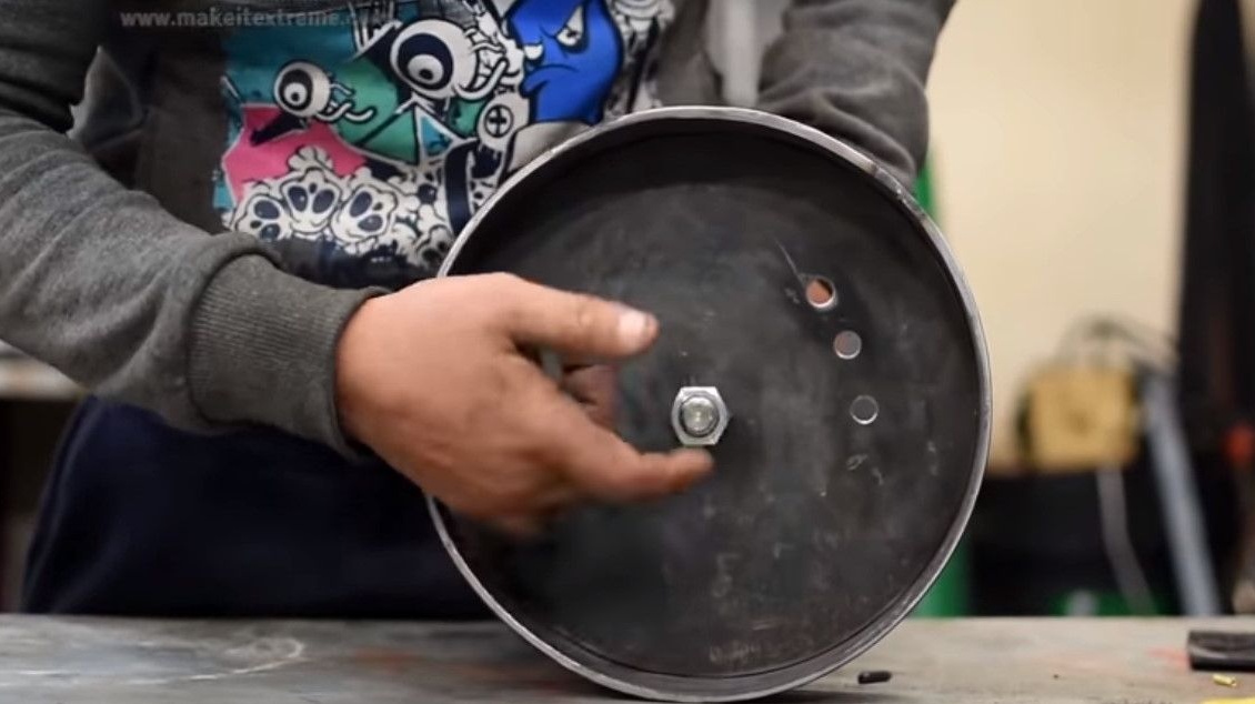
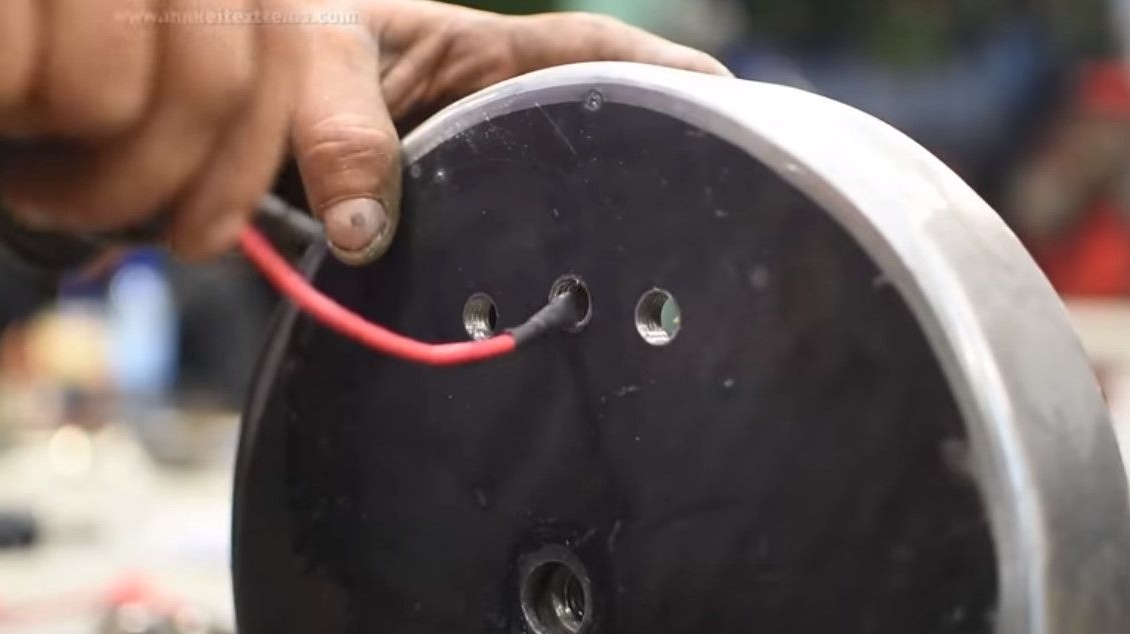
And he drills the holes for the wire and the eye bolt at the base. It starts with a small diameter drill, and ends with the 12th.


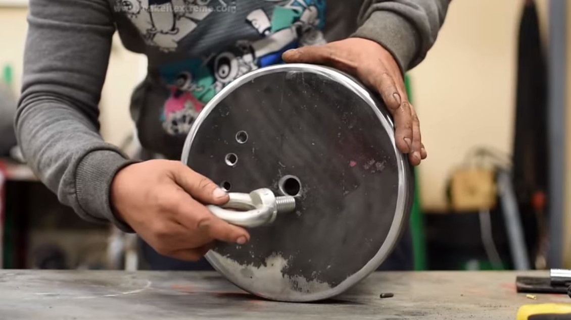
That’s the basis.
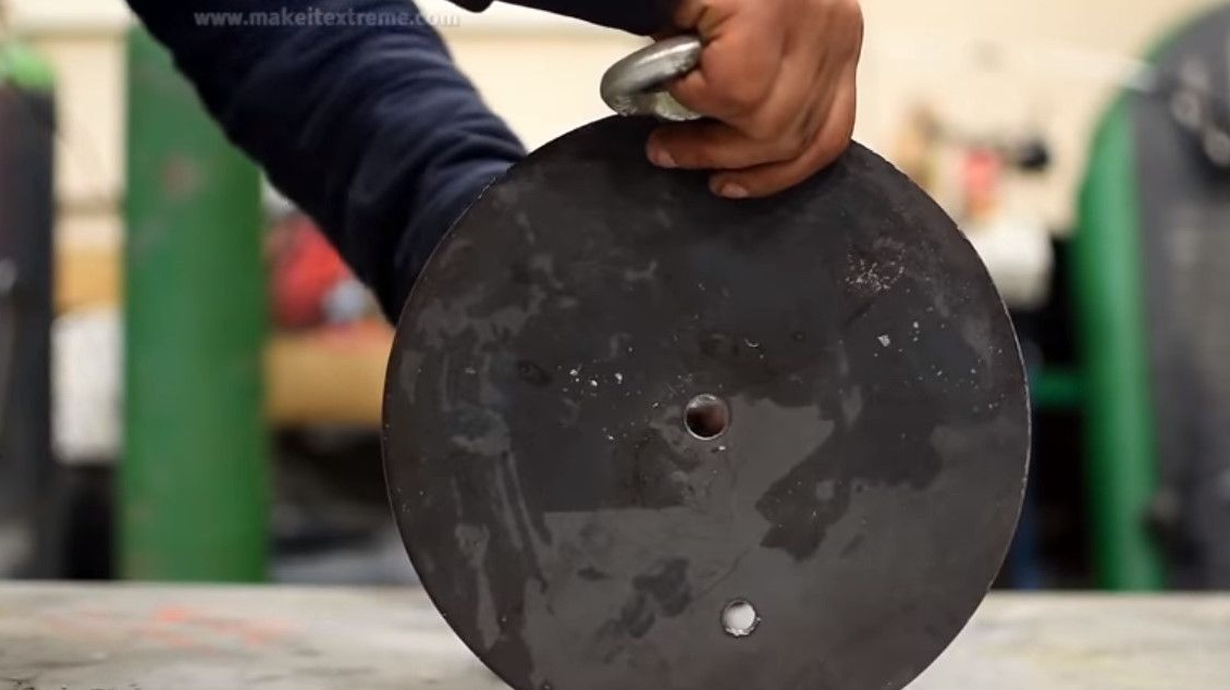
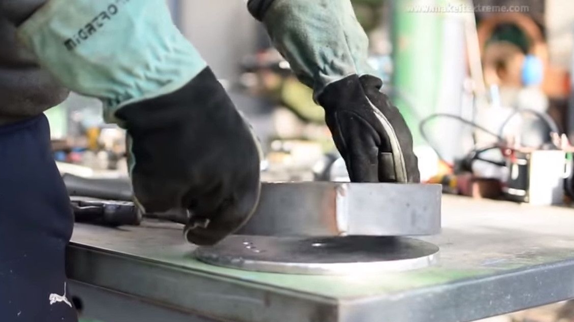
Inserts an eye bolt and tightens the nut.
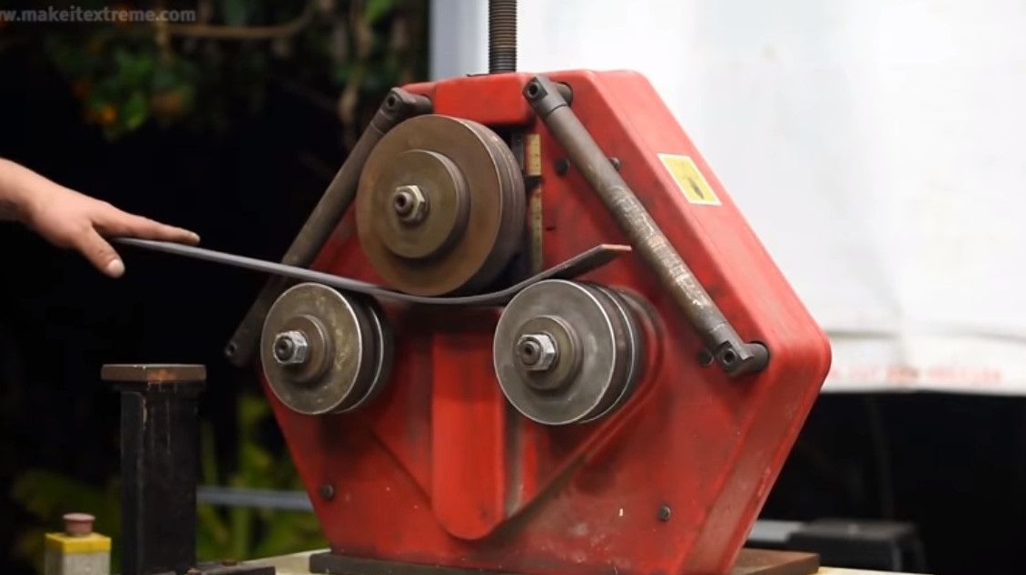
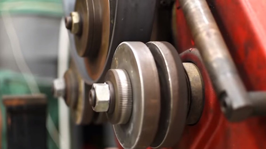
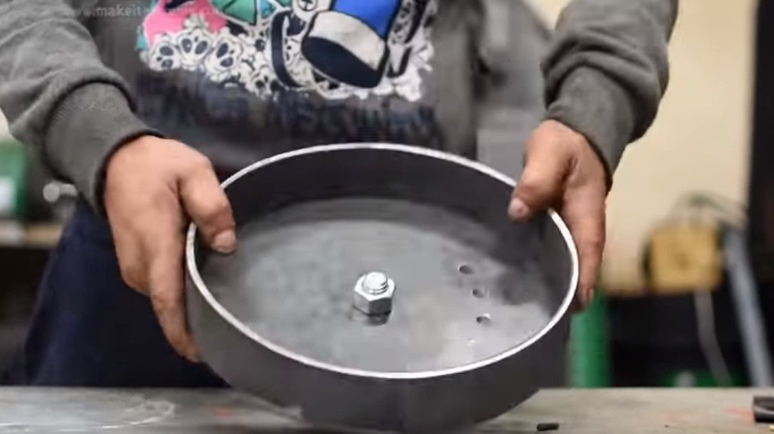
On a bending machine makes a "skirt" or rim from a steel strip.
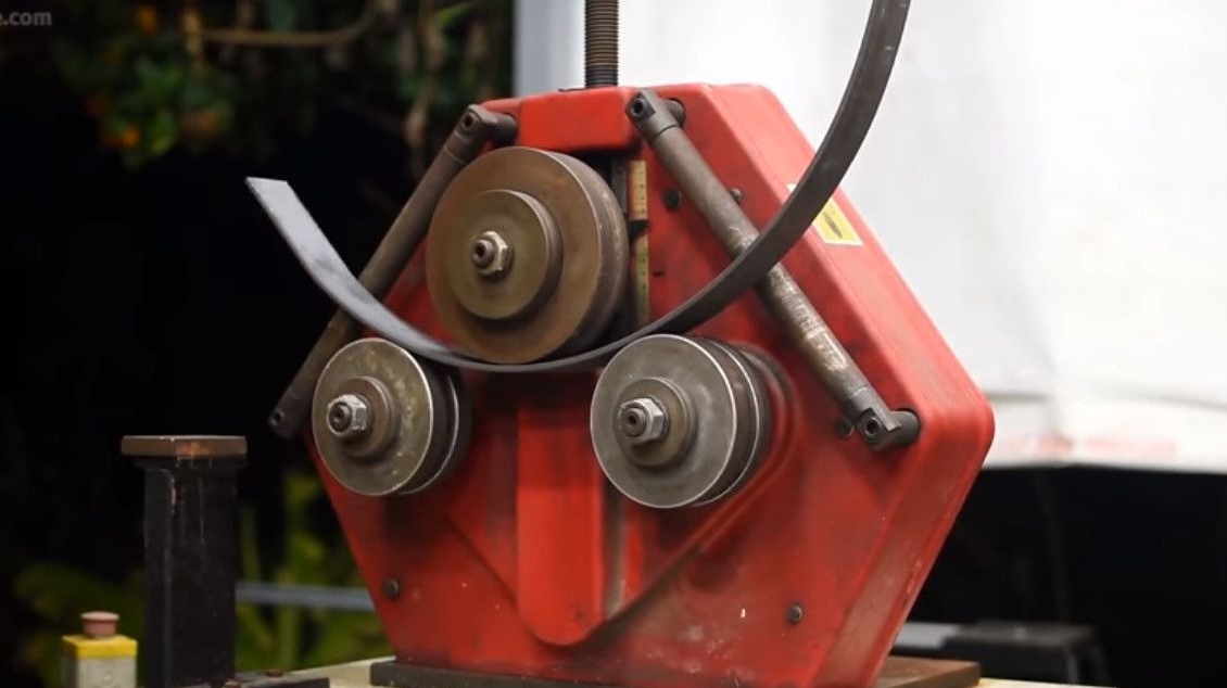
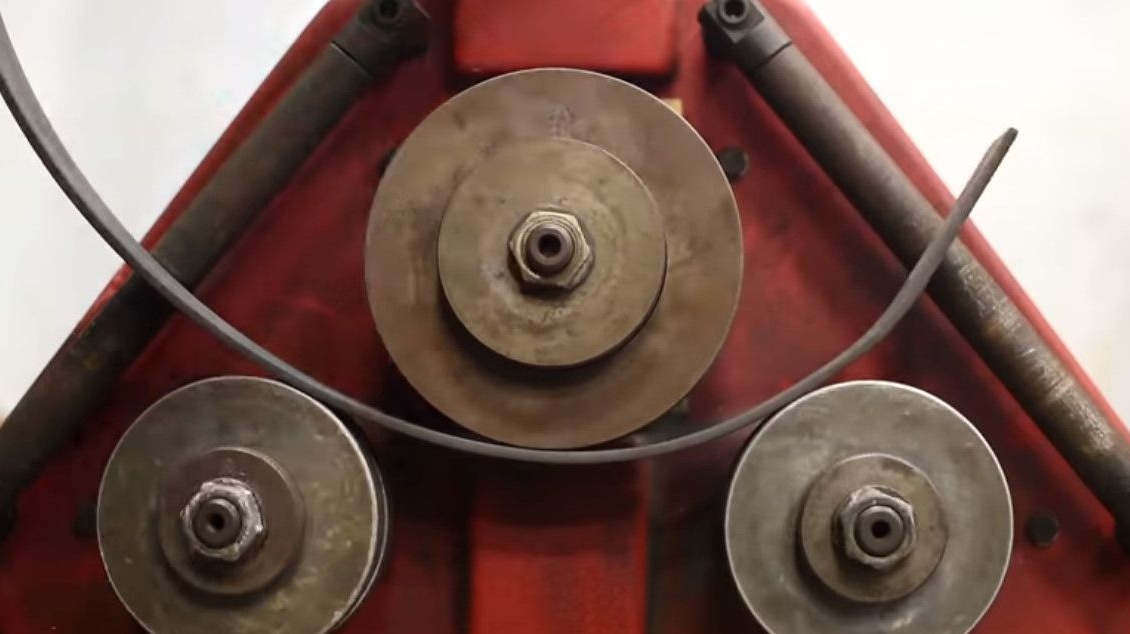
It turns out this kind of blank.


Boil the rim joint.
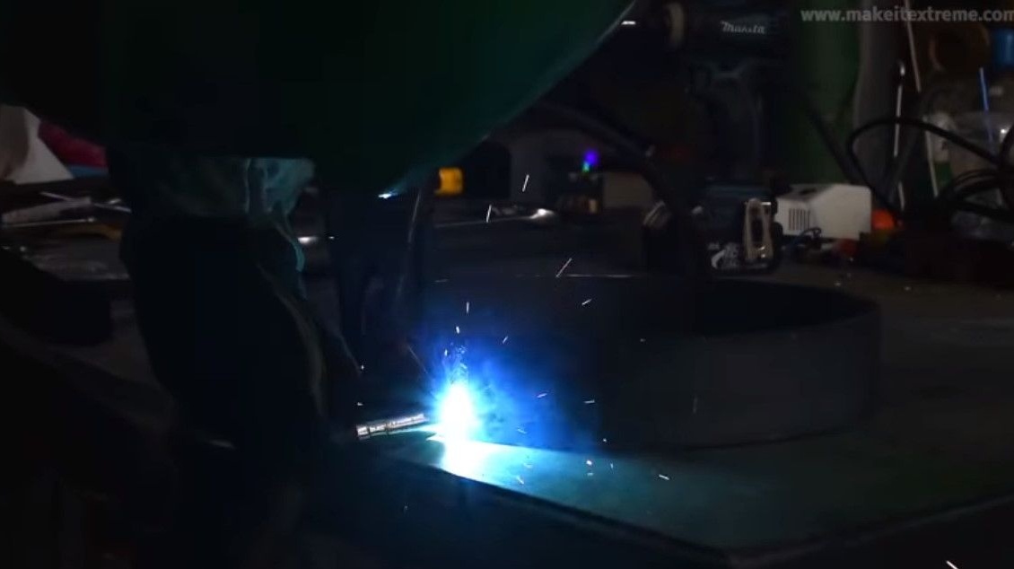
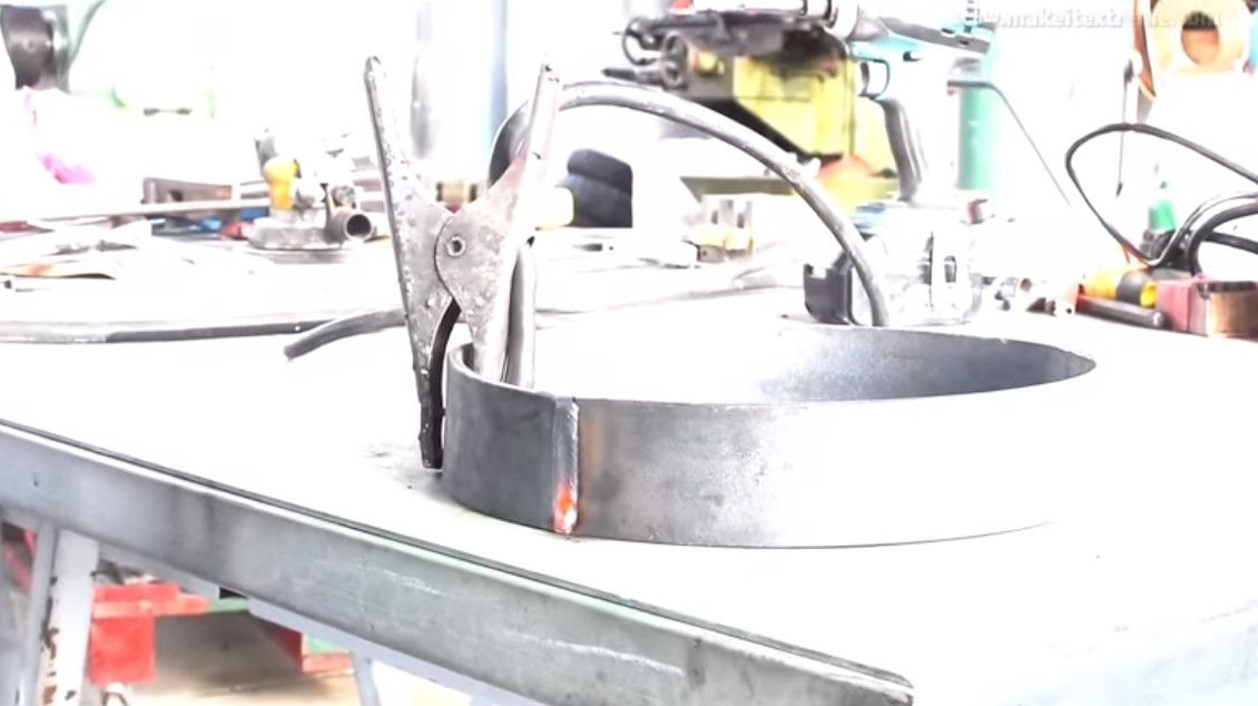
Assembles a casing together.
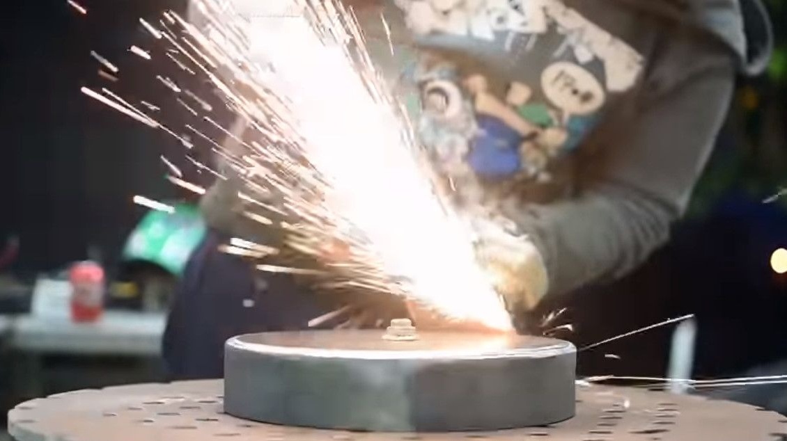
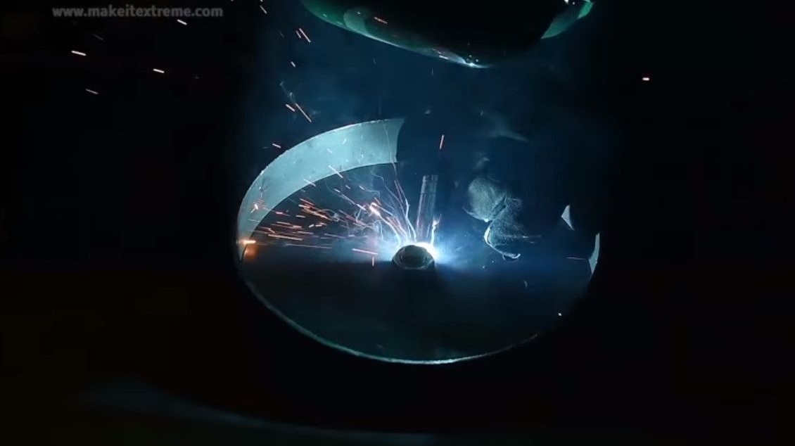
Boils a seam between the base and the rim.
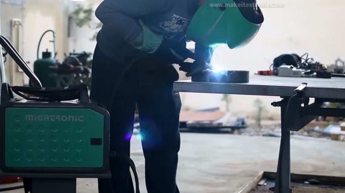


Here's a seam from the author.
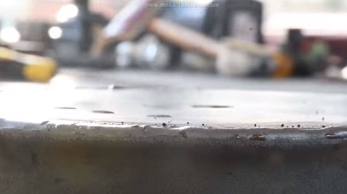
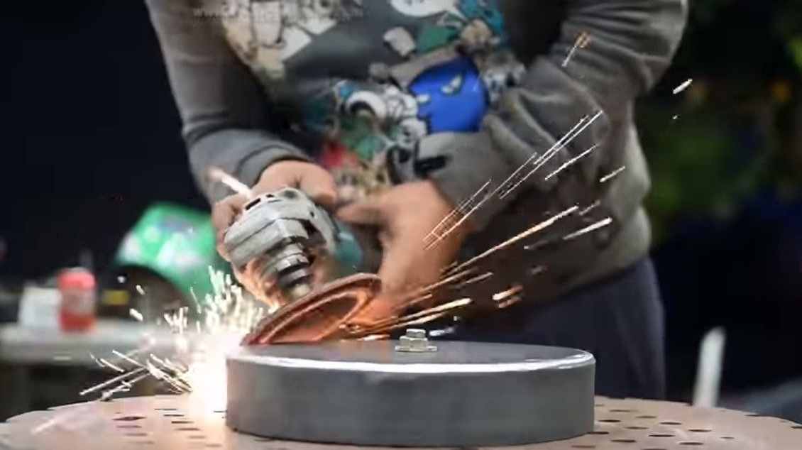
Cleans the seam and surface with a grinder.
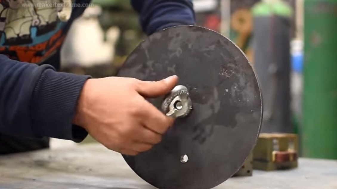
Inserts an eye bolt and tightens the nut. Yes, the puck is not needed here, the effort will be directed towards the base.
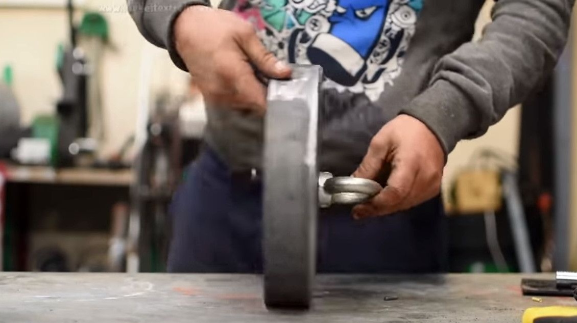
Welds the nut to the base.
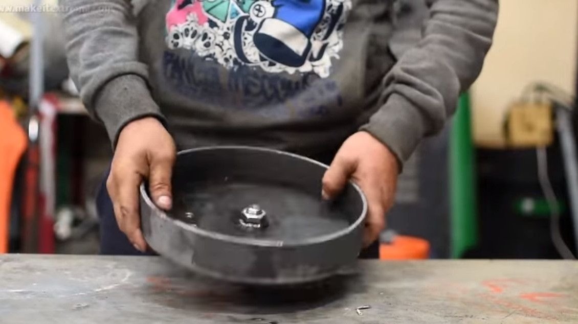
The bolt unscrews the eye, it will interfere with further assembly.
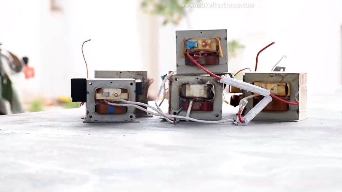
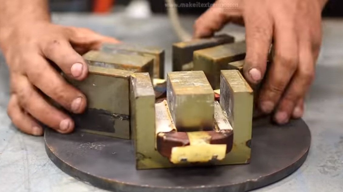
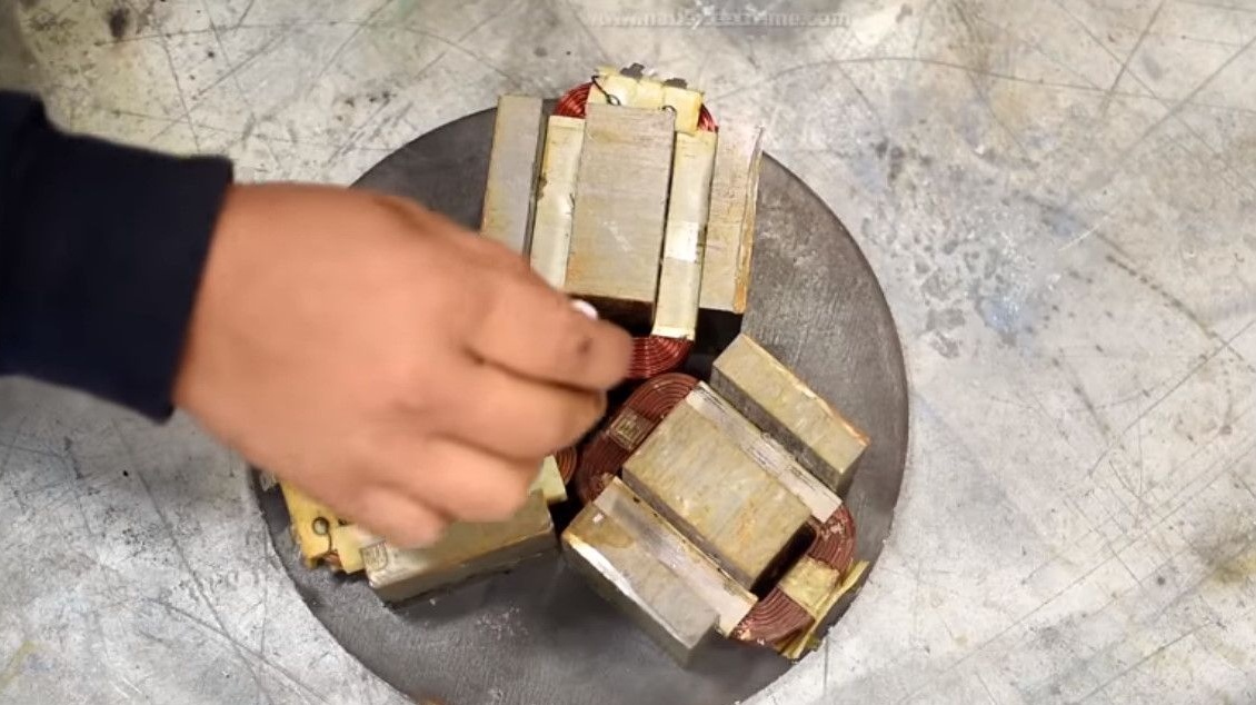
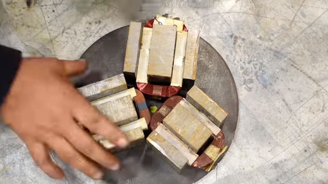
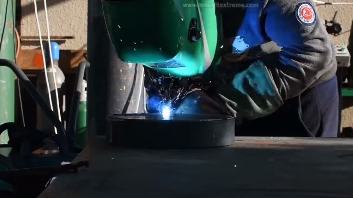
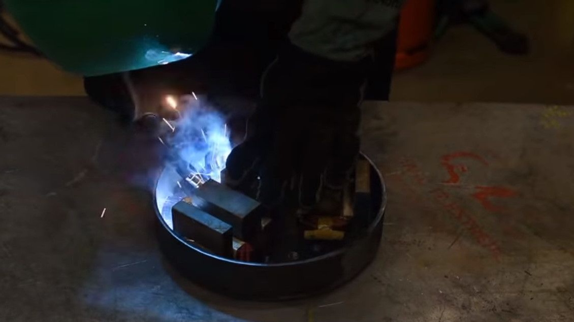
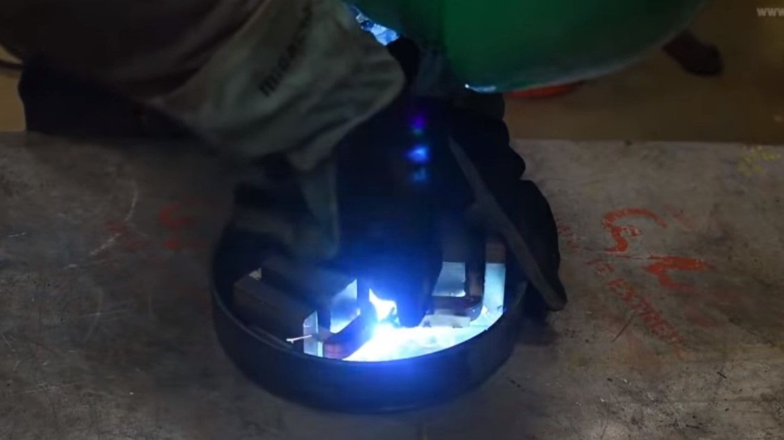
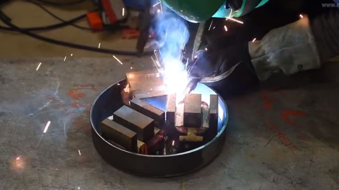
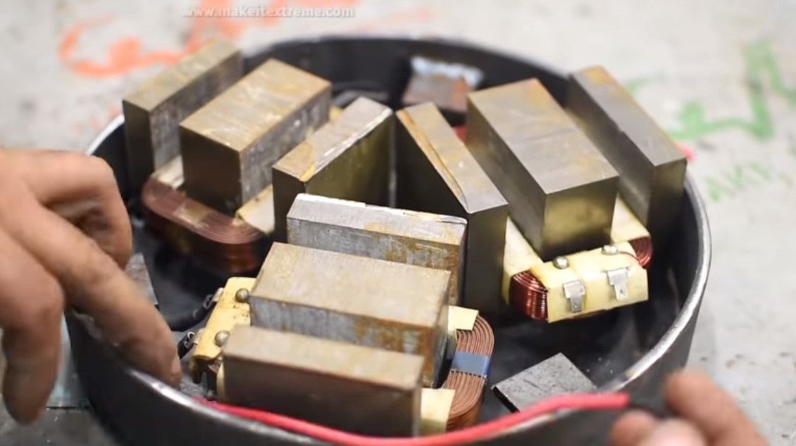
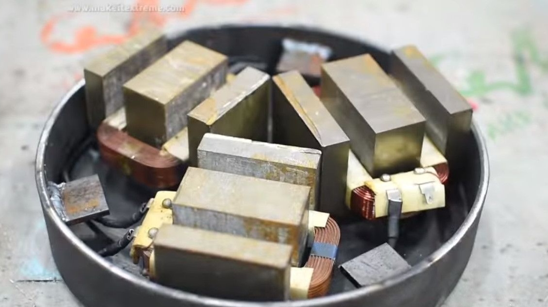
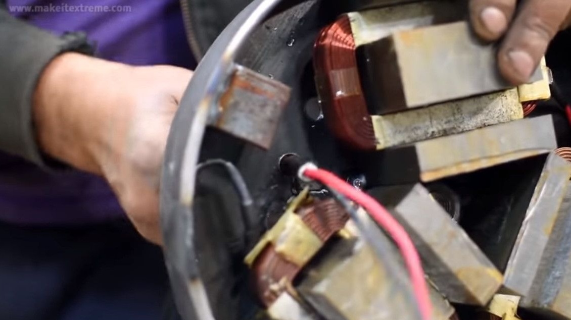
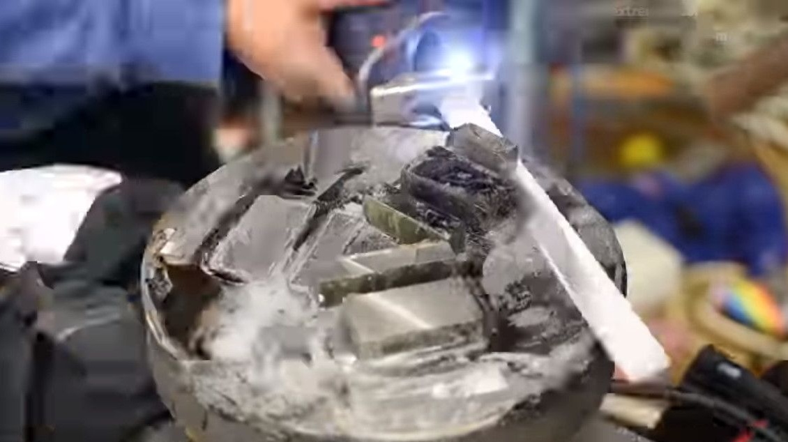
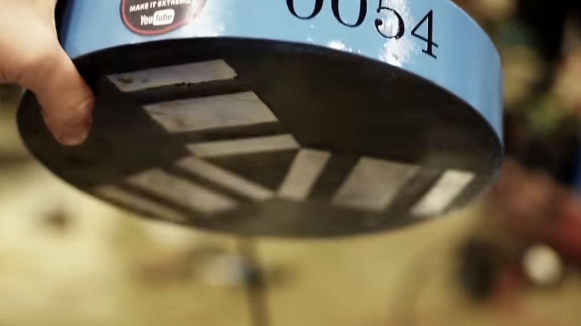
Arranges transformers in their places.
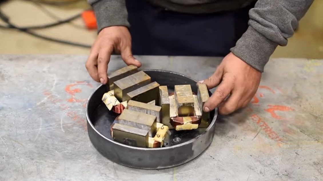
And it very well welds them to the base, so that they would not be torn off.
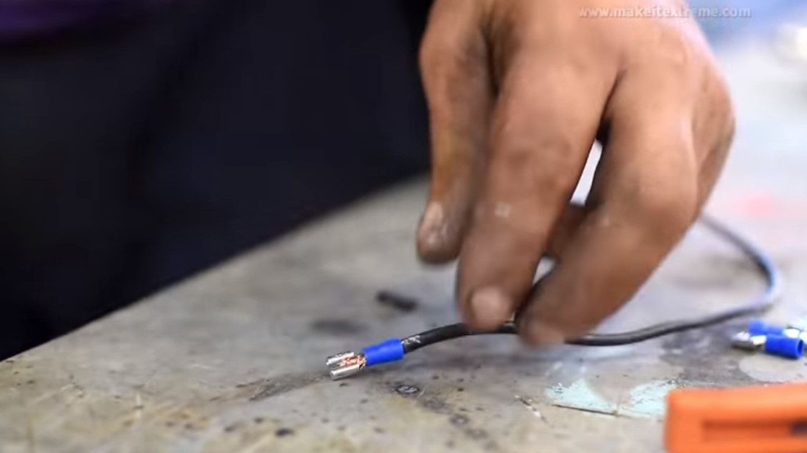
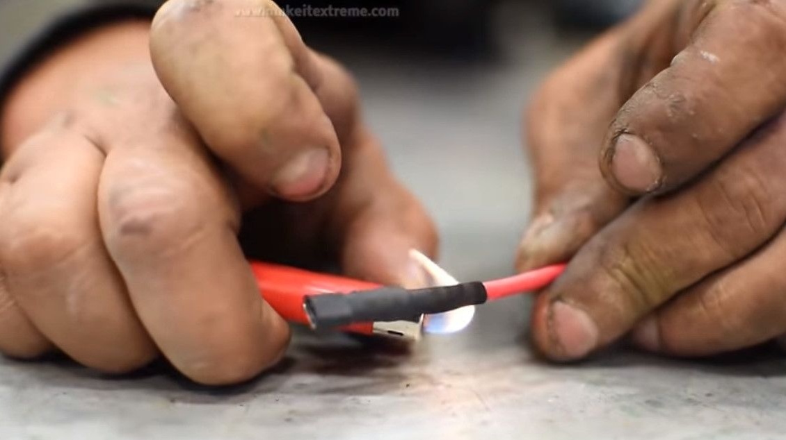
Proceeds to the electrical part.Stripping wires.
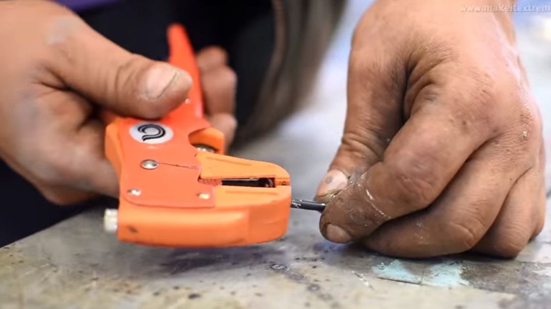
He puts on crimp terminals, clamps the stripped ends of the wire in them.
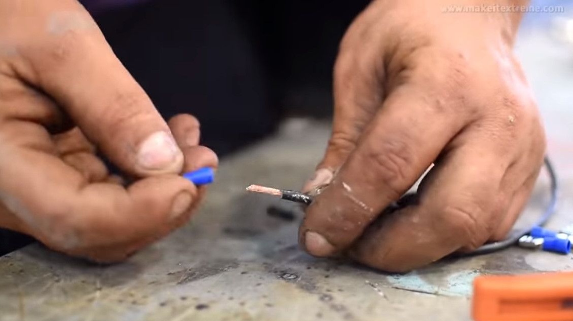
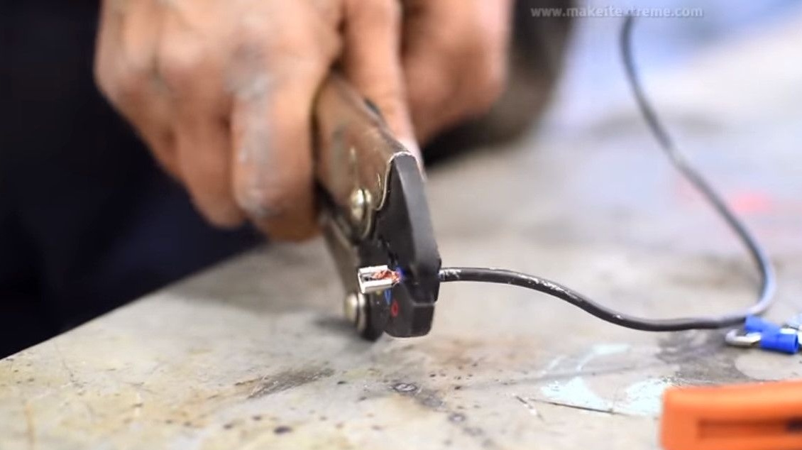
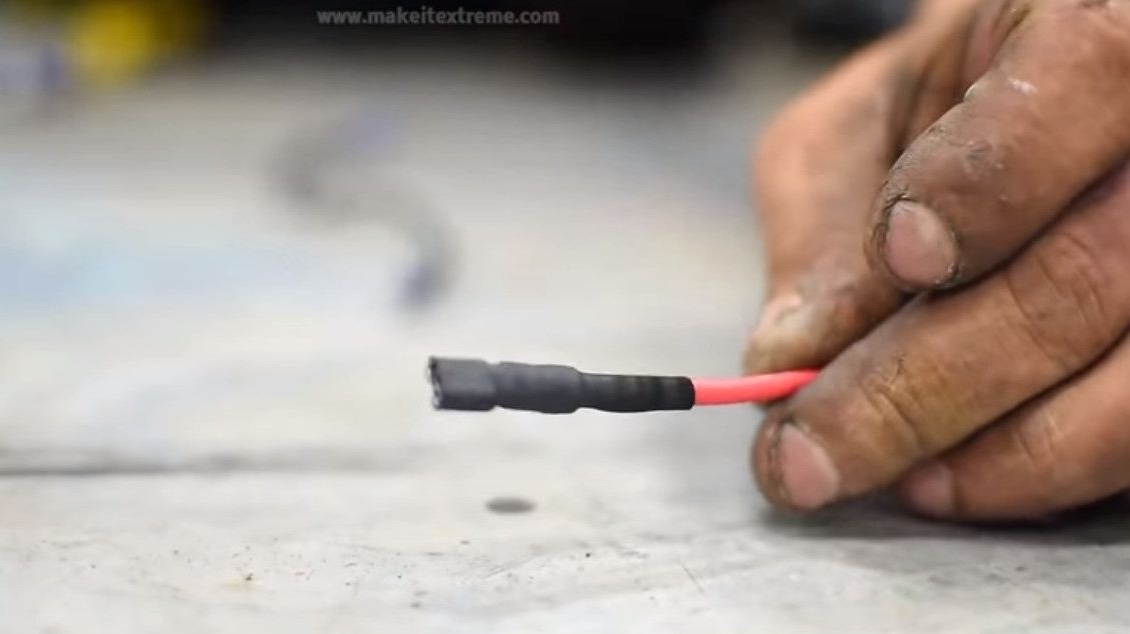
It turns out four connecting jumpers, crimped on both sides.
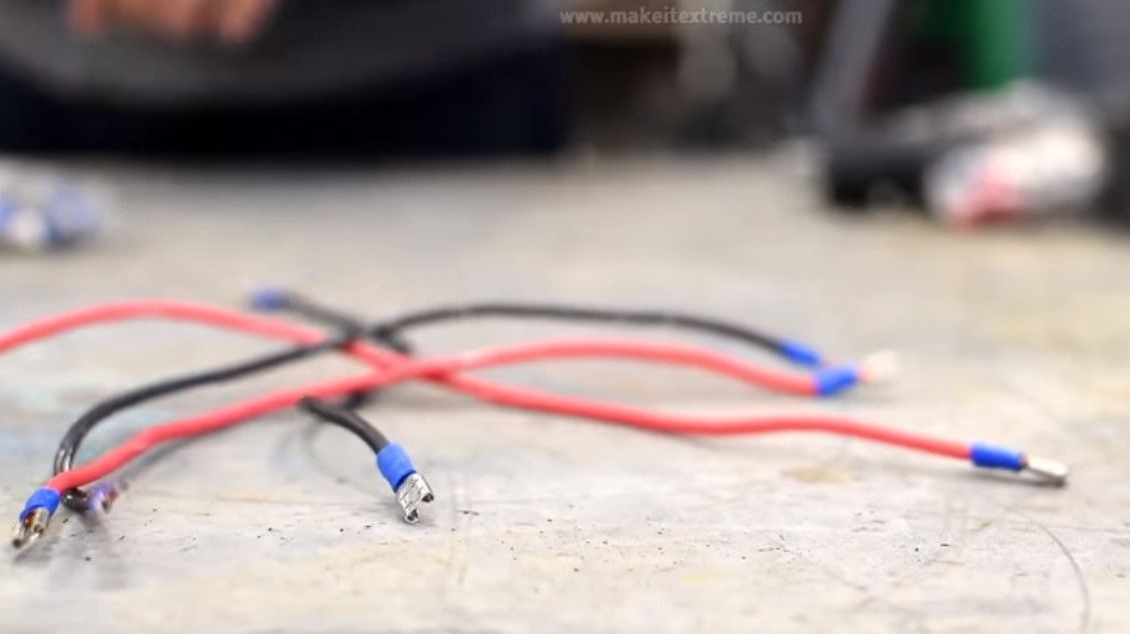
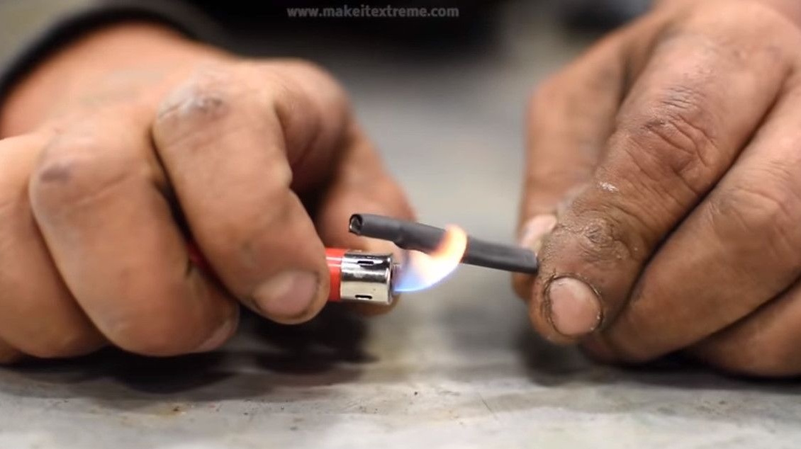
In addition puts on a thermoshrinkable tube.
Connects transformers.
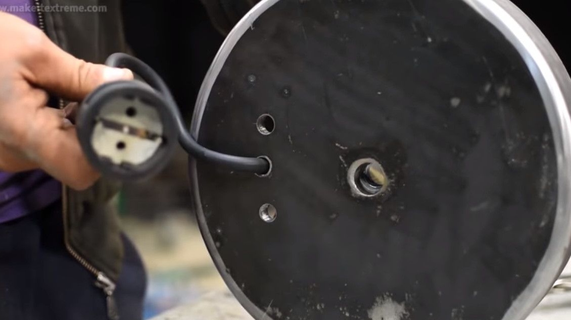
Through the previously made hole, the lead-in wire passes.
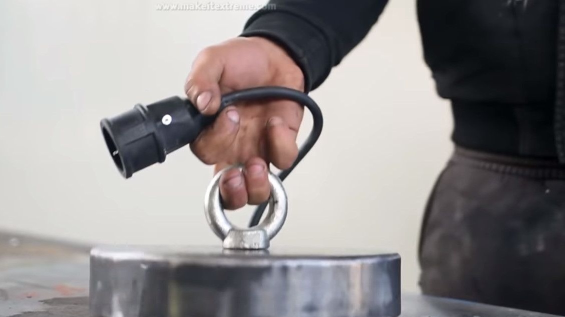
An outlet is installed at the end of the wire, not a plug. This is done so that no one would plug in 220, because the device’s power supply is only 24 Volts DC.
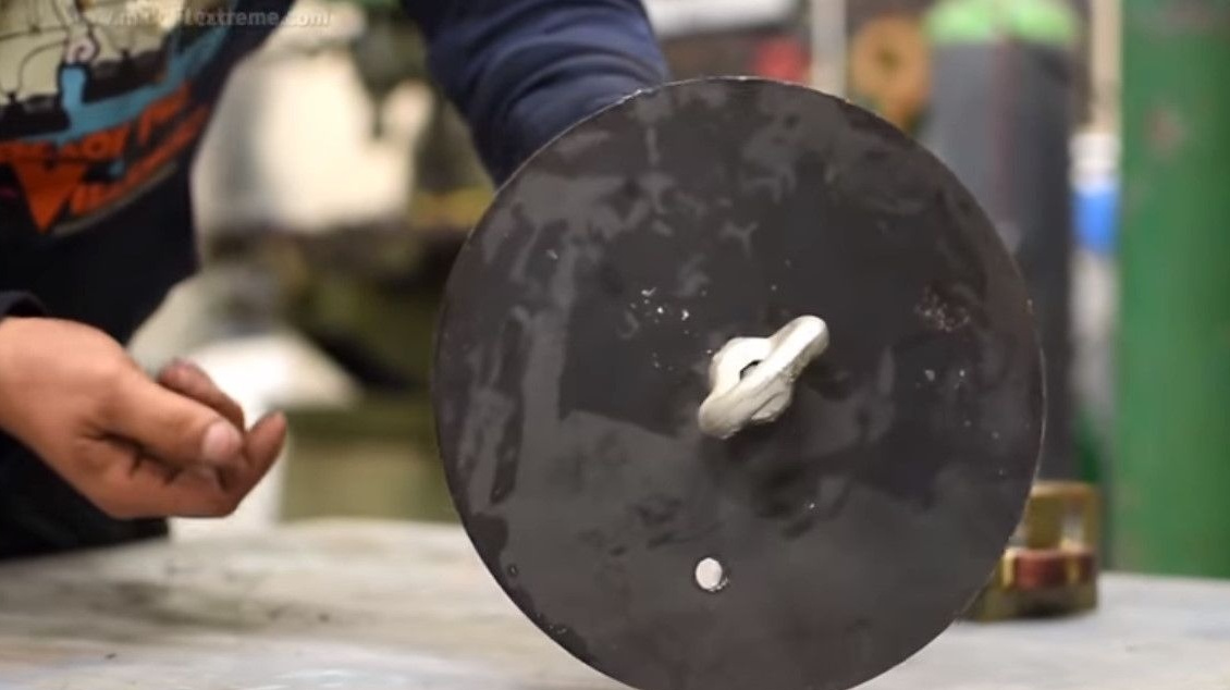
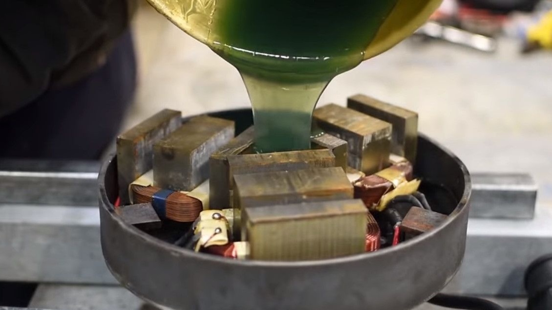
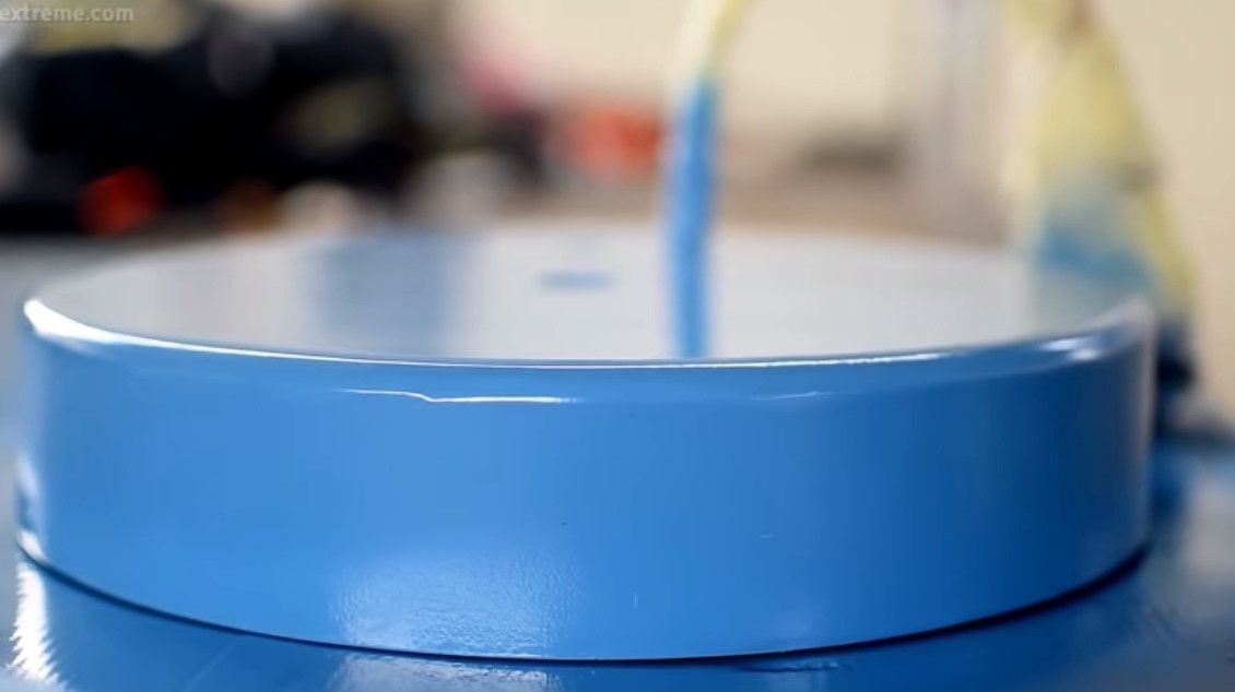
Having sealed all the holes, mixes the components of the epoxy resin and, having thoroughly mixed, fills it into the body.

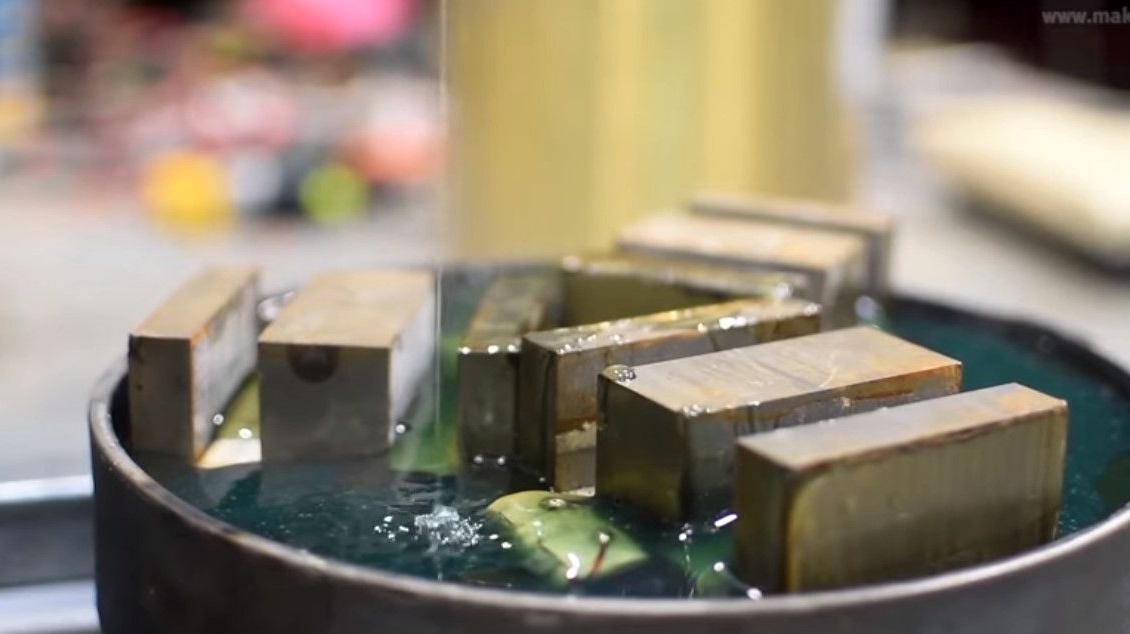
It turns out here is such an almost finished product, it remains a little refine.
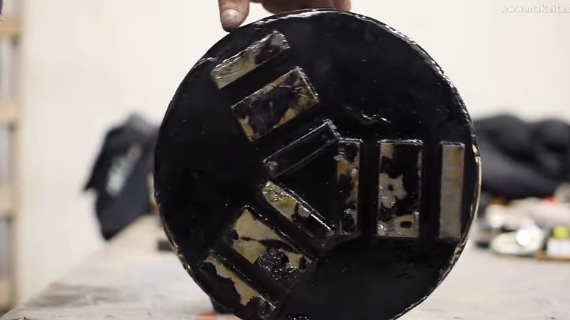
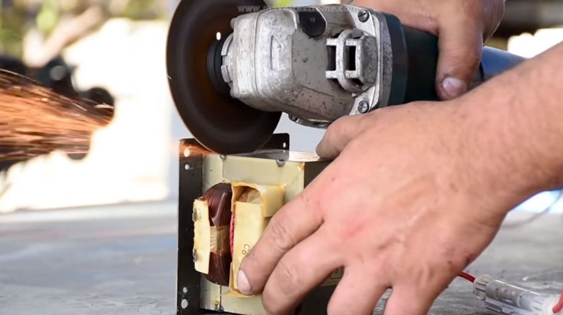
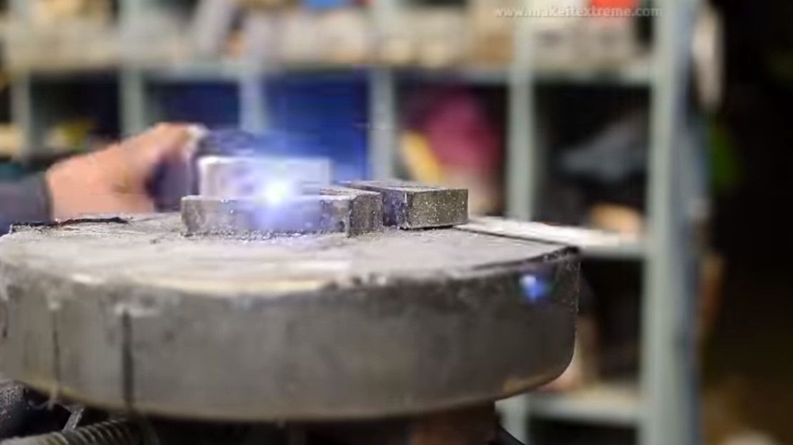
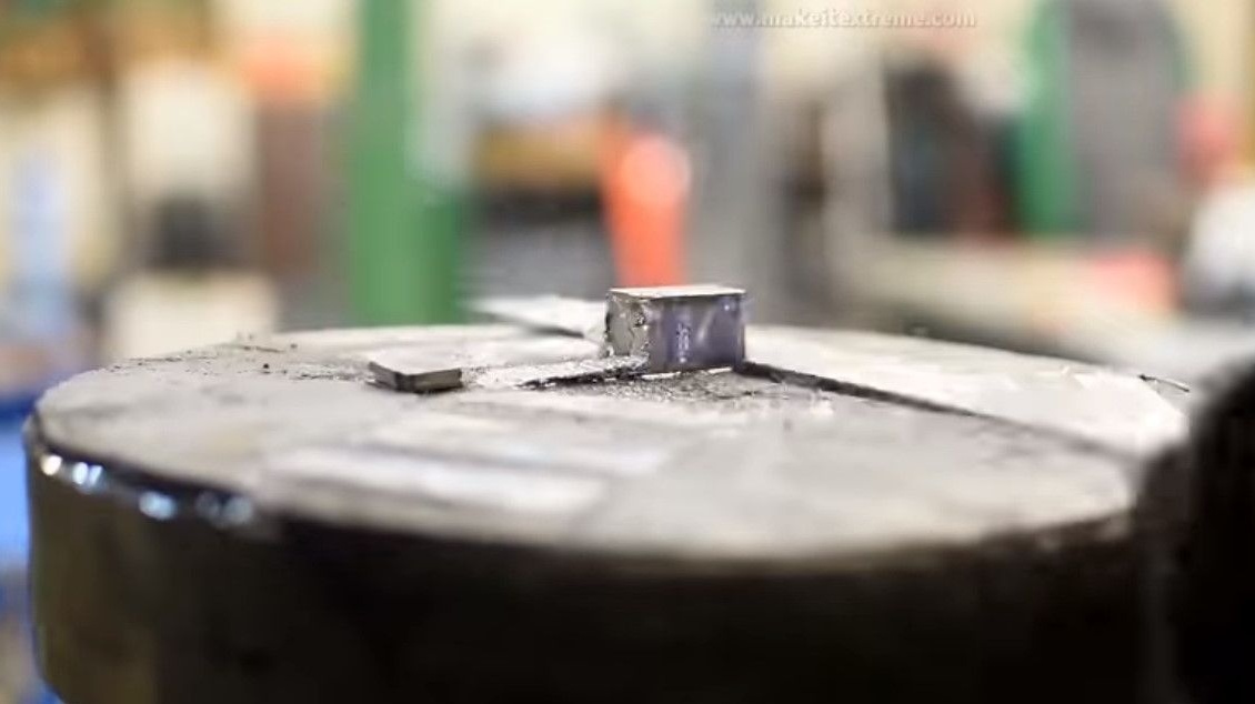
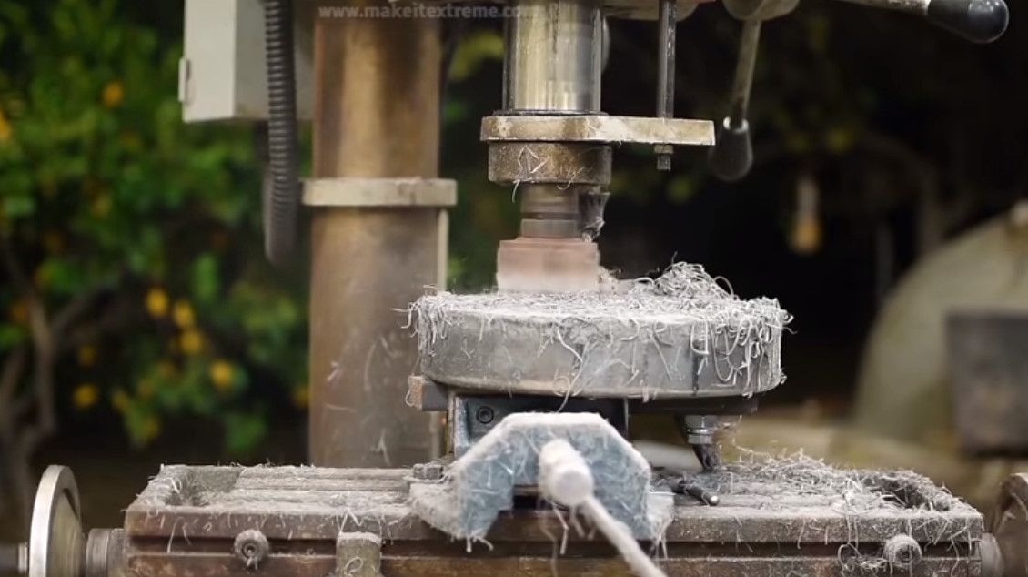
Cuts the protruding edges of the cores.
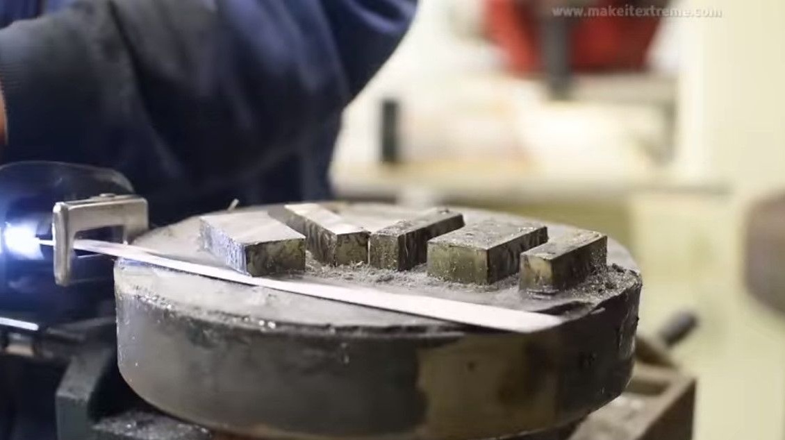
Levels the working surface on the milling machine.
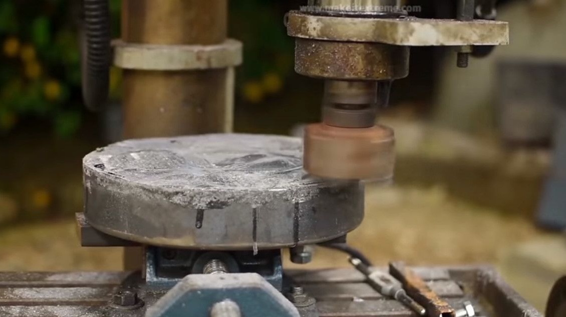
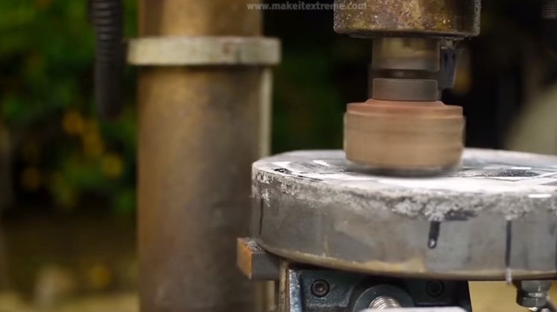
Appearance after stripping and milling. The work surface has become smooth.
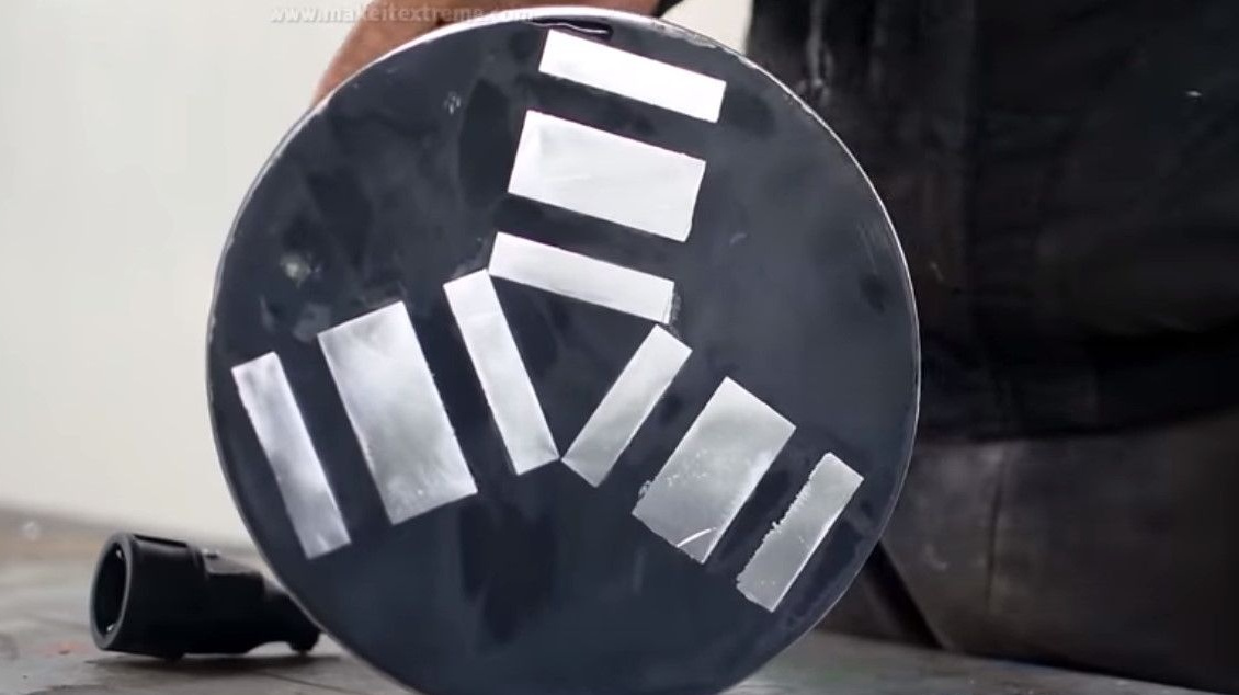
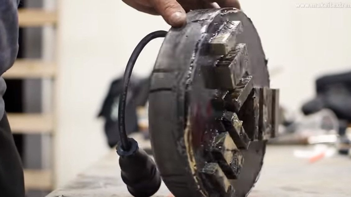
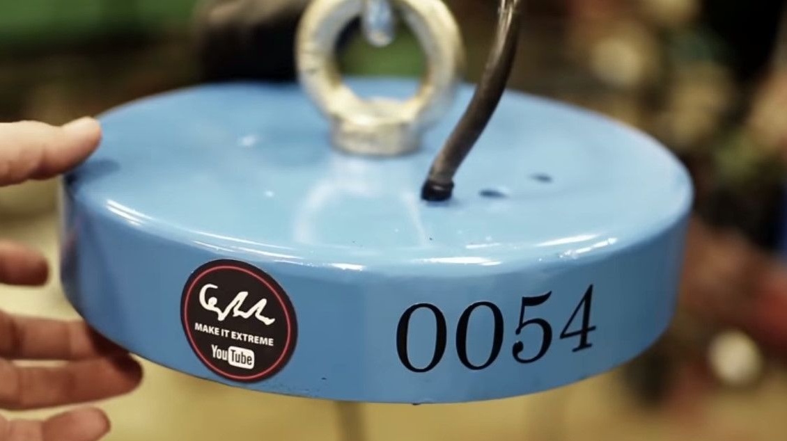
The final painting, the wire the author protected with masking tape.

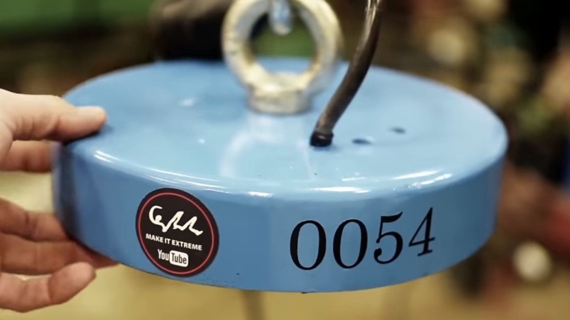
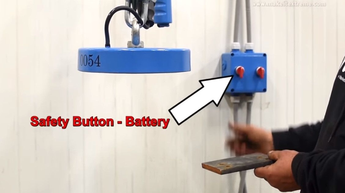
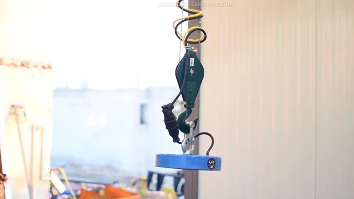
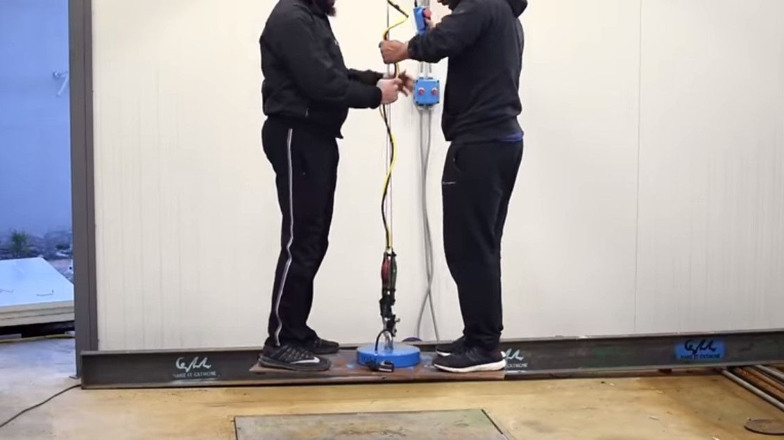
Suspends the finished electromagnet by the hook of the elevator and connects the power connector.


On the electromagnet control panel there are two toggle switches - one from the mains power supply, the second from the backup battery. This is done in case of a power outage, the author in this case turns on the siren.
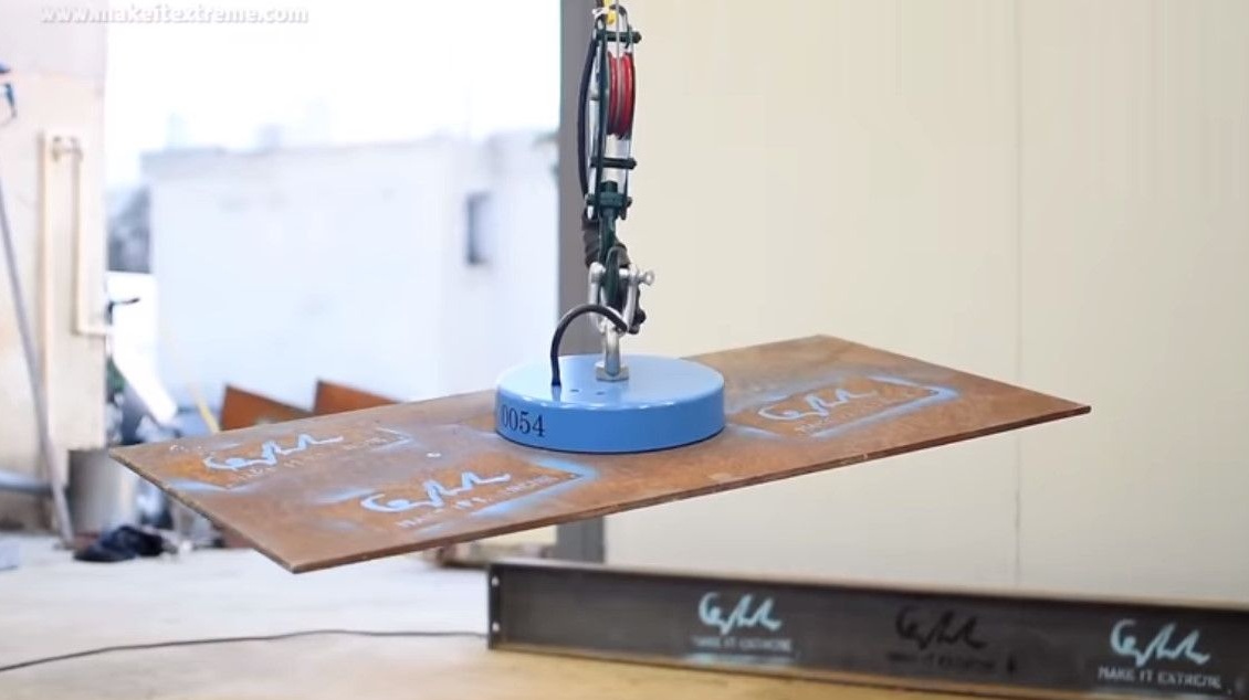
Checks on a small steel plate. The magnet works!
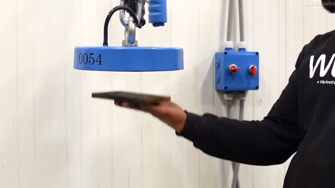
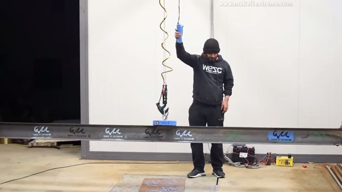
Starts more serious tests. For a start - a larger sheet.
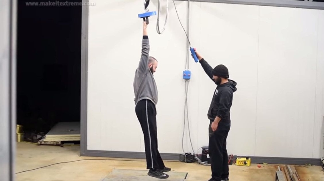
Withstands even two men.
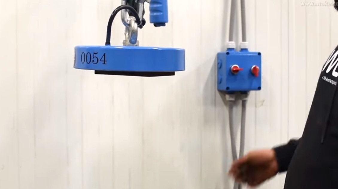
Even with partial contact with the surface of a steel beam, it confidently holds it.
Well, or just like that, you can indulge.
So, the power consumption of the electromagnet is 86.4 watts. Supply voltage 24 V DC at 3.6 A.
Thanks to the author for the great idea and its implementation!
Observe safety precautions!
Good ideas to all!