» Antennas »Antenna Kharchenko for long-distance reception of DVB-T2

DVB-T2 Long Range Antenna


I welcome all those who are not indifferent to the technical, and not only, needlework.

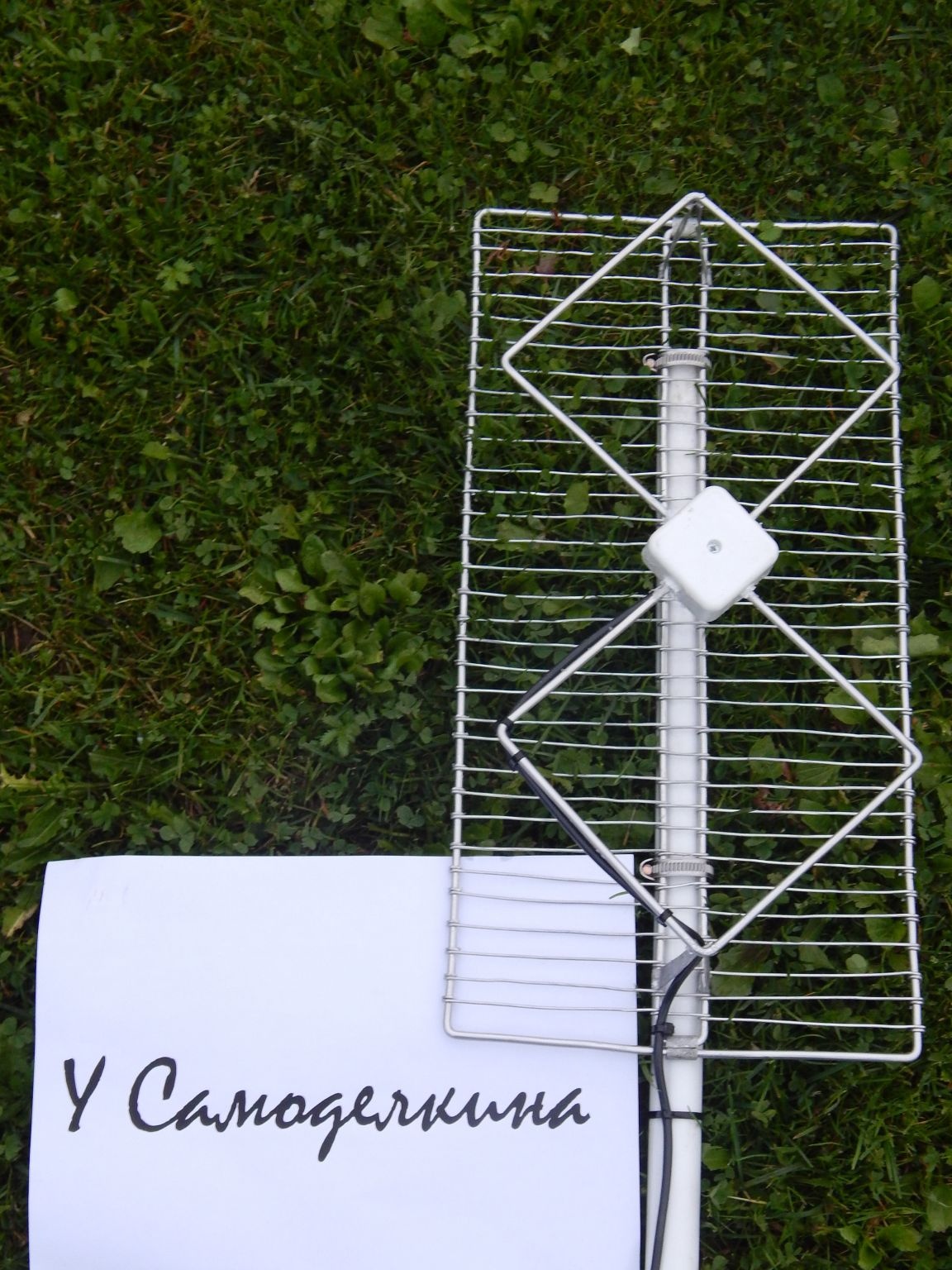
I want to bring to your attention a variant of the antenna for the distant reception of digital broadcasting. Of course, there is nothing fundamentally new in my product, but maybe the idea of ​​combining an amplifier with an antenna is useful to someone. Antenna Kharchenko attracts primarily for its easy to manufacture, good repeatability, sufficient broadband, decent gain (stated up to 9dB with a reflector, but I still have nothing to measure) with small dimensions. In my opinion, it works better than the familiar “dryer”.

So, about the reasons that prompted the desire to create this work. In our city, of course, there is a tower with which the first multiplex of “numbers” is broadcasting and promise to include the second (for two years now), but I want to here and now, like many. In the neighboring city, the second package has long been included, but of course it is not accepted on the indoor antenna, and on the external one without an amplifier, too. I had such an antenna in the garden, recently I gave it to a neighbor in exchange for material, so there was an opportunity to show how I do it.

The production does not require highly deficient materials, even if everything comes out cheaper than the factory one, not to mention super-advertised with the promise of receiving 80 (?) Channels (there are some, I read about this scam).

Materials:
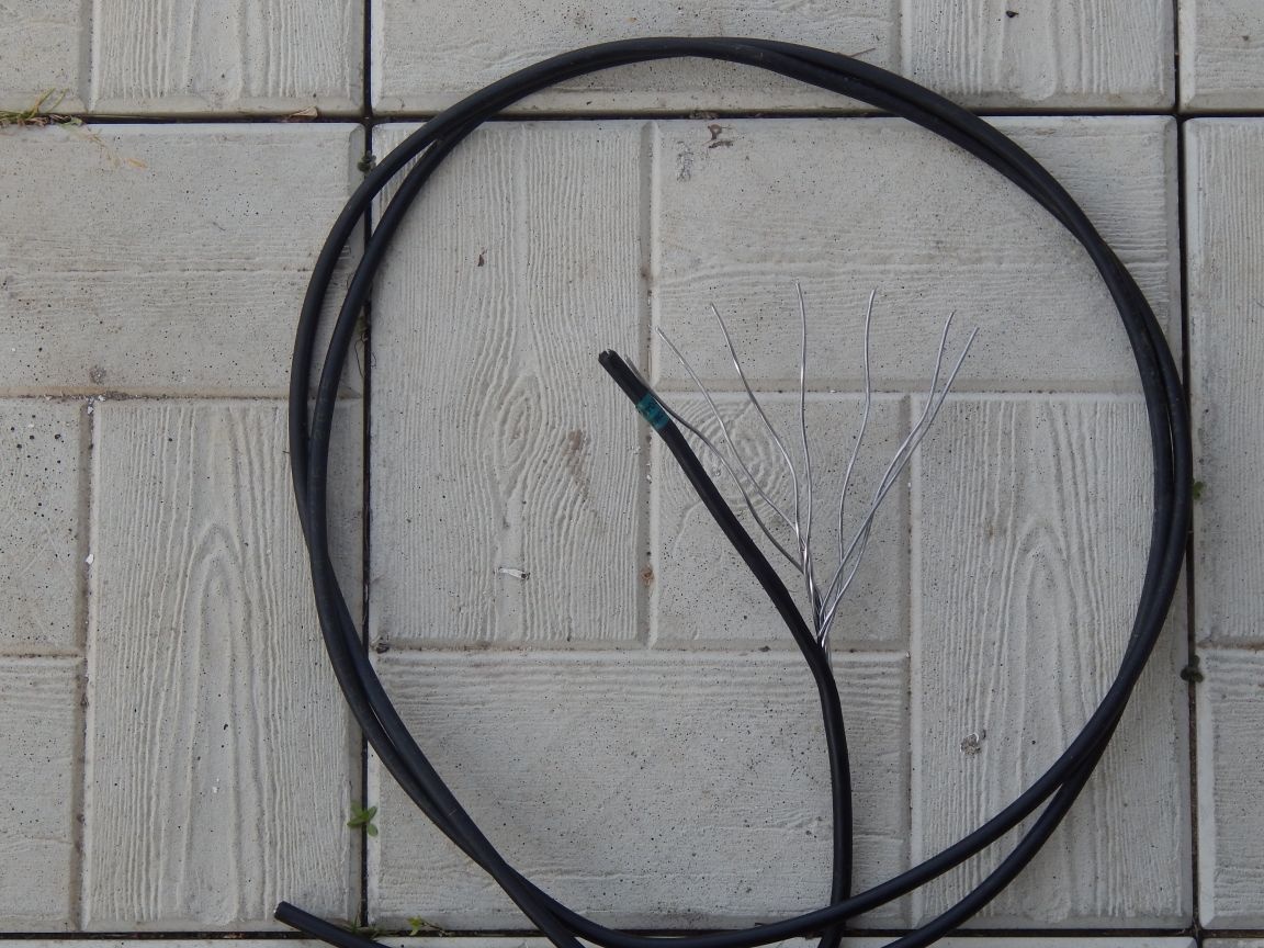
1. The length of the cable 4x16mm² - 1.5m.
2. The piece of wire SIP - 1.5-2m.
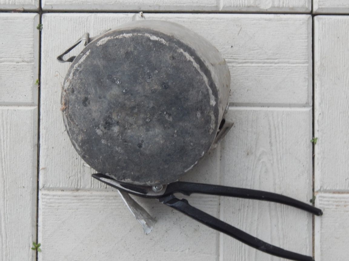
3. Sheet aluminum 1-1.5mm thick. 60x200mm. (I cut from an old pan)
4. Antenna amplifier from the "dryer".
5. Clamps for attaching the antenna to the mast.
6. Silicone sealant
7. And of course the cable and plug.
8. A small soldering box.
9. M5 screws (countersunk head) with nuts and washers - 2pcs.

Instruments:
1. Hacksaw
2. Scissors for metal
3. Drill (I used manual)
4. Drills 1.5 and 5mm.
5. File personal or flat file.

First of all, we are counting our antenna. Not particularly bothering, I took the data on the frequencies of interest to me from. In my city it is 602 MHz (37 channel) the first packet and 770 MHz (58 channel) the promised second. I’m interested in the data of the neighbors -546 MHz (30 channel) first and 498 MHz (24 channel) second multiplexes, so I’ll make an antenna on them. The obtained frequencies, or rather the average frequency, were substituted into the online calculator from and received the required sizes.

At the next stage, we prepare the material - strip the cable

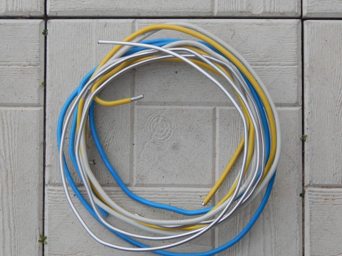
and SIP for bare wire.

We extract a piece of sheet aluminum from an old pan.

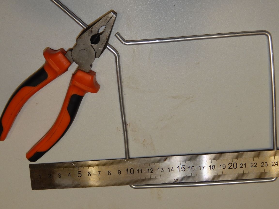
From the cable core 16mm² (ø5.1mm) we use the pliers to bend the “eight” antennas.

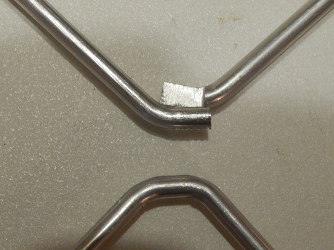
We make the overlap of the G8 junction, grinding off half the diameter with a file.

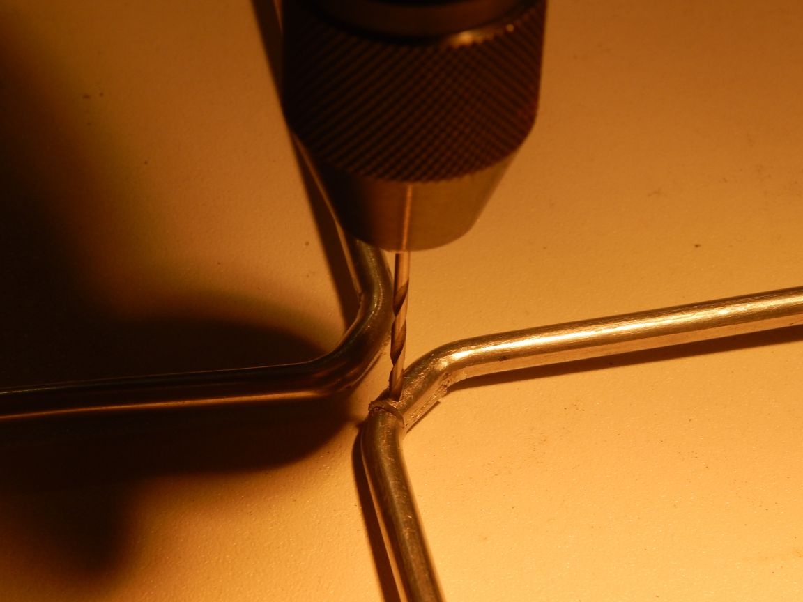
Connection points are drilled ø1.5mm for rivets.

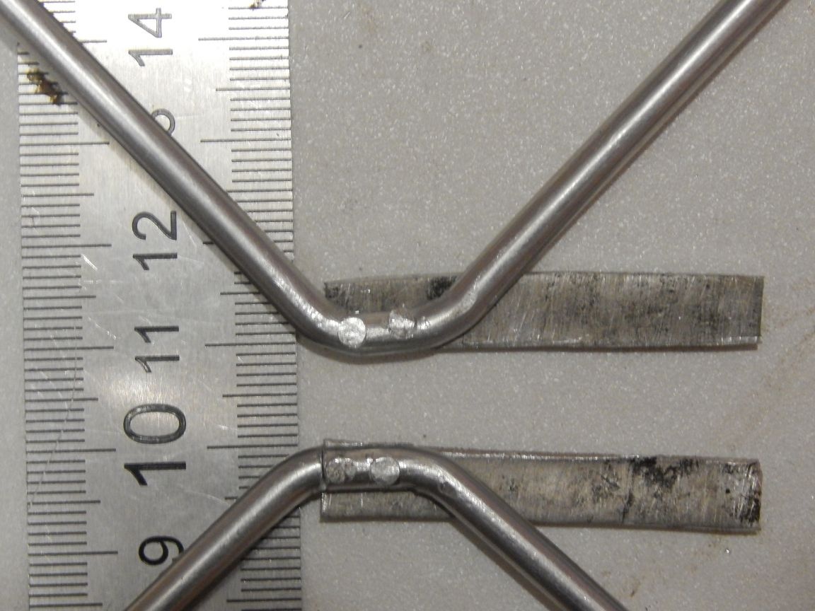
We rivet to the junction of the cable strips of aluminum with a width of 7 mm, a length of 50 (with a margin).

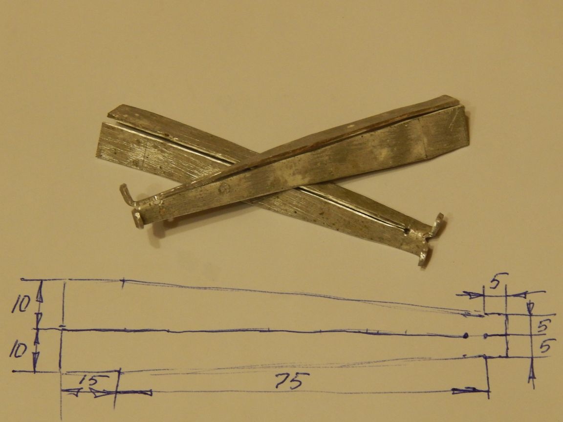
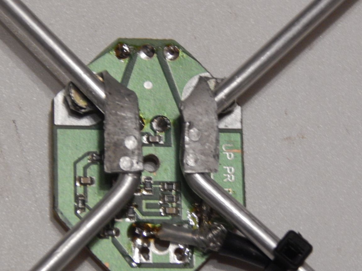
We bend the strips in such a way that the amplifier can be docked to them with screws.

In the strips we drill holes ø5mm for the screws that secure the amplifier, roughly speaking in place, using the amplifier itself as a template, maintaining a distance of 10mm (or whatever is calculated) between the plates. Countersink holes to a diameter of 7mm (diameter of countersunk screw head).

The next step I would call a mockery of the amplifier.

The amplifier in this design is not a luxury, but a means to push a weak signal through the cable, in which it would attenuate on the first meter, to the receiver.

Since he didn’t fit into the junction box in terms of dimensions, and it was necessary to insert it, his edges and the standard cable fastening were simply barbaric — metal scissors — cut to the desired size, and a hole for a self-tapping screw was drilled in the center of the board. The vital organs of the amplifier were not affected during this execution.

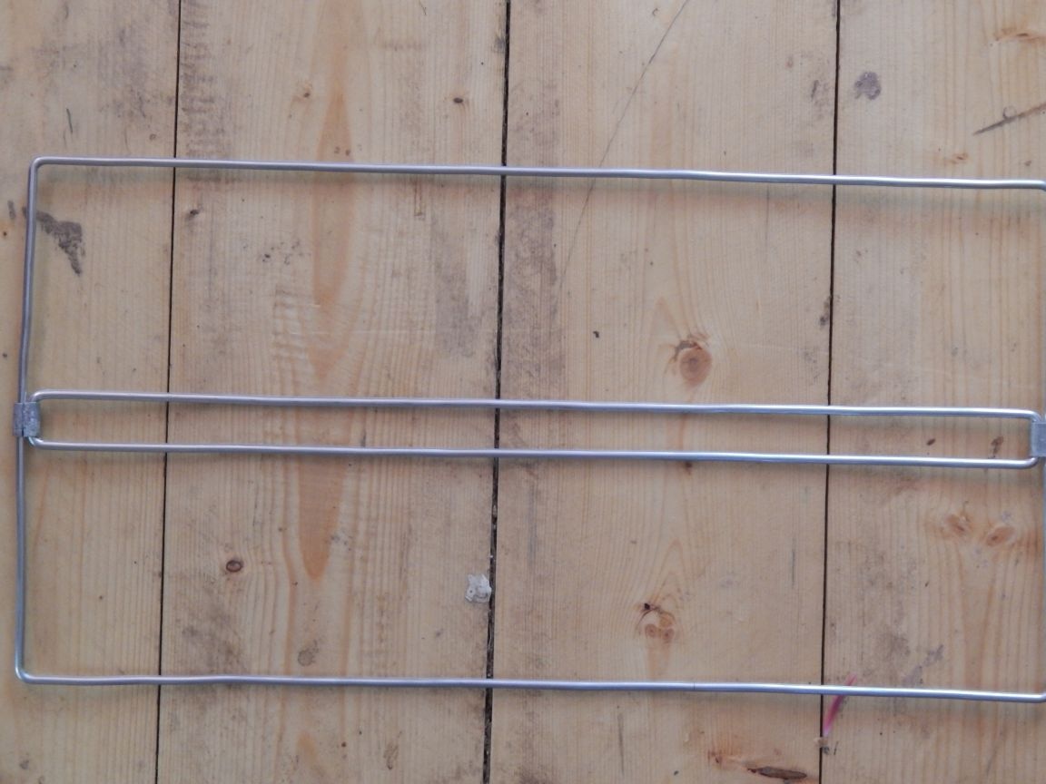
The antenna reflector is also made according to online calculations. The frames are bent from the same cable core as the antenna. The large frame is curved in the design dimensions of the reflector, and the small one is designed to attach the antenna to the mast, brackets (metal insulators) of the antenna sheet and, incidentally, to increase the rigidity of the grating.

The frames are interconnected by a strip of aluminum, followed by crimping with pliers.

We get the following construction:

The lattice is made of single SIP wires, alternately wrapping around the long sides of the frames in 10 mm increments.

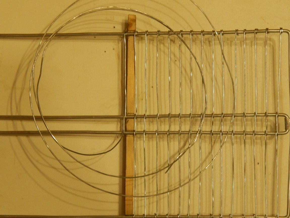
In order to maintain the lattice pitch and size (to tighten the sides of the reflector in the hourglass) I recommend making a template from a 10mm rail by sawing in it cutouts for frames in size. By some miracle, I kept the old template (served as a lining for the chest of drawers for two years), so I don’t show how to make it, and so it’s clear.

As a result, the reflector looks like this:

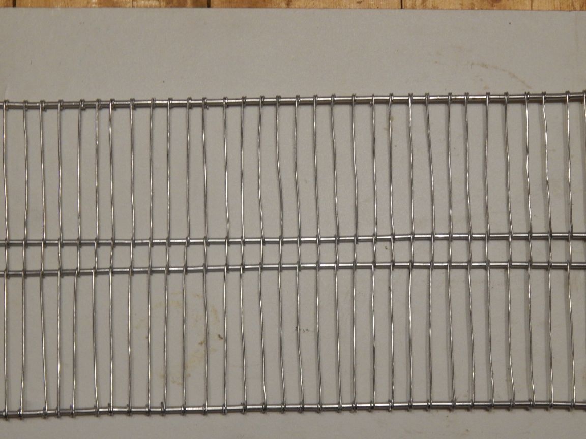
Reminiscent of a fridge grill.
In general, of course, you can do without a reflector, but in my case it was necessary not only to increase the signal of the distant station, but to weaken the signal of the near one, although an extra gain (in my opinion an incorrect expression for the antenna, the directional coefficient is more correct) would not hurt.

The antenna and reflector connection is made of aluminum brackets (“metal insulators”).

All one-piece connections are made on rivets made of a single SIP core.

The drop cable, in the absence (all the excess has already been cut off and sealed off) of the standard mount, is simply soldered to the amplifier board.

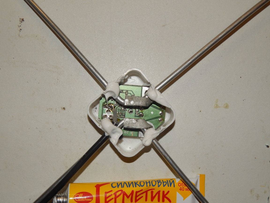
Next, we hide the amplifier in a junction box and, due to severe weather conditions, we coat all joints and holes with silicone sealant.

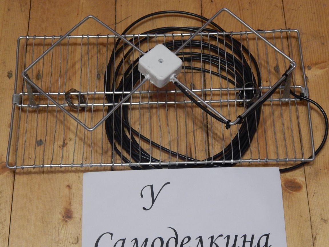
We rivet the antenna sheet through the brackets to the reflector, and we get the finished product:

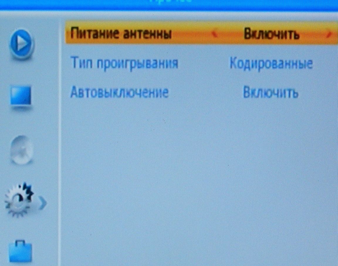
It does not make sense to show the installation and azimuth adjustment, I will show the result of my body movements in the receiver settings menu:
First of all, you need to turn on the antenna power, since the receiver has such a function.

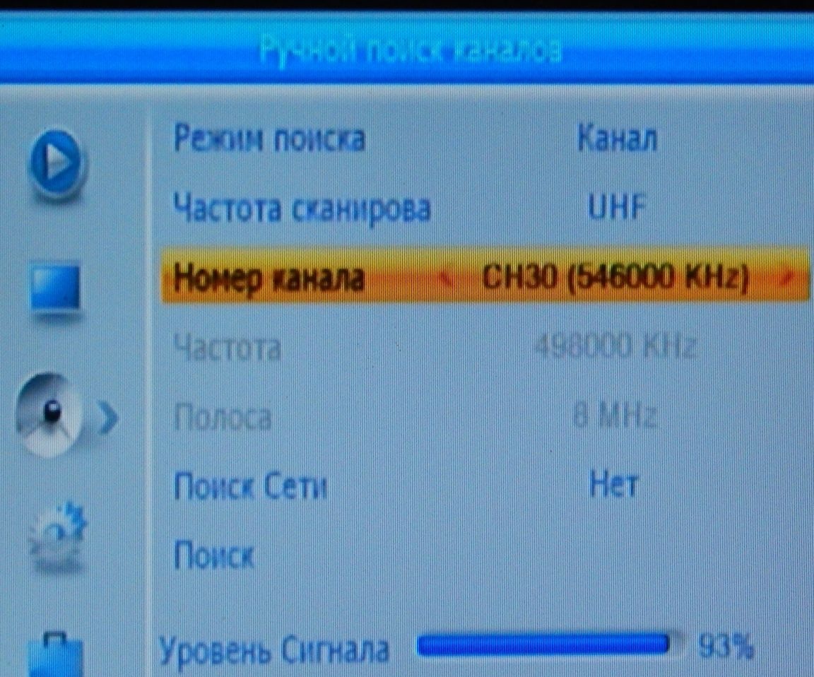
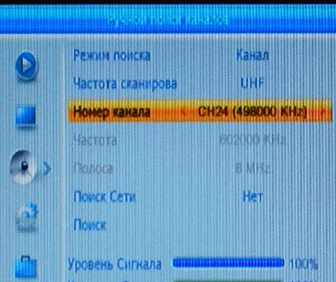
In the settings menu we go into the manual search for channels, set the channel we need and on the lower scale (signal quality) we set the antenna in azimuth. Let me remind you that I need the 24th and 30th channels.


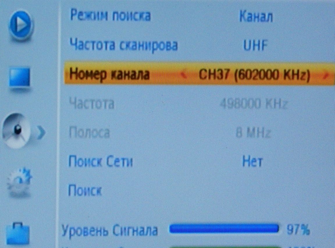
Well, God himself ordered to check the signal of our tower:

Now we turn on auto-search on the receiver, and see what programs it will catch us:
At first he caught me the second multiplex of the far tower, this is exactly what everything was up to.

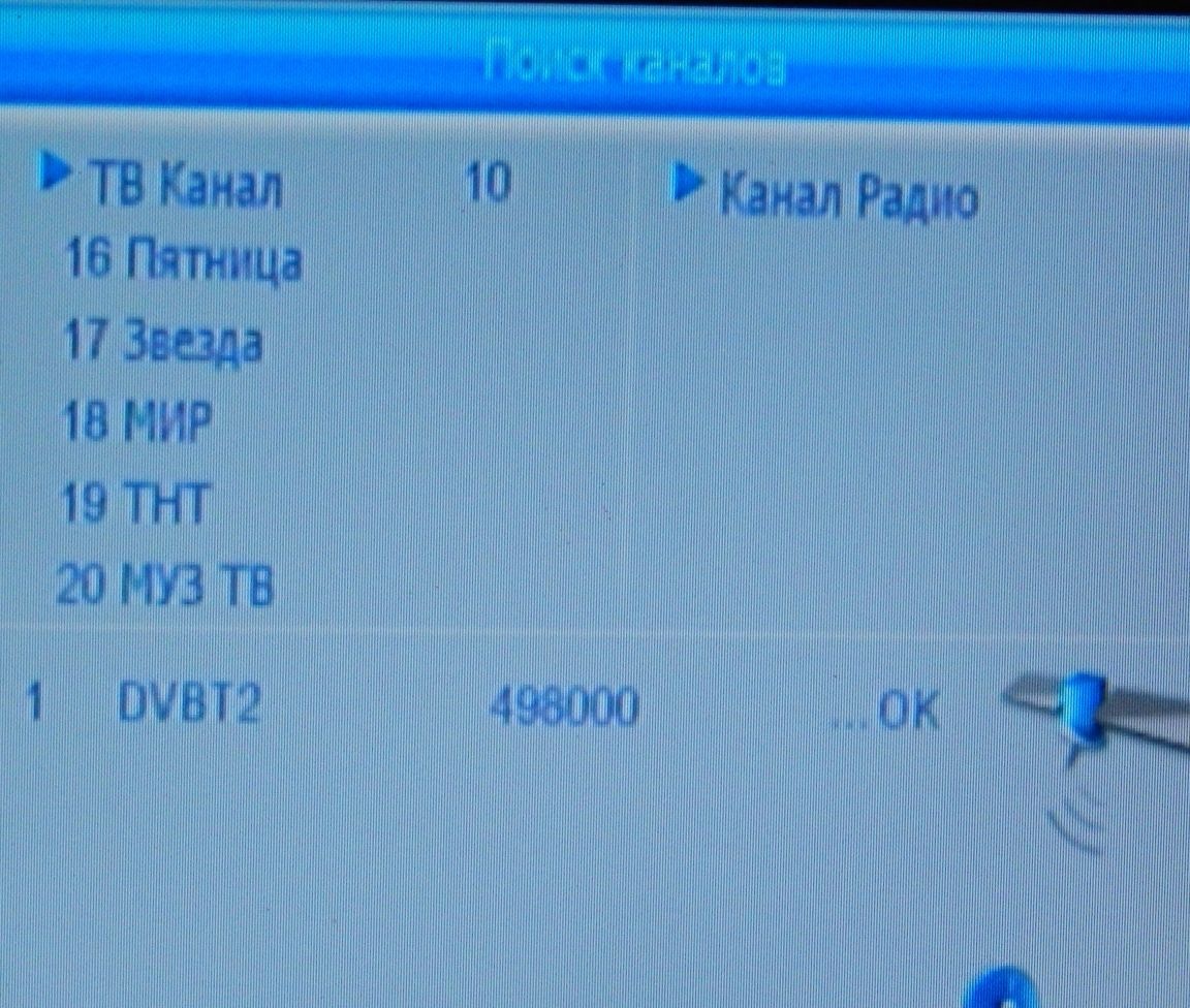
The following two packages are almost identical, they differ only in news programs in different areas.

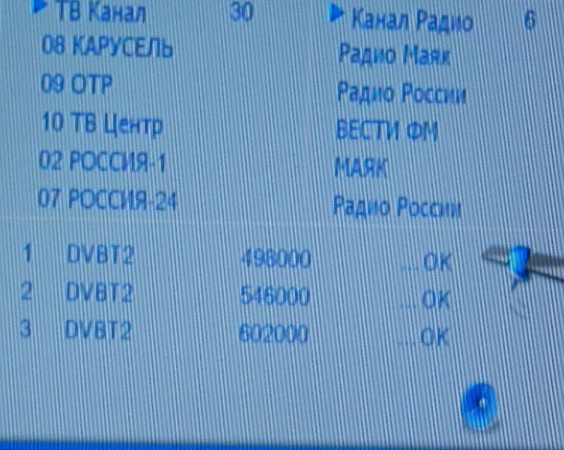
As a result, we have 30 channels, 10 of which are repeated.

Yes, I forgot to indicate the distances to the transmitters.If you believe the information from the interactive map TsETV, then to the farthest in a straight line 21 km., And to ours only 4 km. The elevation angle between them is 74 °.

In the manufacture of the antenna, no amplifier was seriously injured.
8.6
9
8.8

Add a comment

    • smilesmilesxaxaokdontknowyahoonea
      bossscratchfoolyesyes-yesaggressivesecret
      sorrydancedance2dance3pardonhelpdrinks
      stopfriendsgoodgoodgoodwhistleswoontongue
      smokeclappingcraydeclarederisivedon-t_mentiondownload
      heatirefullaugh1mdameetingmoskingnegative
      not_ipopcornpunishreadscarescaressearch
      tauntthank_youthisto_clueumnikacuteagree
      badbeeeblack_eyeblum3blushboastboredom
      censoredpleasantrysecret2threatenvictoryyusun_bespectacled
      shokrespektlolprevedwelcomekrutoyya_za
      ya_dobryihelperne_huliganne_othodifludbanclose
38 comments
Author
What, interestingly, is the Unified State Examination guilty if the device and varieties of antennas do not pass through the school curriculum, especially when I was a schoolboy about a beast like the Unified State Examination? I learned that this is a zigzag antenna from the article “Simple Antenna and DMV Converter” in the journal “Radio”, and I had no reason and no confidence in the editors of the respected publication. Now, regarding the introduced noise, for the “digits” the extra 3-5 dB does not matter, there are two scales in the TV settings: signal strength and quality, so after 50% of the signal strength the difference in image and sound quality is not noticeable. It looks like you are really “off topic” “numbers”.
Judging by your comment, you have a poor idea of ​​the difference between analog and digital TV, and if the noise is critical for the former in the form of ripples and snow, then the strength of the signal is important for the latter, the ADC itself will filter out the noise. This is how to compare sound from scratches on a gramophone record and a CD.
Emote
Yes, the exam is to blame. Your amplifier stands to amplify noise. The resistance of two parallel-connected frames 120/2 = 60ohm without a reflector with it will be less. It will work normally on both 75 and 50 ohm cable. Antenna Kharchenko a kind of loop antennas to zigzag antennas, it is too distant because of the incorrect classification of loop antennas in the USSR. Correctly connecting amplifiers like SWA through a redone balancing SHPTU 1: 1 alteration is minimal. For example, http://vk6ysf.com/balun_1-1.htm. And everything will be wonderful.
Author
Here I already wrote about the difference between the purchased and artisanal antennas, I will repeat the meaning again: you can buy everything, make it more interesting to yourself.
21 km, is that a long-distance reception? In the country there is a purchased log-periodic, with 555 amplifier. 62 km, 3 years, no complaints. Moreover, it stands under a slate roof, so that from the street and the antenna is not visible. Kharchenko did the same, did not like it. With the same amplifier, it works worse.
A biquadrat is a loop antenna with a square reflector. Here is a zigzag antenna
I have already pointed it out here, it is useless! smile
A biquadrat is a loop antenna with a square reflector. Here is a zigzag antenna.
I have been making such antennas since the advent of digital television. At first I did double (4 squares) with an amplifier, then like, with you with an amplifier. Now it’s just two pieces of 4-6 mm wire, 50 cm long, square, or round, plus a drop cable. With an unstable signal, I add a reflector in the form of a metal plate or grid, 15-20 percent protruding beyond the active canvas at a distance of 7-9 cm. The amplifier (in my opinion) cuts the frequencies, introduces distortions, besides the static (not only during a thunderstorm) knocks it out quite often. A few words about tuning the antenna. In our region, the first multiplex - 24 channel, the second - 57 channel! What a setting !!! It's funny when people buy a wave channel, all its dignity is in fine tuning to the resonant frequency. This was true when there were 2 TV channels.
Author
Of course, you can solder, but I wanted to show how everything is made from improvised materials so that I can repeat it. But not everyone will find solder and flux for aluminum, and they will even think that it will not work without soldering.
Well done! I would weld all aluminum joints with aluminum solder.
I'm afraid you might not like it if you
whoever he wants, he will call

On the correctness of the terminology here (and not only here) many copies are broken! smile
Quote: Korolev
"zero potential point"!

Or a donut hole. . whoever wants it, he will call it that. The bagel itself is a drawn “zero” and its middle is a “point of zero potential”. .
ALWAYS be zero
In fact, if we are talking about antennas, then not a "zero", but a "point of zero potential"! smile
At those points at which the author connects the antenna to the reflector - ALWAYS will be "zero" - and completely in fig, than to connect - by a dielectric or a conductor. This can be seen with the naked eye - a square, in one corner the "maximum" - where the cable is connected, and through the diagonal - there must be a "zero" - that’s fffso. .
Author
Absolutely not affected, more details here:

To form the antenna pattern, it is necessary that its elements are phased and spaced relative to each other at certain distances. Moreover, in the case of conventional vibrator arrays, in which each vibrator entering the array is active, difficulties arise in matching with the feeder, especially in a certain frequency range.

The zigzag fabric, due to the peculiarity of its design, has one pair of dots (a — a) to which the feeder is directly connected.

At points (n — n) there is no rupture of the conductors of the antenna sheet, therefore, there is always a current antinode (respectively, zero voltage), regardless of the wavelength. This circumstance allows dispensing with a special balancing device when powered by a coaxial cable (the cable is routed through a point of zero potential) and makes the antenna band spaced, since the half-wave sections of conductors in the region of points (n – n) always have the same current direction, that is, they are in the same direction phase. [/ quote] In addition, a line segment of a quarter wavelength has a wave impedance close to infinity.
Khatul Madan "The connection of the antenna to the reflector is made of aluminum brackets (" metal insulators ")."
Why not plastic ones, does this affect the quality of reception?
Author
And in the Polish de-metering is not the same amplifier worth it? Now compare the dimensions and cost of factory and homemade antennas. Of course, you can buy everything, as Rockefeller used to say - that you can’t buy for money, you can buy for big money, but this is not about that, I actually do my crafts so that my brains do not float with fat, although I can afford it all buy, or order to do.
Simple Polish decimation - this is simple Chinese decimation, and Indian and "Zeisk" and even "Swiss" - I suggest paying attention to the cost. The antenna described in the opus is made of “shit” and therefore is practically free. Long live the domestic manufacturer, and moreover - "self-employed" !!!! Have you ever wondered - why the usual “butterfly” - described in the opus - is not produced by large companies and it is practically not on the market? - its cost. It, the cost - is almost zero in mass production. What is not profitable for large "players". .
21 km catches and simple Polish decimation
Quote: Oldman
the main gain is given by the amplifier itself,
The amplifier is mainly designed to compensate for cable losses, the reception quality with the correct antenna is almost independent of it.
Author
The “wave channel” is too capricious antenna, with an increase in the number of directors, the setup becomes more complicated, and it is also narrow-band. If we are to make a highly directional antenna, it’s log-periodic, almost as good as the “wave channel”.
This type of antenna, which is called in a hurry, the main gain is given by the amplifier itself, which needs to be selected over a range, and for long-range reception you need an antenna such as a wave channel!
Author
whatever one may say, farther than 25 km from one of them it doesn’t work out
This is the case if on the same line. And if the settlement is in the center of the (relative) equilateral triangle?
Quote: Khatul Madan
Look at the map of the central heating network in the Tver region, there are really "bear angles" where 40-50km to the towers.

Do not confuse - the 40-50 km distance is BETWEEN the towers, and whatever one may say - farther than 25 km from one of them you can’t get in any way, unless you go up into space. . Moving away from one, we approach the other. .And they should make full money at the end of 2018 - the TV people still have time and not all the towers still work.
Author
. In Moscow, an antenna with a meter cable works perfectly on the 6th floor, 15 km to Ostankino,
There is no talk about Moscow and the region, there is only Ostankino blocking within a radius of 50 km. with a possible reception "on the nail", and even in the city itself, reflected signals alone will be enough.
It’s better to reduce the cable length than to put an amplifier.
That's right, radio amateurs have the saying, “The best amplifier is the antenna,” as it’s also right that the signal attenuates the stronger the higher the frequency. And it’s also right that the reception conditions depend on the terrain and sometimes it’s enough to raise the antenna by 3 -4 meters to have a confident reception.
The network of towers is such that in central Russia there is no more than 20 km to the tower and all towers have a transmitter power of the order of 10 kW - so reliable reception of the numbers on the butterfly antenna is guaranteed almost everywhere, even where the analogue UHF signal has never been received .
Look at the DTEC map in the Tver Region, there are really “bear angles” where up to the towers 40-50 km., And if the meter range somehow made its way, then the UHF has no chance, and the reception is mainly by satellites.
He made such an antenna a long time ago and experimented a little. It turned out that digital channels are very sensitive to the length of the drop cable. With an increase in length of more than 3 meters - the digital signal disappears completely but the analog signal is accepted. Therefore, I share my results. I place the antenna next to the TV - the dimensions also allow the cable length to be a little less than a meter, Azimuth adjustment - the antenna is connected as a normal UHF to the corresponding TV socket and the corresponding (closest in frequency) analog channel is tuned. Next, just “shift to the“ number ”and turn on automatic tuning .. I think it's better to reduce the cable length than to install an amplifier. In Moscow, an antenna with a meter cable works fine on the 6th floor, 15 km to Ostankino, the Tower is closed next to 9 at a dacha 60 km from Moscow - it also receives local towers and even Ostankino. Even in the Oka floodplain, in the "bear's corner" - according to Paustovsky, this Prioksky reserve 300 km east of Moscow works perfectly without reflectors and amplifiers. such that in central Russia more than 2 0 km to the tower does not happen and all the towers have transmitter power of the order of 10 kW - so reliable reception of the numbers on the butterfly antenna is guaranteed almost everywhere, even where the analog UHF signal has never been received.
Here I have up to 50 km to one powerful transmitter, but within sight, and to another (local) 8 km, but closed by buildings and terrain.
The angle is about 90 degrees. And the channels (frequencies) are one.I go to the far one, but at sunrise the reception starts to fail, then everything normalizes
Bi-Loop antenna with SWA amplifier.
Quote: Khatul Madan
For a figure, it’s hard to determine by eye - the signal is either there or not.

In the channel settings you can see if the TV allows.
At least spray open the board. and cable edges. Then seal - do not seal, and the cable "pumps" moisture
The edges of the cable must also be varnished.
IMHO.
Author
I already made this antenna “over the top”, even the reflector template remained, before that I had tried to remove the transformer altogether, and set the RG-6 cable - I didn’t see the difference. For a figure, it’s hard to determine by eye - the signal is either there or not. Perhaps at longer distances it matters. I generally have a cable of 50 Ohms, a length of 8 m. But already tested, despite all the losses it works, I just kept silent about this “jamb” believing that a 50-ohm cable is not very common.
Cable is desirable RK-75. And you can lead it right out of the box behind the bars (reflector).
In the applied amplifier (SWA-555), there is a trans with input in the input. 300 ohm. Therefore, it is desirable to do the antenna design with an approximation of 300 ohms. Although, of course, a powerful amplifier will “push through” - it will amplify and is not coordinated to the end.
Sound work, sensible description, I won’t ask about the cable!
Author
By the way, the tube of silicone almost all gone, anyway, after all, the opened one will dry out.
Author
So I finally pumped it in silicone only after checking. The photo just shows what needs to be done.
When hardening, the epoxy may tear off any part. But what I really would do differently was to configure before sealing, not after.
Author
It wasn’t at hand, and then, the epoxy was too fluid, then it would be necessary to coat the entire soldering with plasticine. Well, I pushed the sealant there with all my heart, so the design is already inseparable.
Excellent biquadrat performance. The only thing I would do was flood the entire board with epoxy.

We advise you to read:

Hand it for the smartphone ...