

Specialized glass annealing furnaces are slightly different from classical muffle furnaces - the annealing temperature, depending on the type of glass, rarely exceeds 600 ° C, which eases the requirements for furnace materials, however, in an annealing furnace, an important condition is the uniformity of the temperature field. Both features correspond to an unusual look. In fact, metal is much more thermally conductive than ceramic materials traditional for muffle furnaces. The temperature inside the metal case is much more uniform.
At temperatures below 500 ° C, aluminum muffles are used, which, with the corresponding wall thickness (15 ... 20 mm), provides a particularly uniform distribution of heat. Up to 700 ° C, steel muffles are used, and in critical cases bronze. Steel muffles are best made from heat-resistant and heat-resistant stainless steels operating at high temperature without the formation of scale and deformation [1]. For small muffles, it is convenient to use segments of metal tubes.
When annealing glass, where temperature uniformity is very important, the muffles of special furnaces are placed vertically, in the manner of a pan [2], this allows you to get a uniform temperature field over the cross section of the furnace. Further (thick-walled aluminum (steel, bronze) muffle, vertical arrangement) temperature equalization is possible with forced mixing of air in the furnace and rotation of the annealed product. Such furnaces are used to anneal complex and critical products.
The manufacture of a square-shaped metal muffle with a capacity of about 5.5 l is described below. The muffle is made in conditions home workshop, from stainless steel sheet 1.5 mm thick, by a method of bending, connection - manual arc welding with a consumable electrode.
Justification for the choice of material
Several steel sheets went without marking, however, a number of parts were made of them for wood-fired heating stoves, including those regularly exposed to strong heat (firing door closures), practice has shown that even prolonged (years) cyclic exposure to high temperatures does not cause significant structural deformations. Scale formation is also moderate. The low deformation was probably also promoted by the box-shaped construction of the terminations with a relatively small area of the sides. The design of the muffle is similar.Moreover, a certain experience has been gained in the use of this material - bending, fitting, and welding techniques. All this will facilitate the manufacture of the conceived.
Muffle design
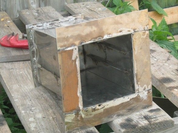
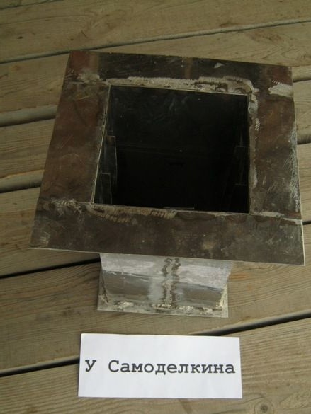
The muffle is a thin-walled (alas), steel box, square in cross section, with a side of 150mm, 250mm long. The main part of the “pipe” muffle is made by bending, from a simple sweep. The bottom is welded to it with a small ~ 10 mm flange and a large (50 mm wide) flange on the front part, covering the gap for asbestos (cord, cardboard) winding, which compensates for the expansion of the muffle when heated, between the muffle and solid thermal insulation.
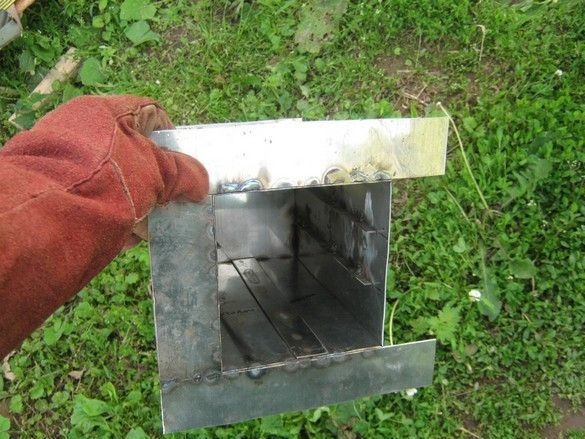
To expand the capabilities of the future oven, there are two pairs of rails on the side walls of the muffle, evenly spaced in height, in the manner of an oven for baking pies. This will allow you to install lattices or special holders (for example, for lampwork-bead spokes) and anneal much more trifles in one cycle, or experiment with uniform temperature distribution by installing two thick-walled metal plates from the top and bottom (left from the cast-iron cooktop wood stove).
The hole for the thermocouple is not provided - it is supposed to seal the thermocouple in view of the high thermal conductivity of the walls of the muffle under the heater, isolating it from the metal with a ceramic plate. Among other things, this will allow to operate more freely with the internal volume of the future furnace, for example, provide for the construction to change the position of the furnace - horizontal-vertical.
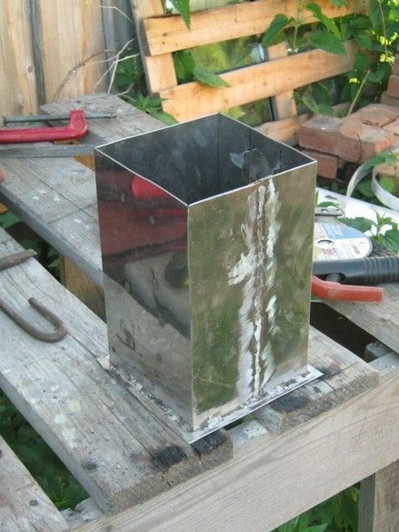
The appearance of the finished muffle can be seen in the title.
What was used in the manufacture
Instruments.
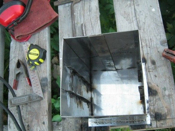
The usual set of bench tools. For cutting sheet steel I used a small angle grinder with an abrasive disk ø125mm. It is highly advisable to use protective headphones and glasses. The marking tool - an alcohol felt-tip pen or a metalwork "pencil" - a scratcher with a sharp hardened nose, a large joiner square, a long ruler. To fix the parts during cutting-welding, several joinery clamps were useful. For welding, a small inverter with accessories was used - cables, a protective mask, leather gaiters, home-made whisking of glassy slag from a small chisel with a handle. It should also include tight non-synthetic clothing and boots. Work was carried out on the street - a good extension cord with a pair (angle grinder, inverter) of sockets came in handy. As always - absolutely necessary, a bit of patience and accuracy.
Materials
In addition to the sheet steel itself, welding electrodes were needed - I used TsL-11, ø2mm, and abrasive wheels ø125mm, 1 mm thick.
To business
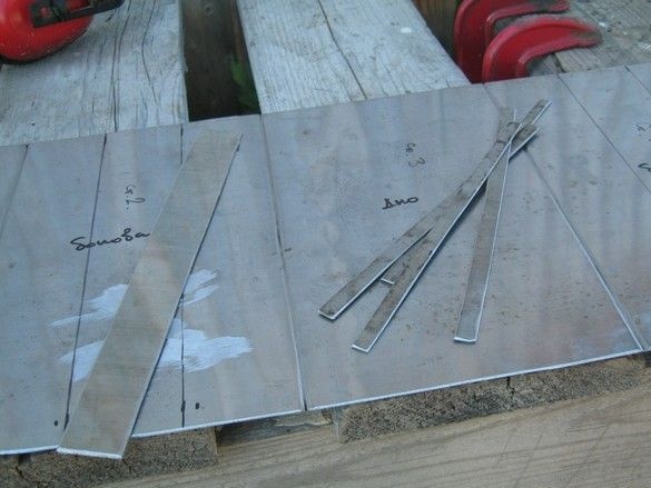
I drew my scan on a suitable piece of stainless steel. With a material thickness of 1.5 mm, the “allowance” for bends, under the condition of trimming (which is discussed below) - 1 ... 2 mm. It does not hurt to mark the appointment of each of the parties.
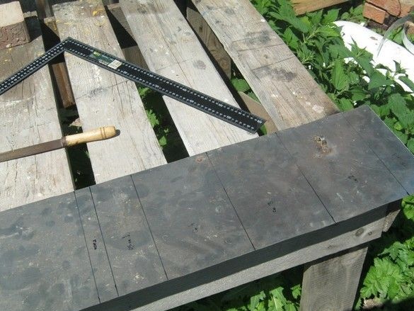
Trimming and cutting the bend. Everything is easily done with an angle grinder in three passes - a straight cut at half the depth of the material and two cuts at a machine position of 45 °. Details are described in the “door closure”.
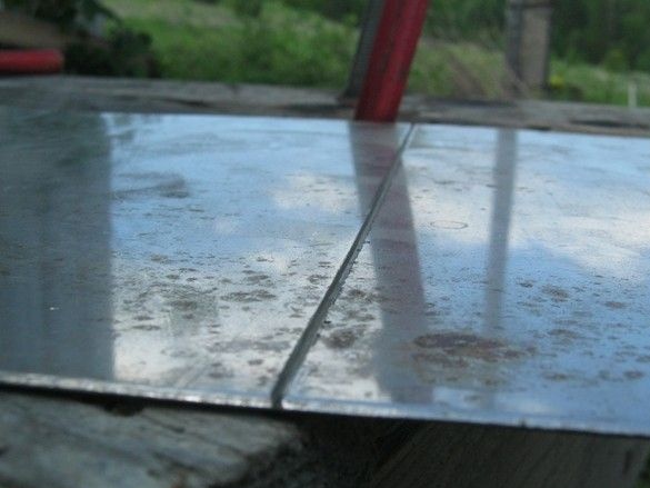
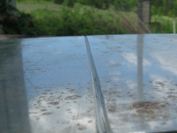
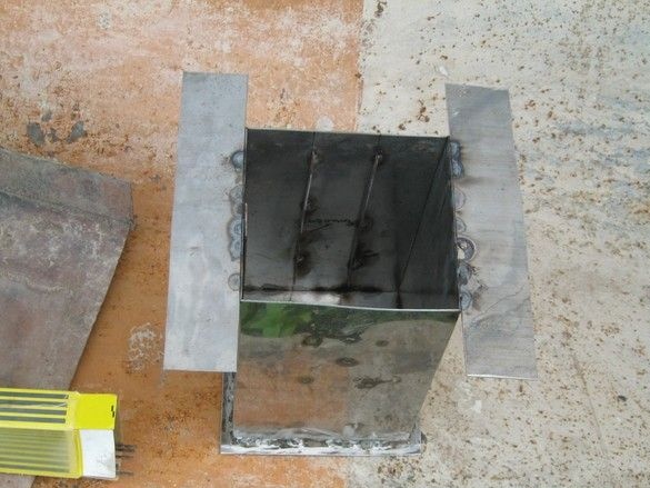
We process in this way every bend point. We leave the bending for sweet, otherwise it will not be convenient to work. The connection of the ends of the sweep is provided on the ceiling of the camera, in the middle, so it is more convenient to weld. Butt welding of thin sheet metal with a conventional inverter, with my modest welding skills - solid burnt holes, therefore, put an additional strip under the welding seam. She did not allow the edges of the steel sheet to overheat, and the molten drops of metal flow inside. Thinner blanks - guides on the sides of the muffle. Visible markings for their welding. The length of the guides, slightly shorter than the length of the muffle - they should not start from the very edge - the furnace lid, as a rule, has a “quarter” around its perimeter to reduce heat loss. She inserts it into the muffle blocking a straight slit.
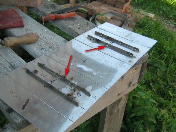
Guides are welded at several points on the marking. The influxes of the welds should be facing the potential bottom, otherwise cast iron inserts or other equipment will be poorly inserted and sit crookedly.Electrodes - TsL-11, ø2mm, reverse polarity, current - if memory serves me right - 45 ... 50 A.
It should be said that thin and long electrodes, as a welder from the word “bad”, to operate, are often inconvenient - the tip of a rather flexible electrode behaves too freely, therefore, for critical places, I cut them in half. The short half turns out much faster and more accurately, and, despite the additional fuss and the increased loss from the technological “tails,” I often resort to this technique. It also doesn’t hurt to pre-heat the electrodes - fortunately, high temperatures are not required for this - a vulgar kitchen oven will be enough.
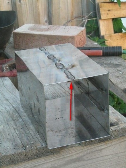
The main part is bent and welded. Lined welding seam. A special tightness from the muffle is not required, it is quite enough, welding "points" or "dashed lines".
Visibly cut and welded bottom. It is convenient to weld from the outside, in many respects for this a small flange 10 mm wide is left. At the same time, it will prevent the heater coil from sliding down. I burned a hole on one of the walls, I hope it is not visible in the photo.
Cutting and welding the outer flange in several stages. First, four plates are cut out with some - about ten millimeters, a margin, then two opposite ones are welded - long. Then, in turn, short ones are adjusted and welded, finally - with a magical “grinder”, we trim the whole composition. It turned out, as if not bad. Yes, welding should be carried out from the inside, otherwise later, it will be difficult to press the door tightly.
A few words on the track.
A metal muffle requires some features when making a wire heater. The muffle is wrapped in a layer of wet asbestos paper before winding the heater. Winding is carried out after the asbestos is completely dried, otherwise the wire will push through a soft insulating layer.
A metal muffle should be earthed without a doubt, it probably makes sense to power the heater from the mains through a residual current device (RCD) or differential circuit breaker with a tripping current of no higher than 30 mA.
The winding of the heater with a certain step is fixed by refractory coating. It is fraught to use liquid glass in its composition - it has some conductivity when heated to high temperatures.
An embodiment of an electrically insulated heater is to place a wire or spiral of high resistance in ceramic beads.
Bibliography.
1. Brower G. (1985) Guide to Inorganic Synthesis. T.1. Chapter 9 High temperatures.
2. Bondarenko Yu.N. Laboratory technology. Production of gas discharge light sources
for laboratory purposes and much more.