
In this article, together with Roman (author of the YouTube channel "Open Frime TV"), we will assemble a universal power supply unit on the IR2153 chip. This is a kind of "Frankenstein", which contains the best qualities from different schemes.
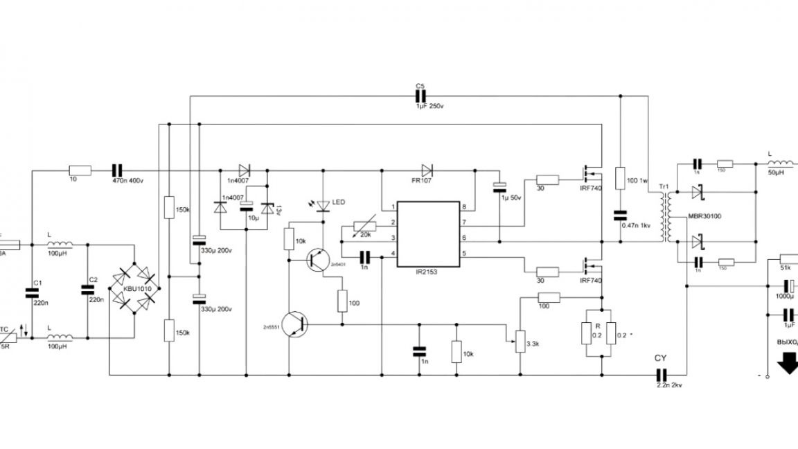
The Internet is full of power supply circuits on the IR2153 chip. Each of them has some positive features, but the author has not yet met a universal scheme. Therefore, it was decided to create such a scheme and show it to you. I think you can immediately go to her. So let's get it right.
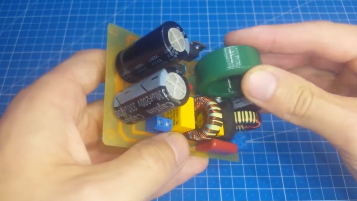
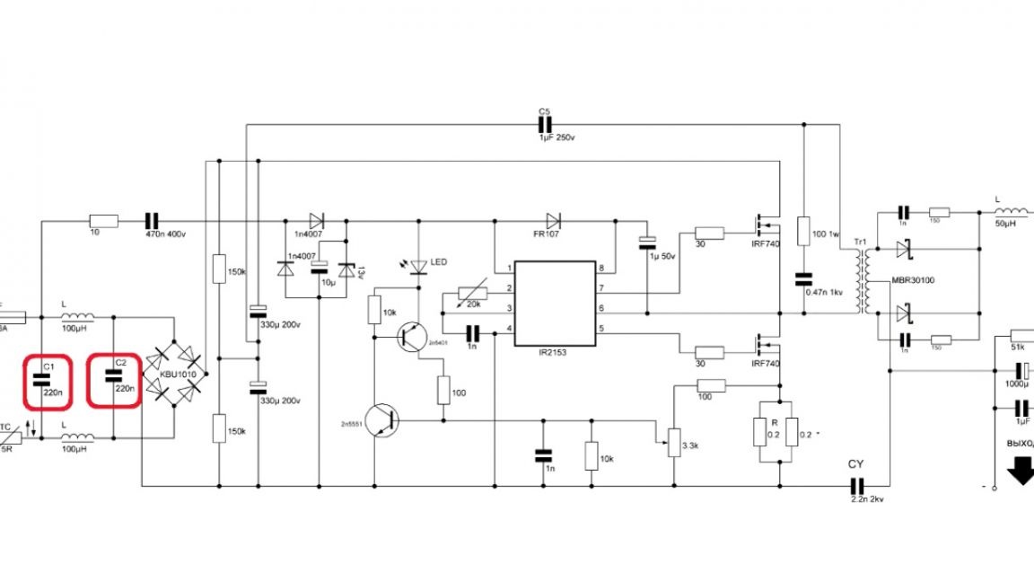
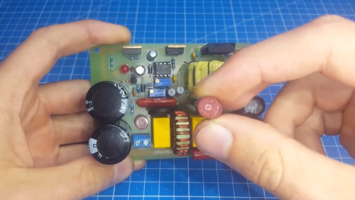
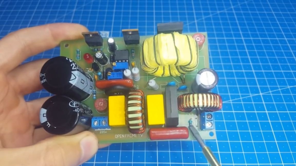
The first thing that catches your eye is the use of two high-voltage capacitors instead of one on 400V. Thus we kill two birds with one stone. These capacitors can be obtained from old computer power supplies without spending money on them. The author specially made several holes in the board for different sizes of capacitors.
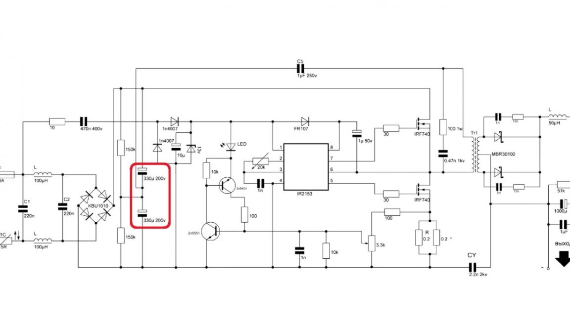
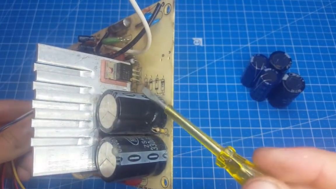
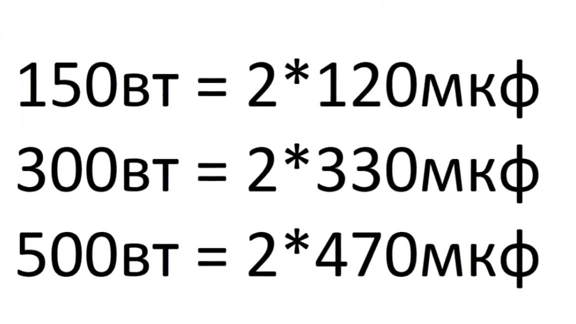
If the unit is not available, then the prices for a pair of such capacitors are lower than one high voltage. The capacitance of the capacitors is the same and should be at the rate of 1 μF per 1 W of output power. This means that for 300 W of output power, you need a pair of capacitors of 330 microfarads each.
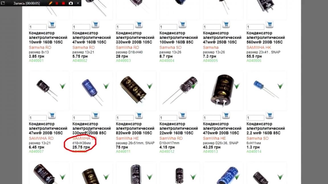
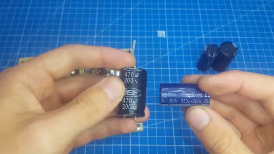
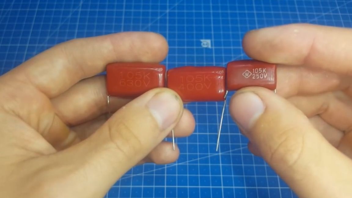
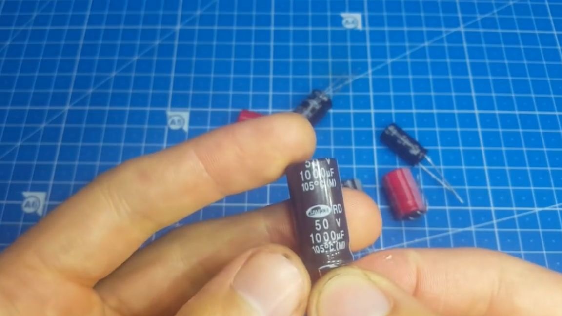
Also, if you use such a topology, there is no need for a second decoupling capacitor, which saves us space. And that's not all. The isolation capacitor voltage should already be not 600 V, but only 250 V. Now you can see the sizes of capacitors at 250V and 600V.

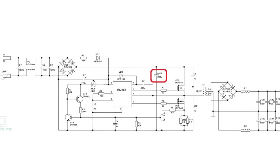
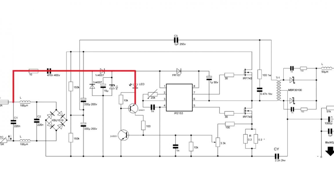
The next feature of the circuit is powering for the IR2153. Everyone who built the blocks on it faced unrealistic heating of supply resistors.
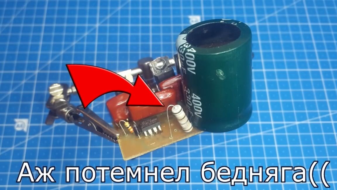
Even if they are set from a break, a lot of heat is released a lot. An ingenious solution was immediately applied, using a capacitor instead of a resistor, and this gives us the fact that there is no heating of the element by power.
The author of this home-made saw such a decision with Yuri, the author of YouTube channel "Red Shade". The board is also equipped with protection, but in the original version of the circuit it was not.
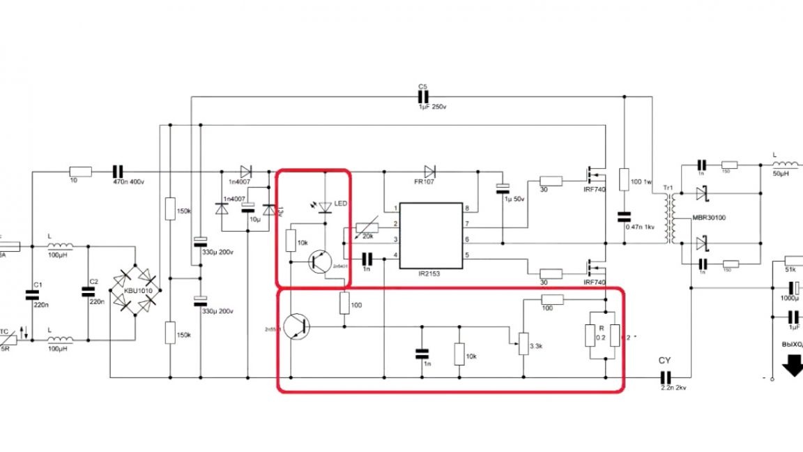
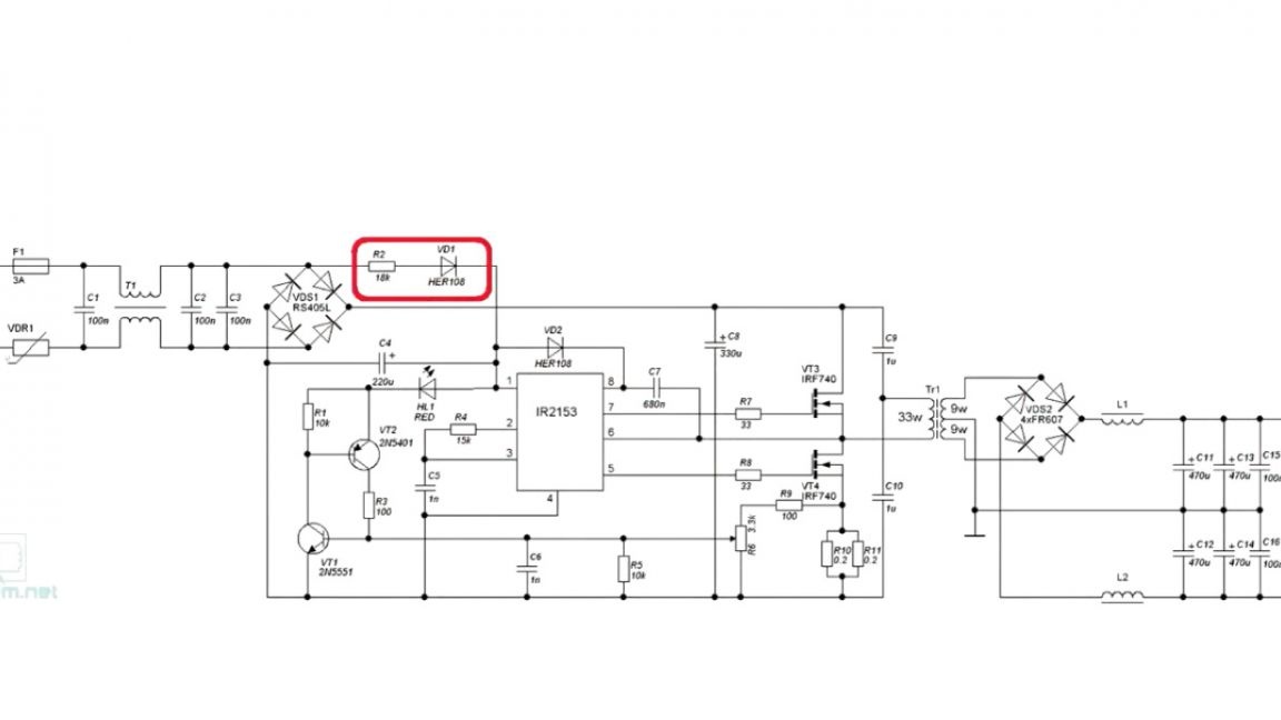
But after tests on the layout, it turned out that there was too little space to install the transformer and therefore the circuit had to be increased by 1 cm, this gave extra space on which the author installed protection. If it is not needed, then you can simply put jumpers in place of the shunt and not install the components marked in red.
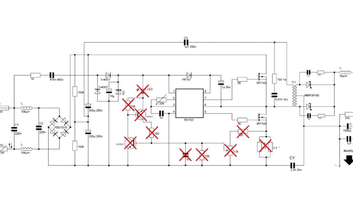
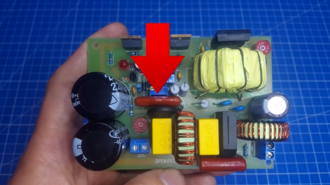
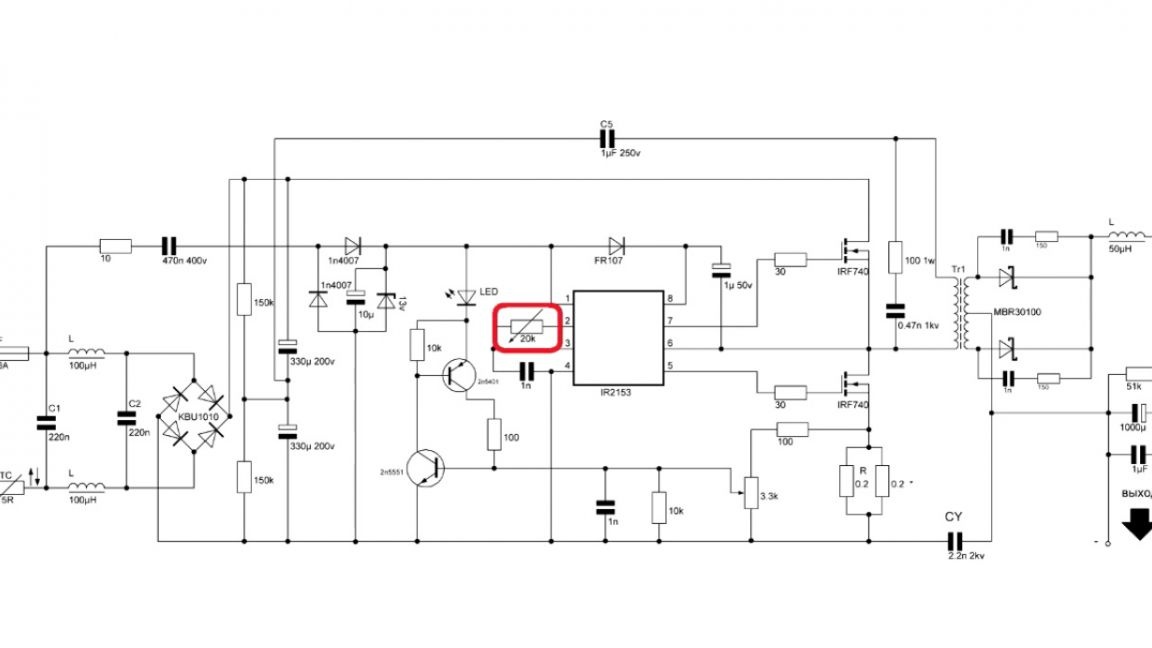
The protection current is regulated using this tuning resistor:
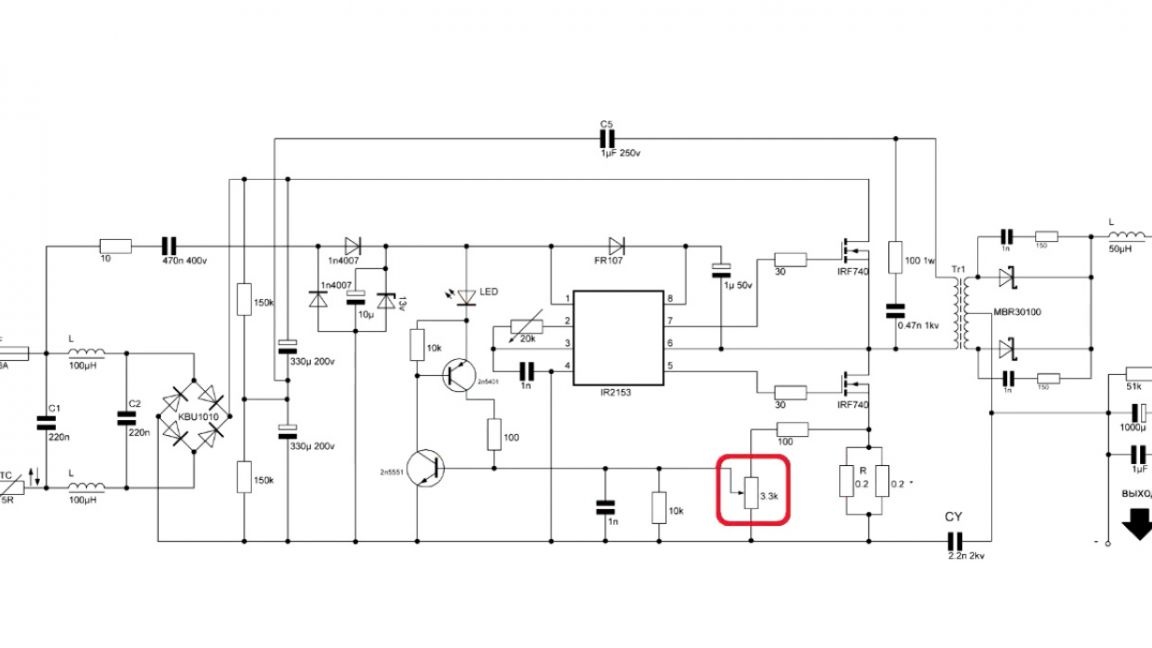
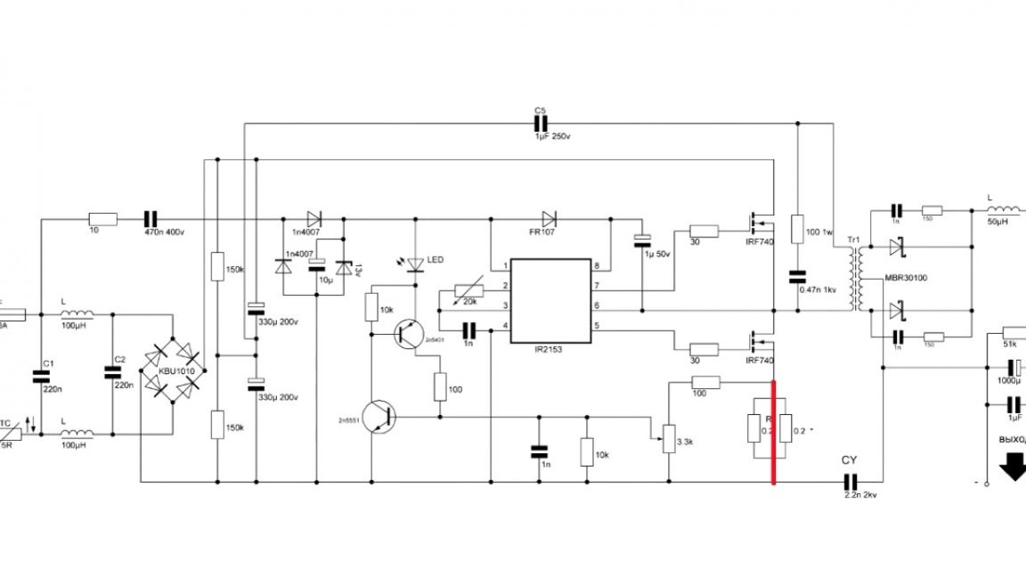
The values of the shunt resistors vary depending on the maximum output power. The more power, the less resistance is needed. For example, for power below 150 watts, 0.3 ohm resistors are needed. If the power is 300 W, then we need 0.2 Ohm resistors, well, at 500 W and above we put resistors with a resistance of 0.1 Ohms.
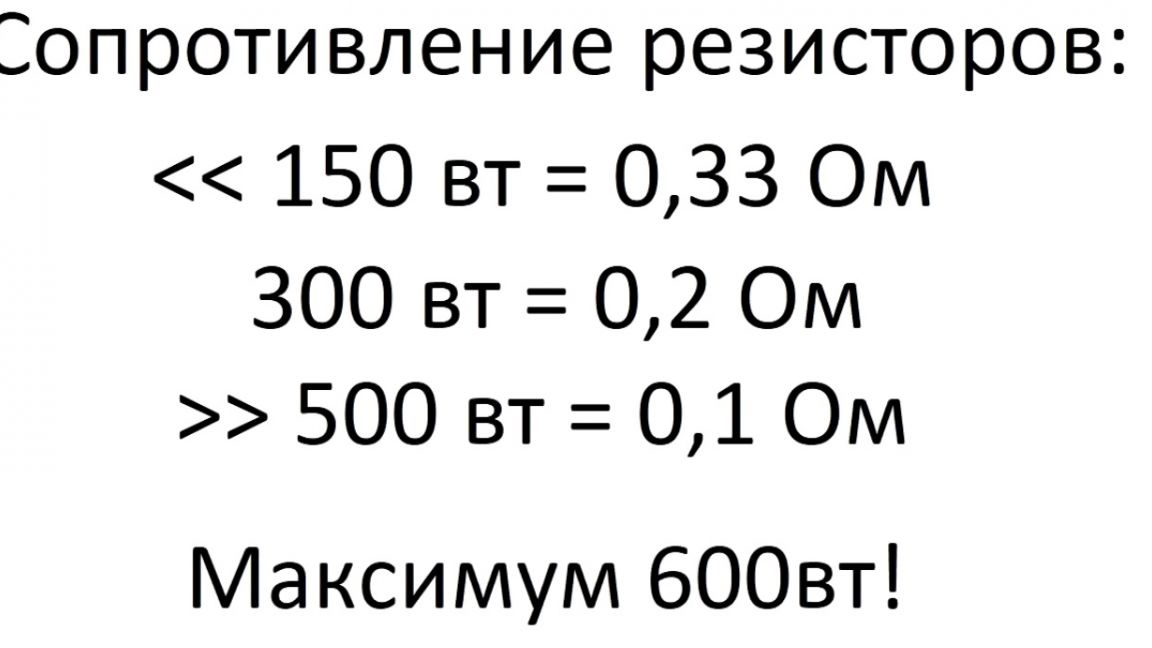
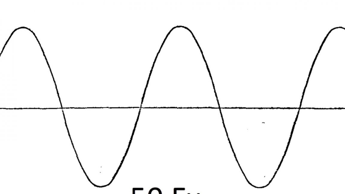
This unit should not be assembled with power above 600 watts, and also a few words about the protection work. She's hiccuping here. The starting frequency is 50 Hz, this is because the power is taken from the alternating current, therefore, the latch is reset at the mains frequency.
If you need a snap-in option, then in this case, the IR2153 microcircuit needs to be powered continuously, or rather, from high-voltage capacitors. The output voltage of this circuit will be removed from the half-wave rectifier.
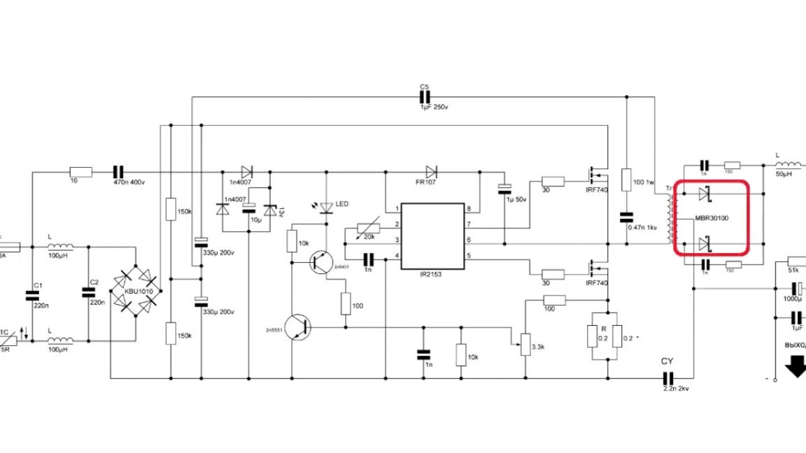
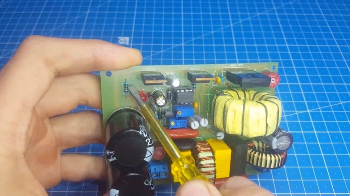
The main diode will be the Schottky diode in the TO-247 package, select the current for your transformer.
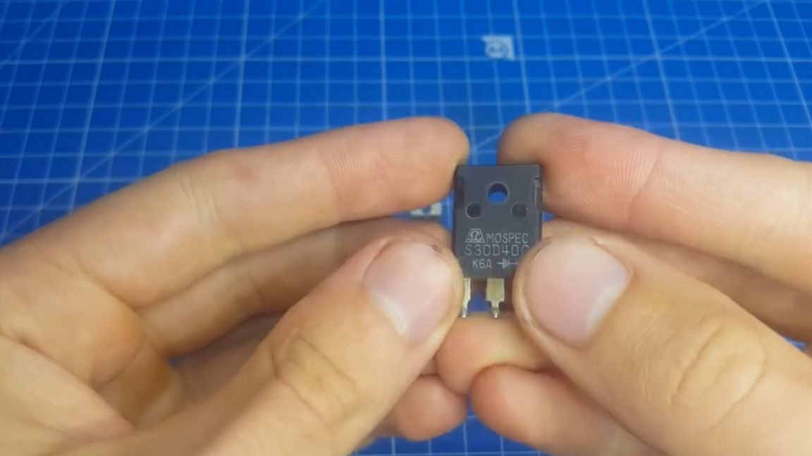
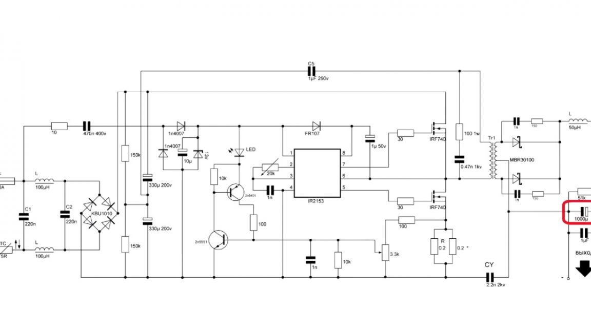
If there is no desire to take a large case, then in the Layout program it is easy to change it to TO-220. At the output, there is a capacitor of 1000 μF, it is enough for all currents, since at high frequencies the capacitance can be set less than for a 50 Hz rectifier.
It is also necessary to note such auxiliary elements as snubber in the transformer harness;
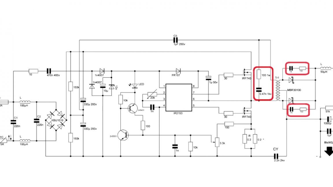
smoothing capacitors;
and also a Y-capacitor between the high and low ground, which dampens the noise on the output winding of the power supply.
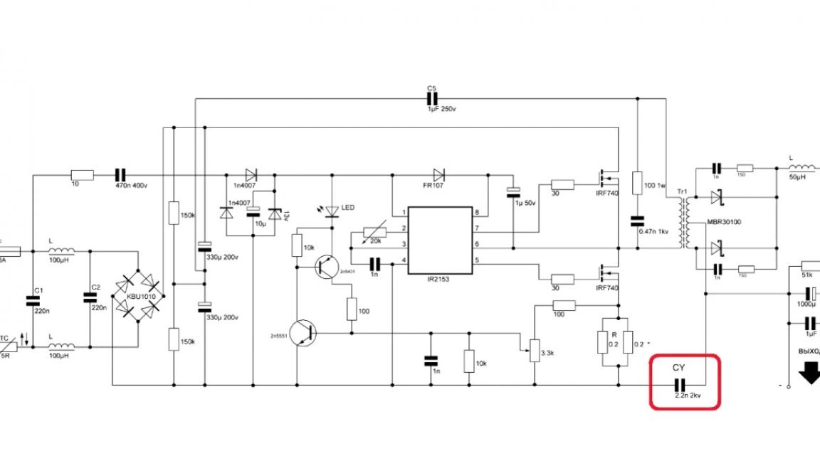
About these capacitors there is an excellent video on YouTube (the author attached a link in the description under his video (the SOURCE link at the end of the article)).
You can not skip the frequency-setting part of the circuit.
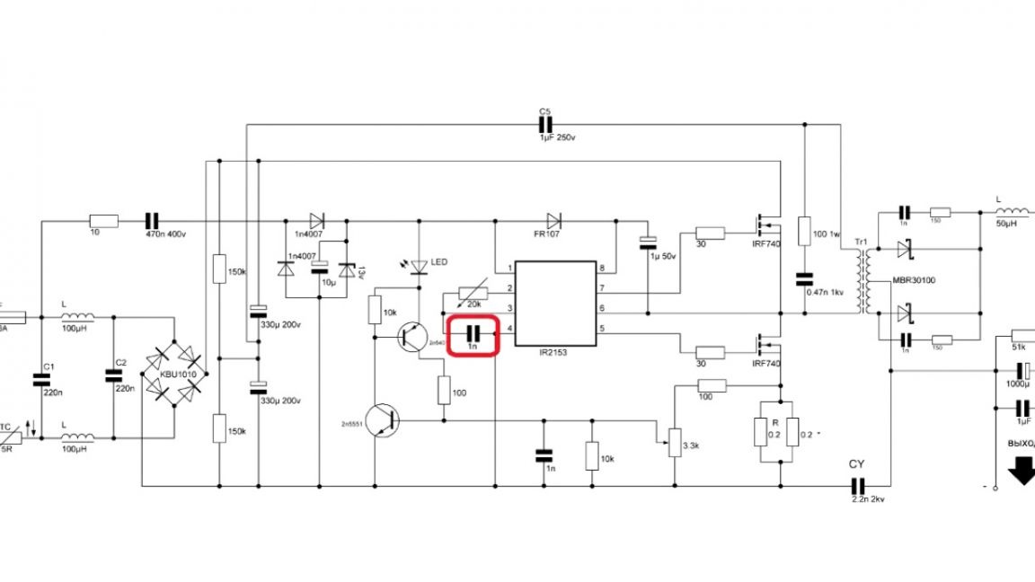
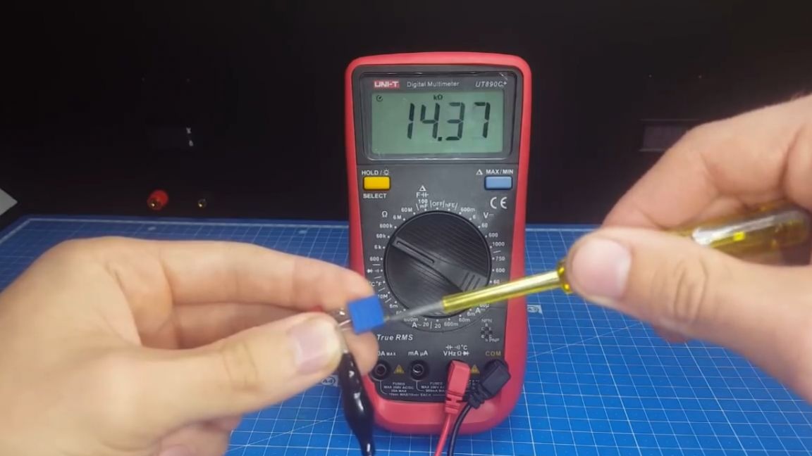
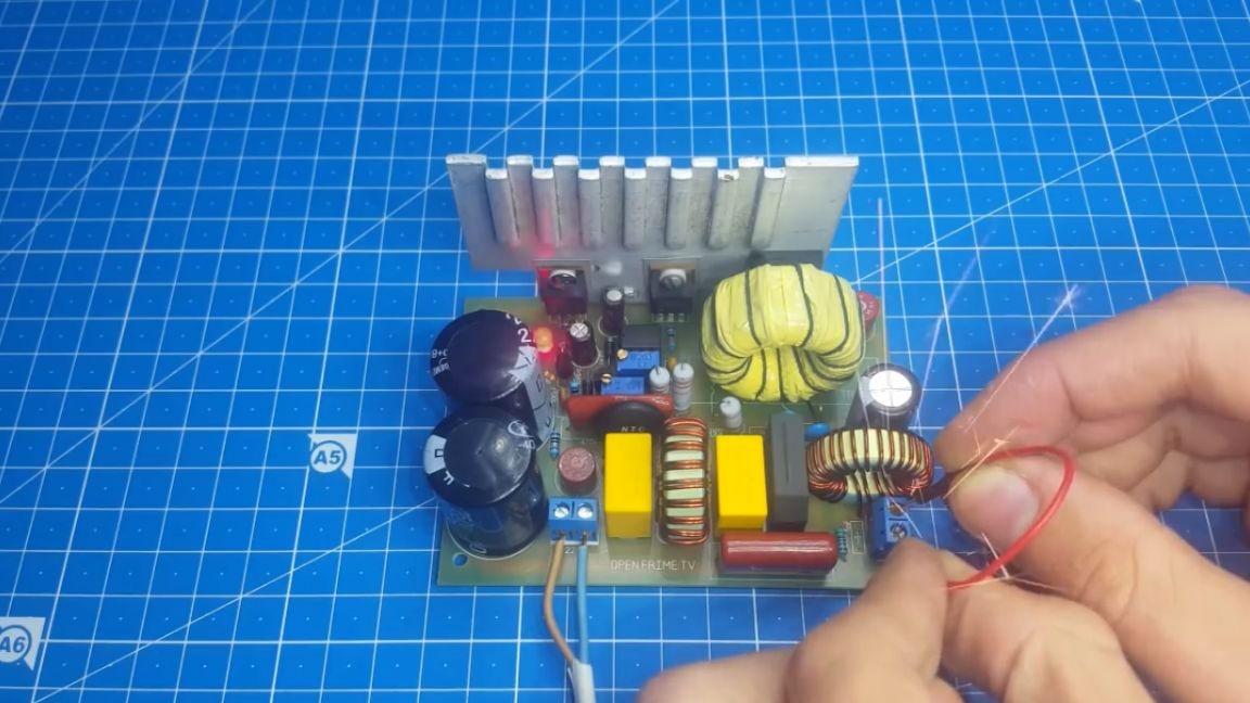
This is a 1 nF capacitor, the author does not recommend changing its rating, but he set the resistor of the master part to tuning, there were reasons for this. The first one is the exact selection of the desired resistor, and the second is a small adjustment of the output voltage using the frequency. And now a small example, let's say you are making a transformer and see that at a frequency of 50 kHz the output voltage is 26V, and you need 24V. By changing the frequency, you can find a value at which the required 24V is output. When installing this resistor, we use a multimeter. We clamp the contacts into crocodiles and rotating the handle of the resistor, we achieve the desired resistance.
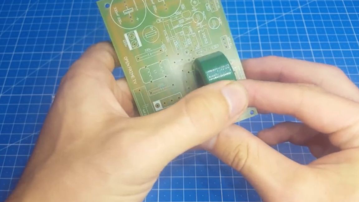
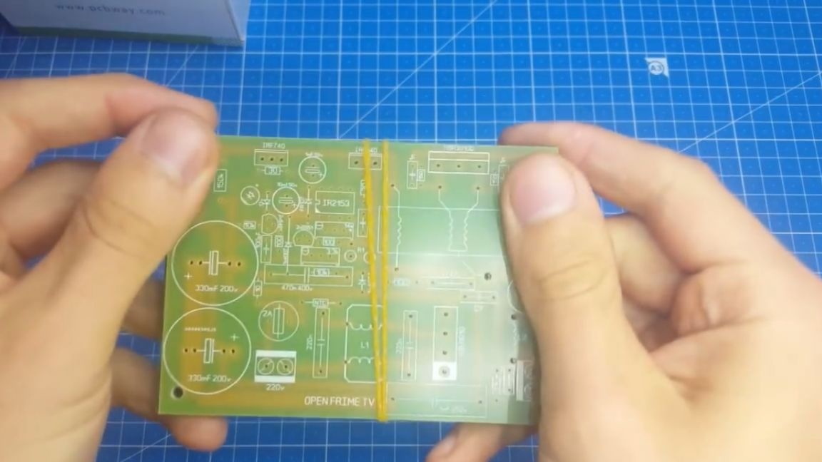
Now you can see the 2nd breadboard on which tests were carried out. They are very similar, but the protection board is slightly larger.

The author made mock-ups in order to order the manufacture of this board in China with a calm soul. In the description under the original video of the author, you will find an archive with this board, circuit and signet. There will be in the two shawls and the first and second options, so you can download and repeat this project.
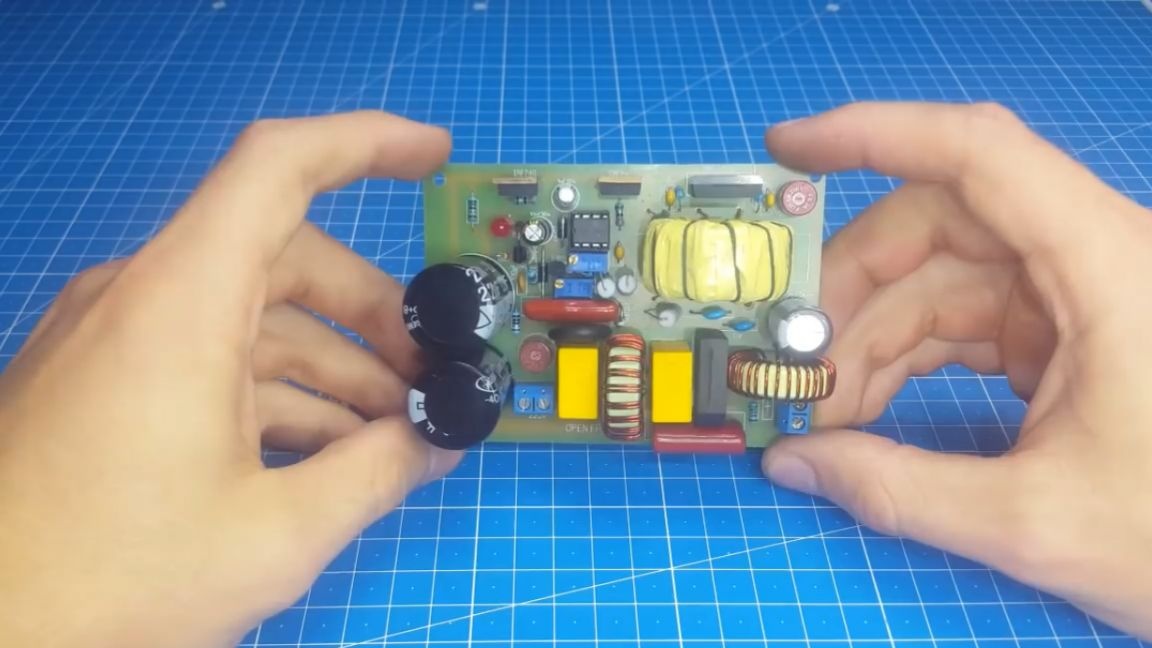
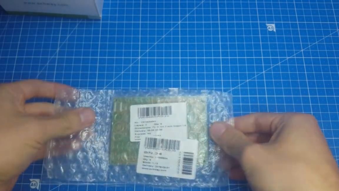
After the order, the author was looking forward to the board, and now they have arrived. We open the package, the boards are reasonably well packed - you won’t get into trouble. Visually inspect them, everything seems to be fine, and immediately proceed to solder the board.
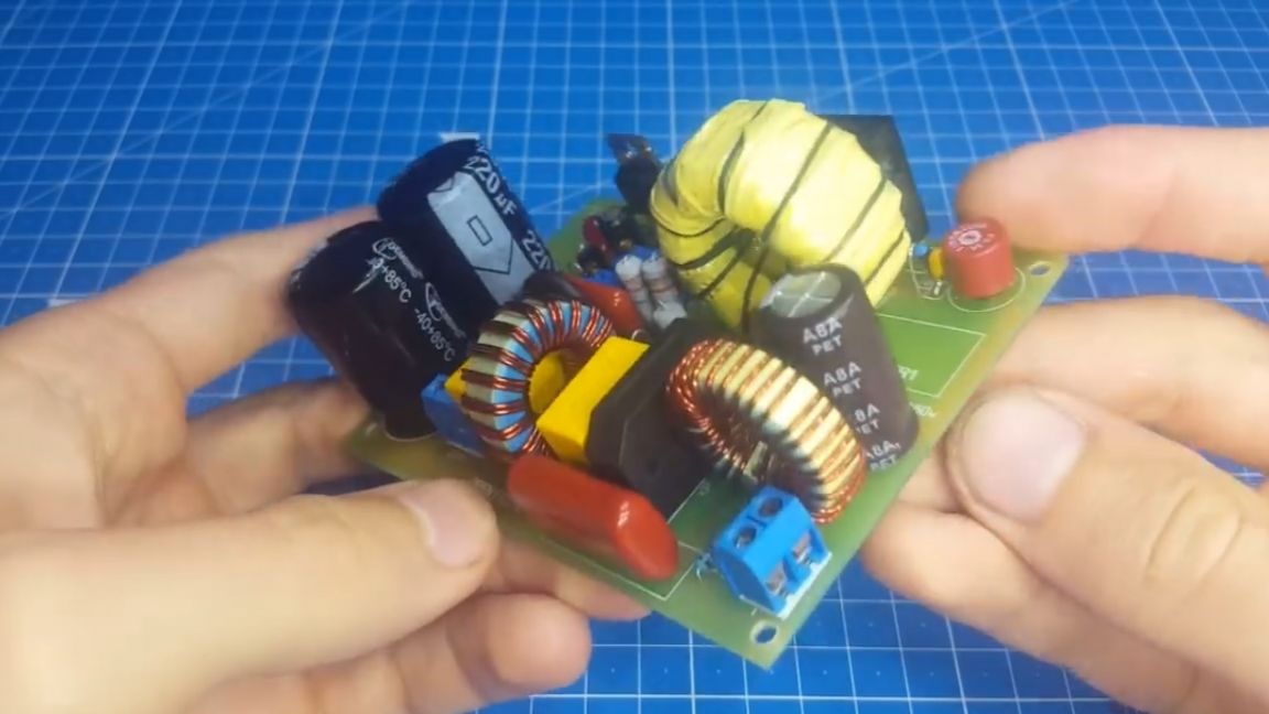
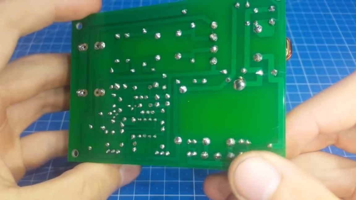
And now she is ready. Everything looks that way. Now let's quickly go through the main elements not previously mentioned. First of all, these are fuses. There are 2 of them, on the high and low side. The author applied such round ones, because their sizes are very modest.

Next we see the filter capacitors.
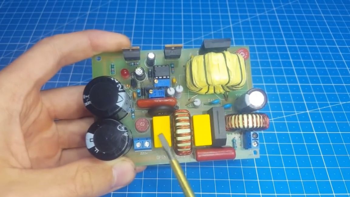
You can get them from the old computer power supply. The author wound the inductor on the t-9052 ring, 10 turns with a wire of 0.8 mm 2 core, but you can use the inductor from the same computer power supply.
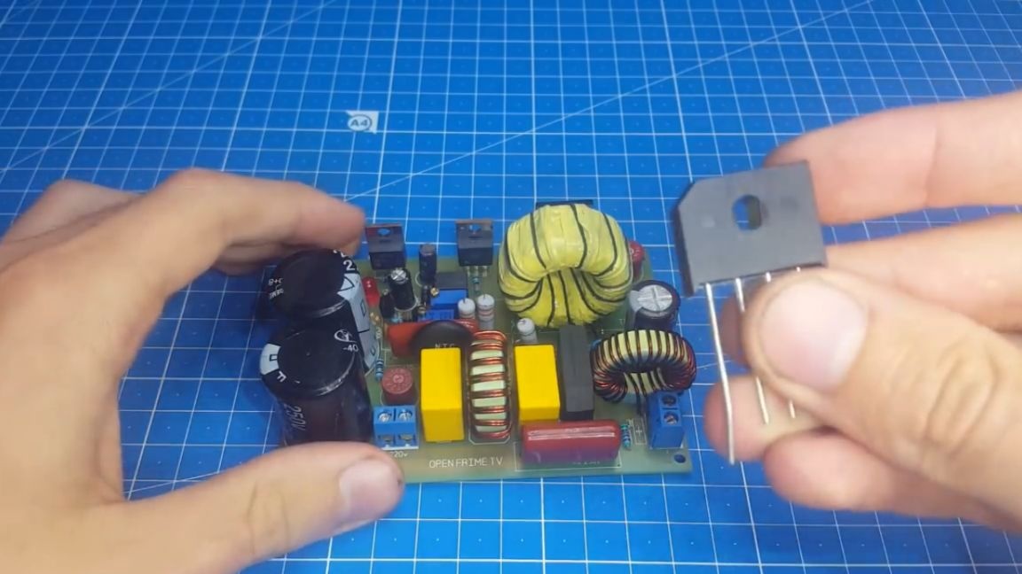
Diode bridge - any, with a current of at least 10 A.
There are also 2 resistors on the board for discharging capacitance, one on the high side and the other on the low.
Well, the throttle remains on the low side, we wind it 8-10 turns on the same core as the network one.
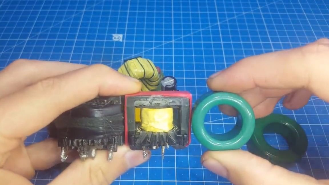
As you can see, this board is designed for toroidal cores, since they are of the same size with the W-shaped, have a large overall power.
It is time to test the device. So far, the main advice is to make the first inclusion through a 40 W bulb.
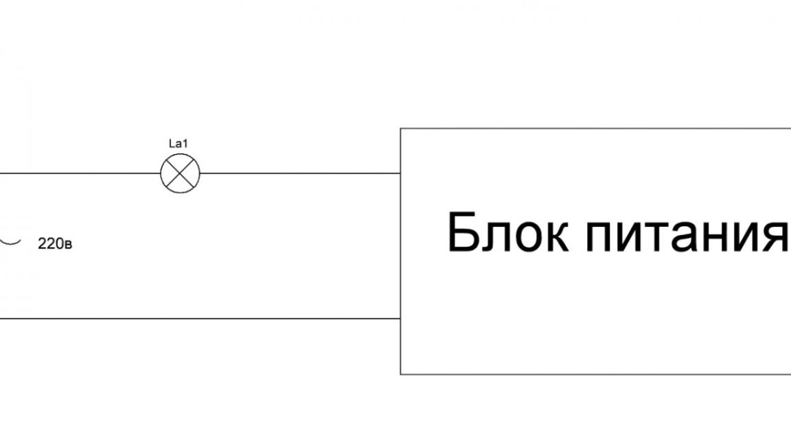
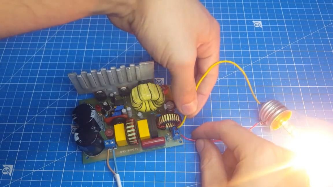
If everything works as usual, the lamp can be thrown back. Check the circuit for work. As you can see, the output voltage is present. Let's check how the protection reacts.Crossing your fingers and closing your eyes, short the conclusions of the secondary.
As you can see, the protection worked, everything is fine, now you can load the block harder. For this we use our e load. Connect 2 multimeters to monitor current and voltage. We begin to gradually raise the current.
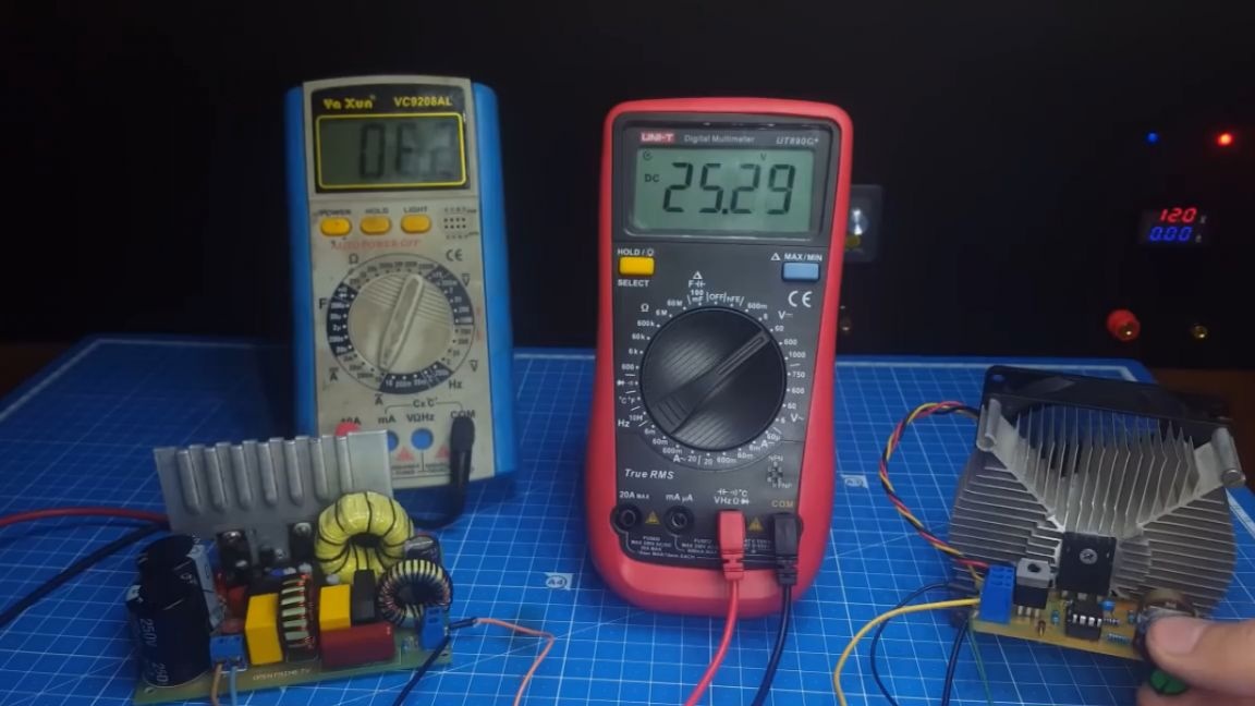
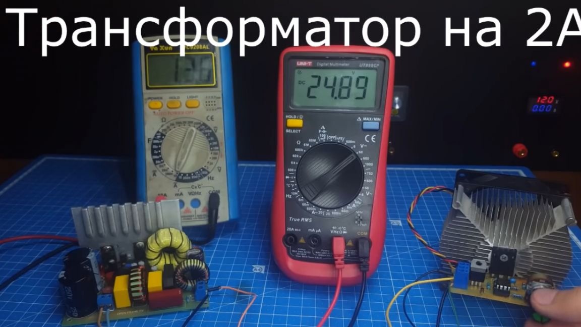
As we see at a load of 2A, the voltage dipped slightly. If you put a more powerful transformer, then the drawdown will decrease, but it will still be, since this unit has no feedback, so it is preferable to use it for less capricious circuits.

And that’s all. Thank you for attention. See you soon!
Video: