
Now, together with the author of the YouTube channel Radio-Lab, we will collect a battery for 4 banks from separate 18650 Li-ion batteries with a protection board, which is also BMS.
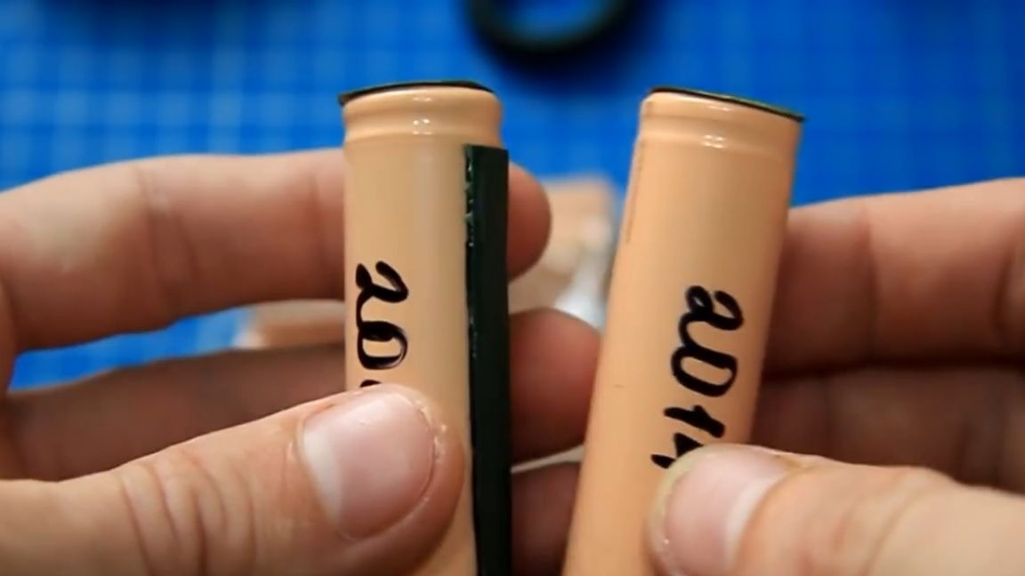
For future projects of the author, such a battery will be needed. On the Internet, he bought 8 of these Li-ion disassembled batteries, like the company Sanyo.

Banks used, but drove on the charger - everything is fine, they will still work, the capacity is about 2100 mAh. We will use the protection card here, one of those not expensive with a built-in balancer (which is important), there are protection against overcharge and overdischarge.
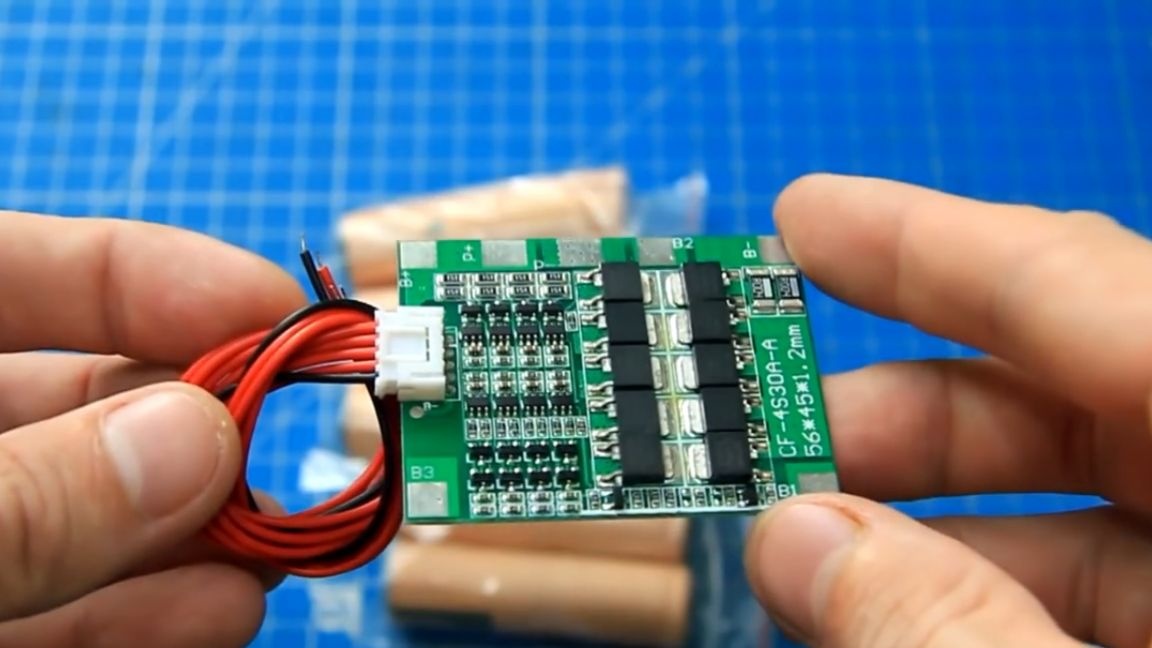
The discharge current is declared up to 30A, for most of this tasks with a margin. To increase the capacity, we will solder two batteries for each can in parallel. But you can’t do this right away, you need to level the battery levels so that they ruin each other. The easiest way is to fully charge all the batteries and then you can connect them in parallel. For charging, for example, you can use such a simple charger based on the popular headscarf.
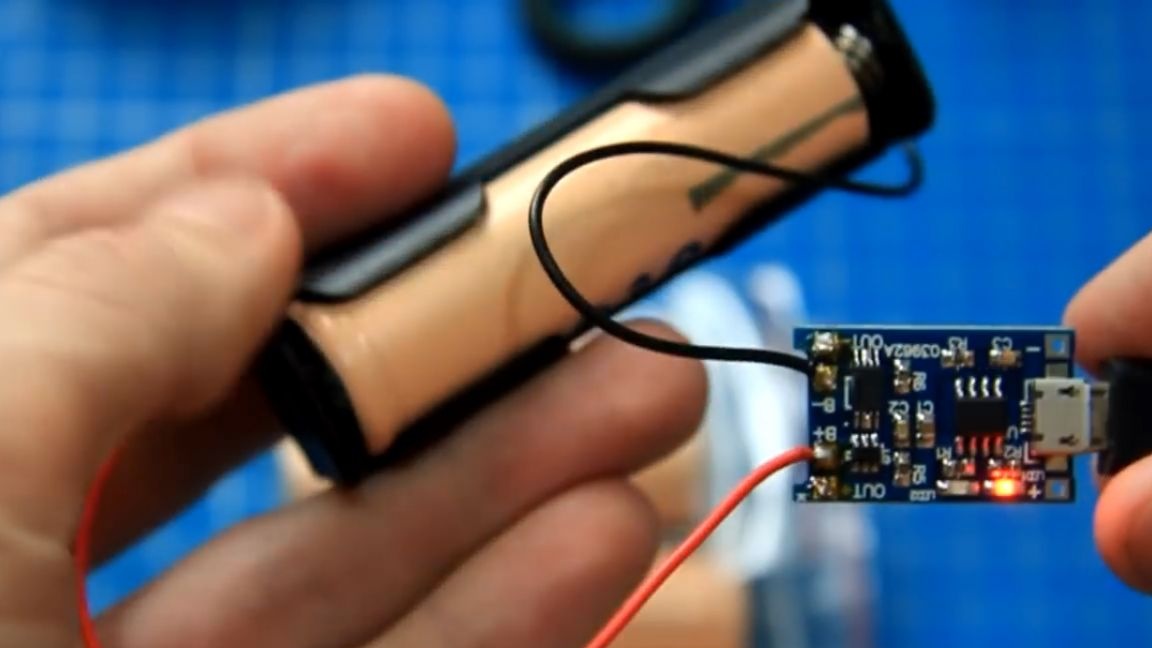
Charged batteries can already be soldered in parallel, you can solder such batteries, but you need to do this quickly.
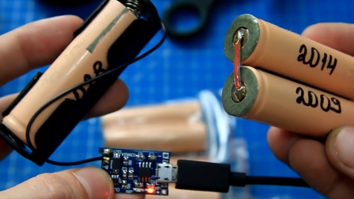
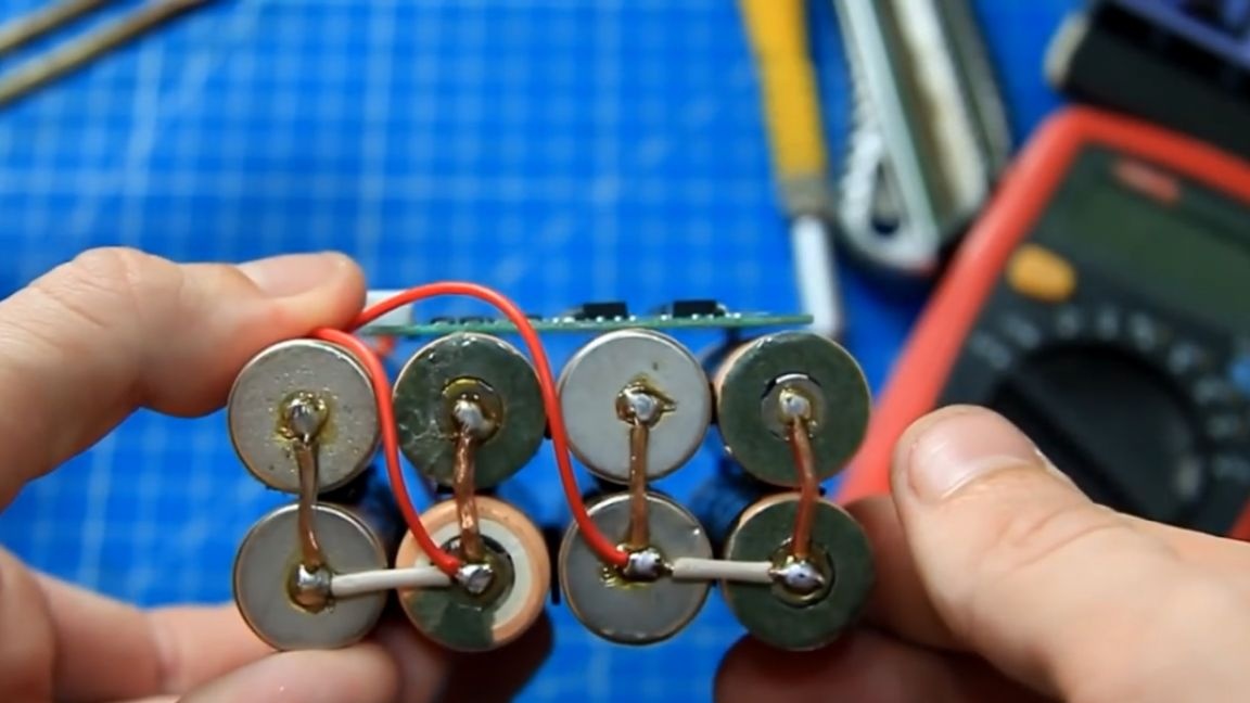
We will connect the batteries with each other using double-sided adhesive tape.
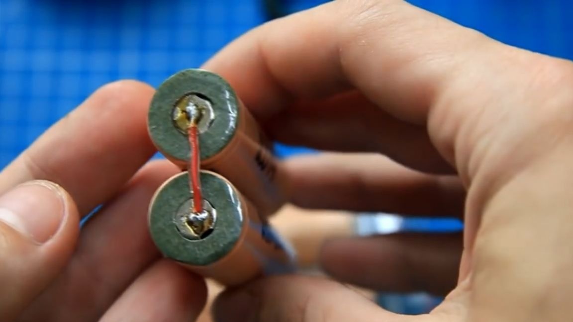
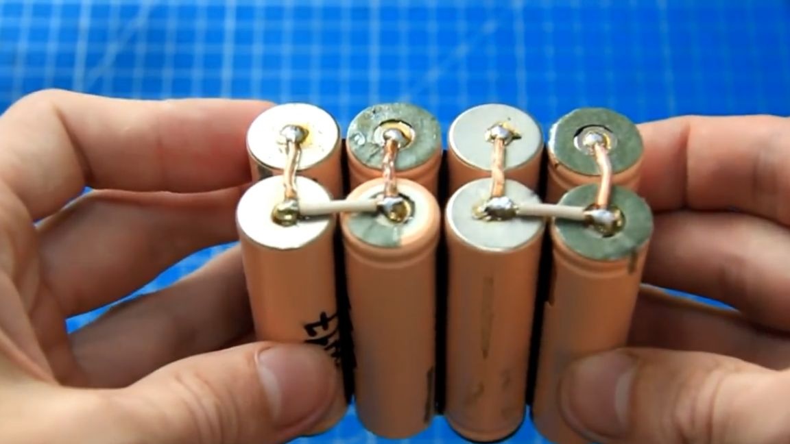
After that, we solder the batteries in pairs and get 4 separate banks for the future 4S battery. By connecting the batteries in parallel, we get an increase in capacity. For such assemblies, it is advisable to take batteries in one batch.
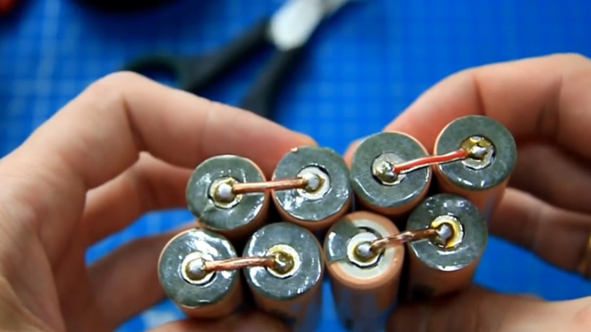
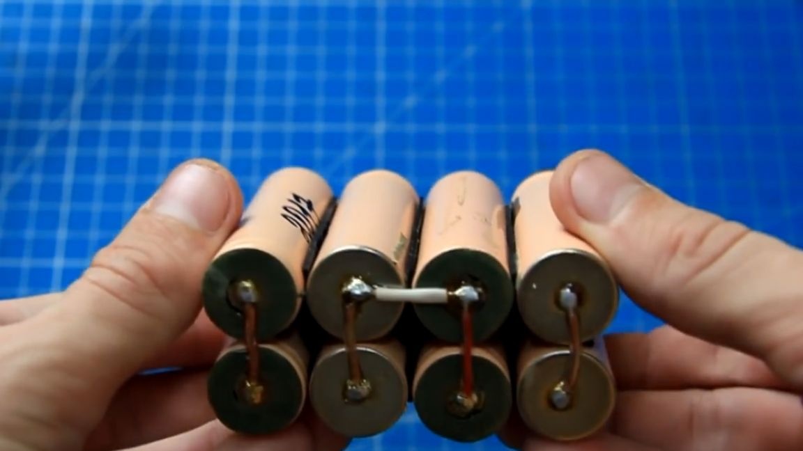
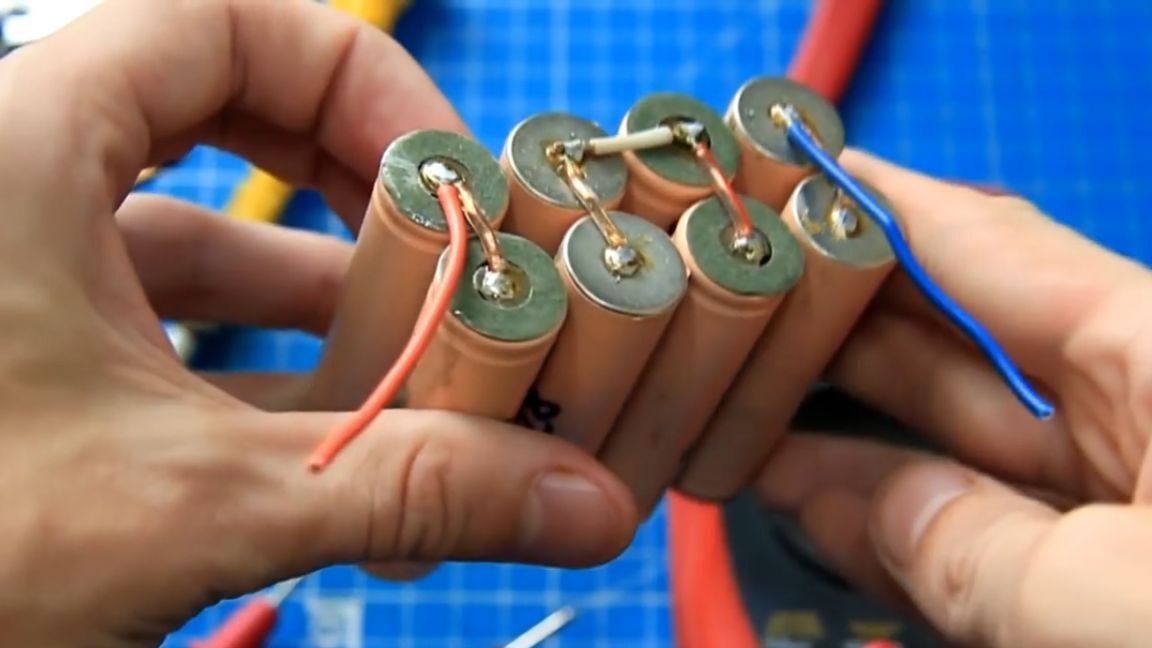
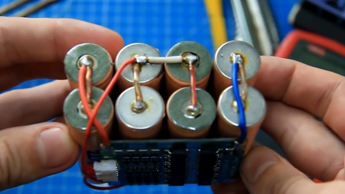
Then we connect the batteries so that we get an alternating chain of plus (+) and minus (-).
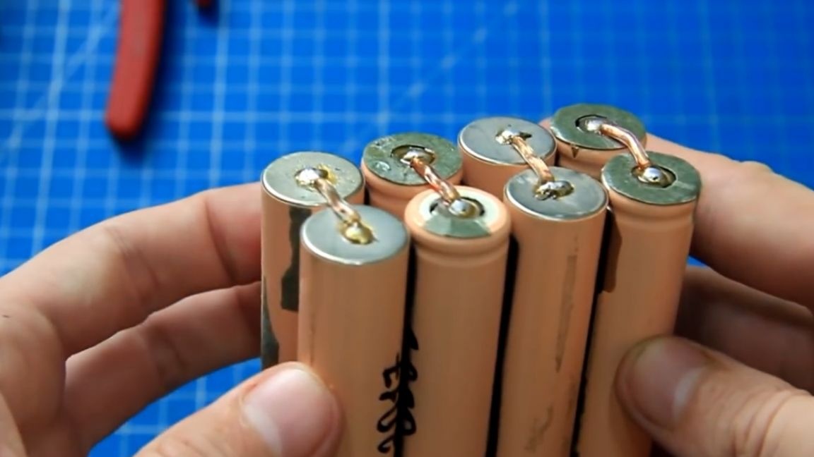
After that, we connect all the banks in series and as a result we get one battery.
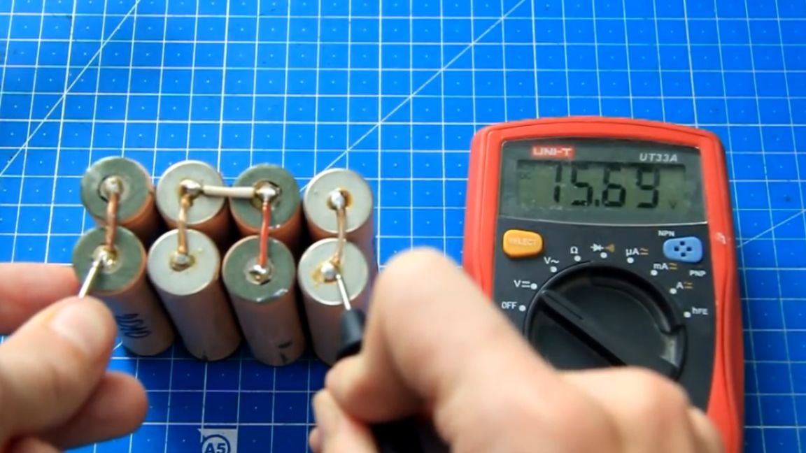
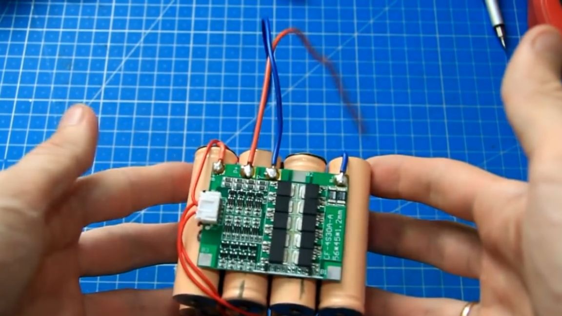
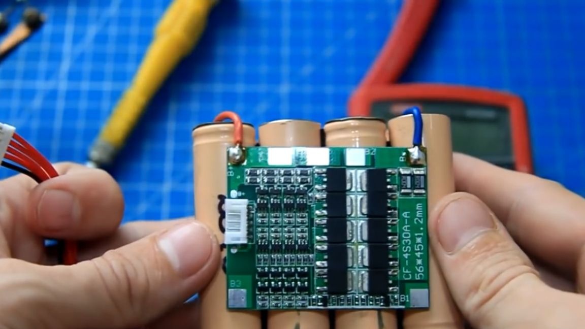
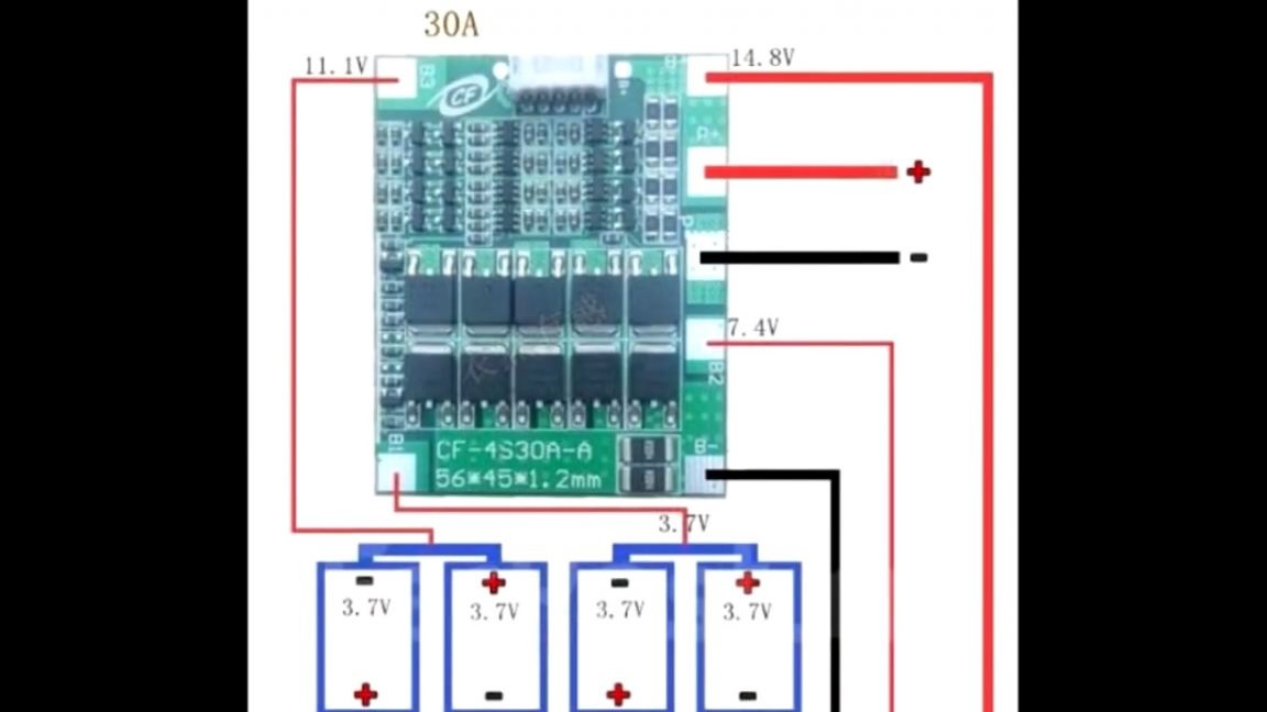
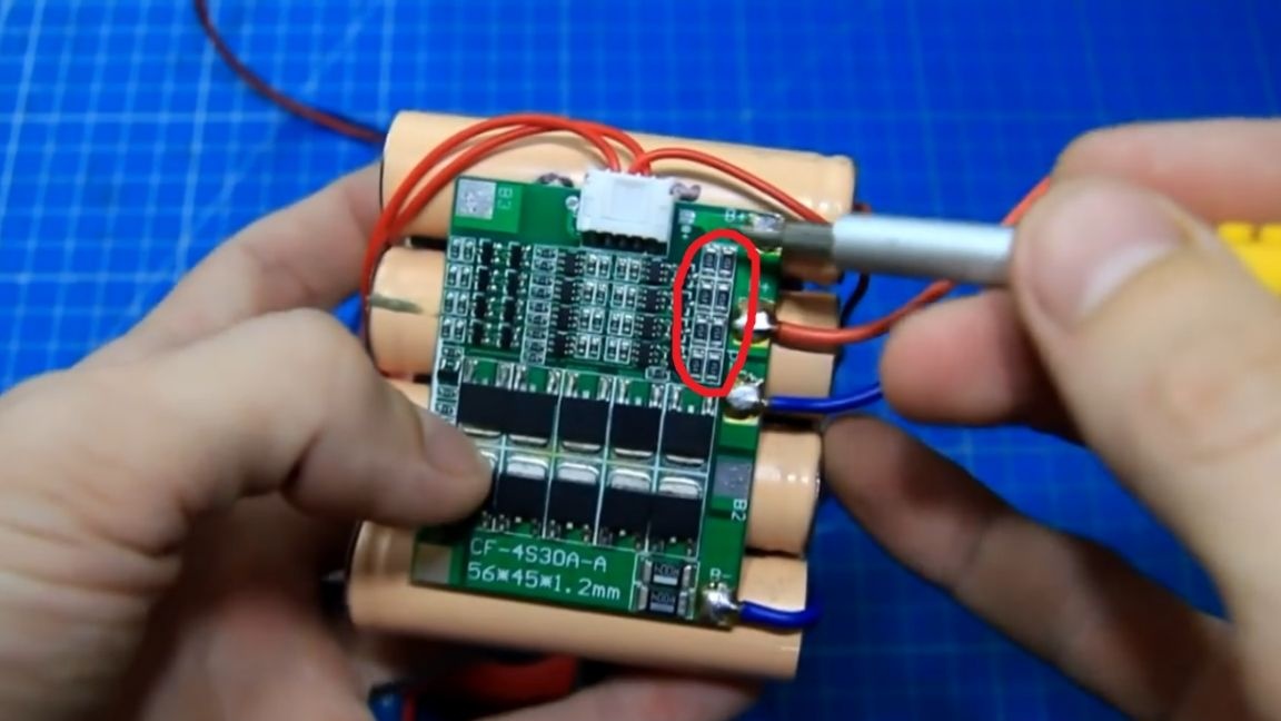
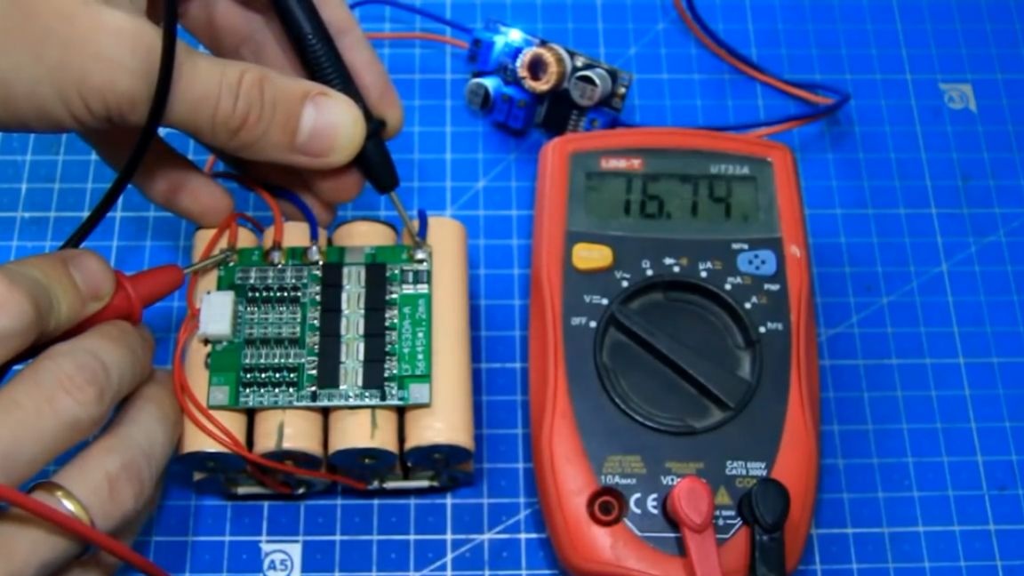
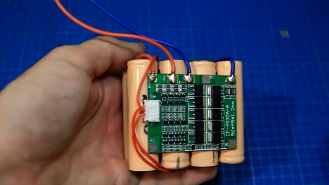
The total voltage of the entire assembly so far is 15.69 V, but for this battery to work for a long time, it needs to be protected. For this purpose, we will use just such a BMS board.
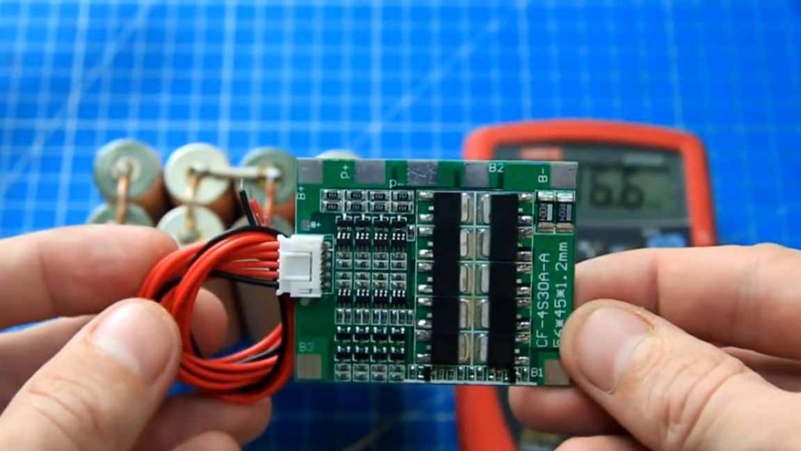
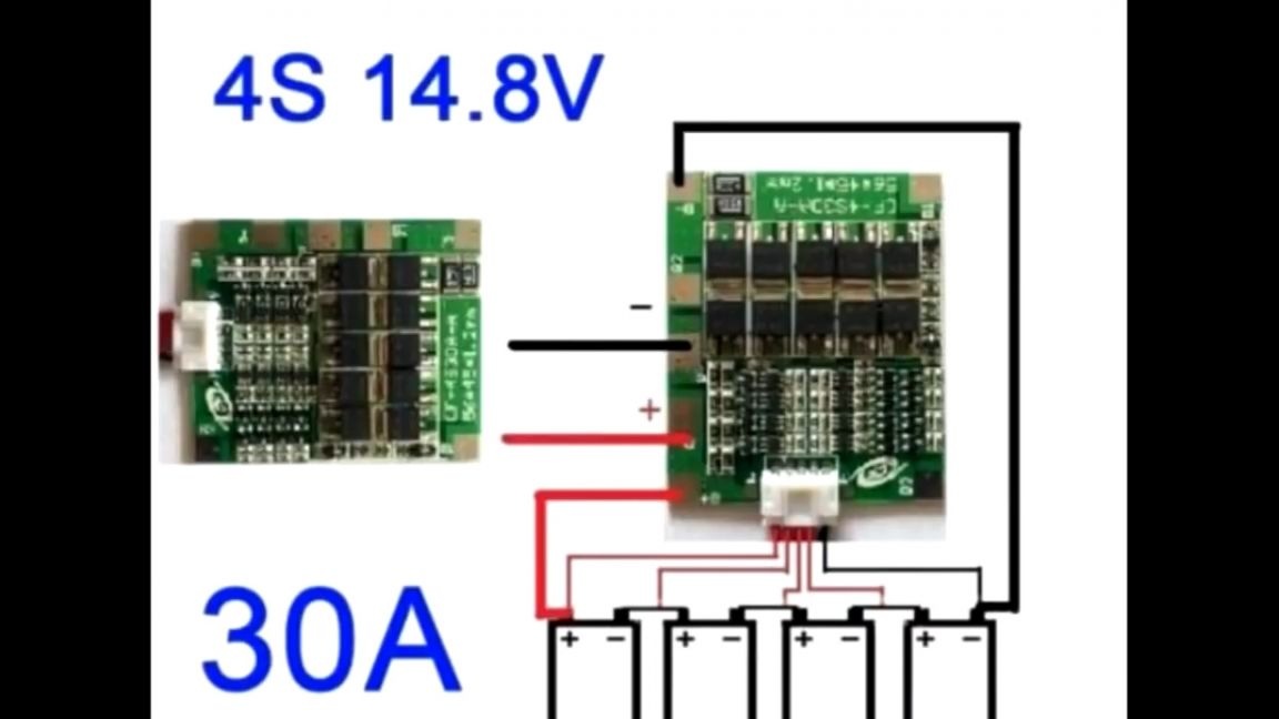
How to connect it correctly can be seen in the figure above. First of all, we will connect power + and - assemblies. We solder the power + and - to the battery and then, observing the polarity, we solder these wires to the B + and B- contacts on the board, everything is conveniently done.
Now it is very important to correctly connect the wires for balancing. The author pulled out two extreme wires of the balancer connector (they are power + and -), they are already connected to the main tracks on the BMS board and in this case are not needed.
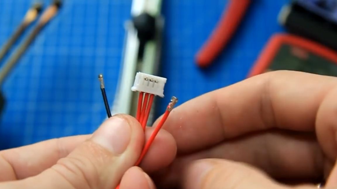
We connect the balancing connector and according to the scheme we solder the balancing wires to the battery, the main thing is not to rush anything.
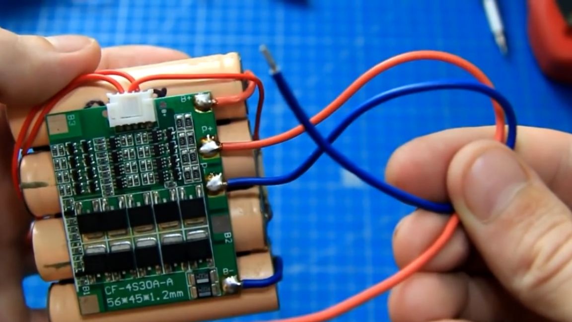
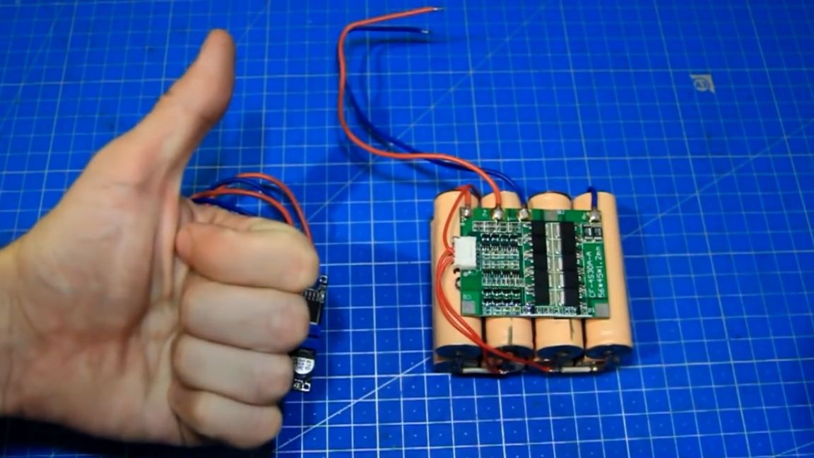
If this is done incorrectly, then the balancer parts will begin to warm up and may fly off or burn out. As a result, we got such an already protected battery. Now in case of overcharging and overcharging (which is important for lithium), the board will simply disconnect the load and the battery will remain operational. There is also protection against short circuits.
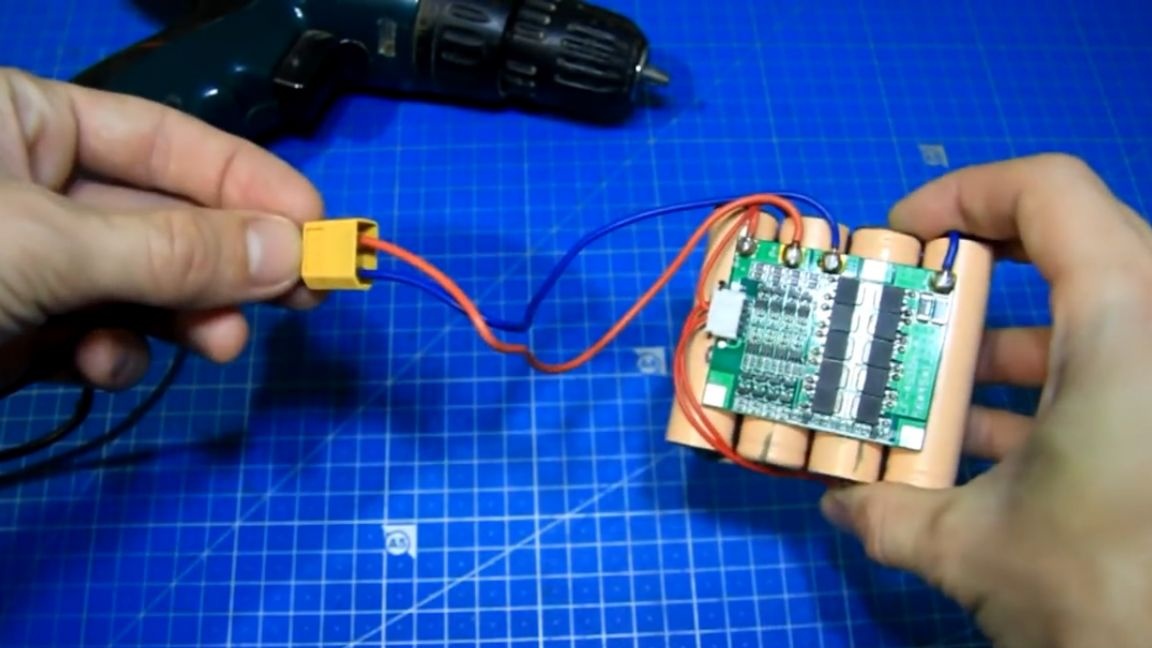
We solder wires to the P + and P- contacts, through which our battery will be charged and discharged.
And now, the battery is assembled, it seems to be normal. Then you can try to charge it. To do this, use a special power supply with charging function for 4S Li-ion batteries. But the author decided to use a conventional 19V power supply from a laptop.
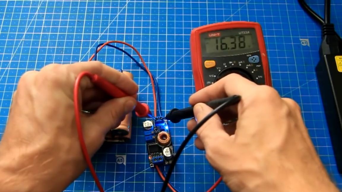
You cannot connect it directly to the battery, you need to set the charging voltage and limit the charging current, and the BMS board does not know how to do this and works approximately like a relay for turning it on and off. In order for the battery to charge correctly, we will use just such an additional scarf for the DC-DC converter.
It has the necessary algorithm for charging Li-ion batteries, with voltage settings and limiting the charge current. The voltage of one charged battery is 4.2V, multiply by 4 and get the voltage of the entire charged assembly. According to the calculations, this is 16.8V, but for the normal operation of the BMS board we take the value of 4.25V and set the value at the output of the converter slightly higher.
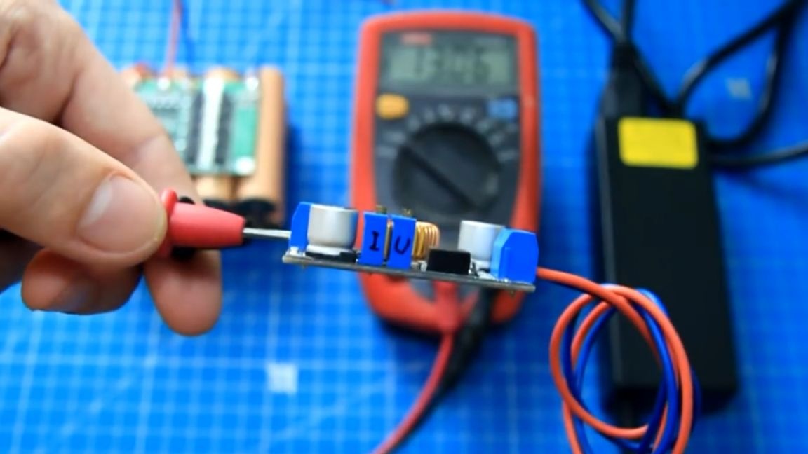
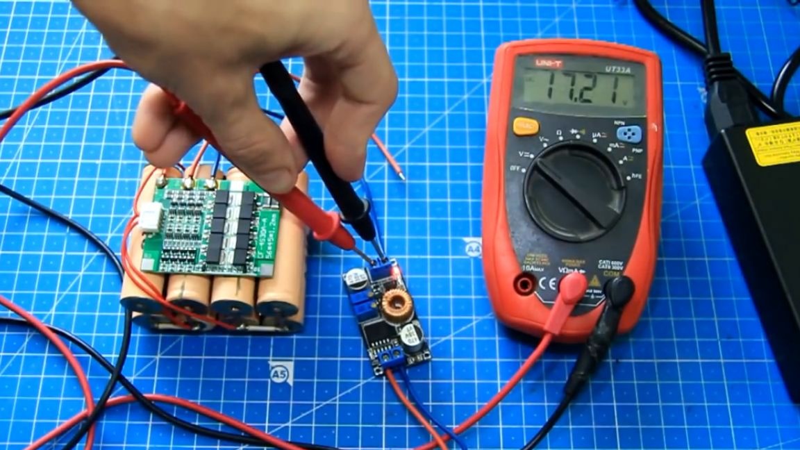
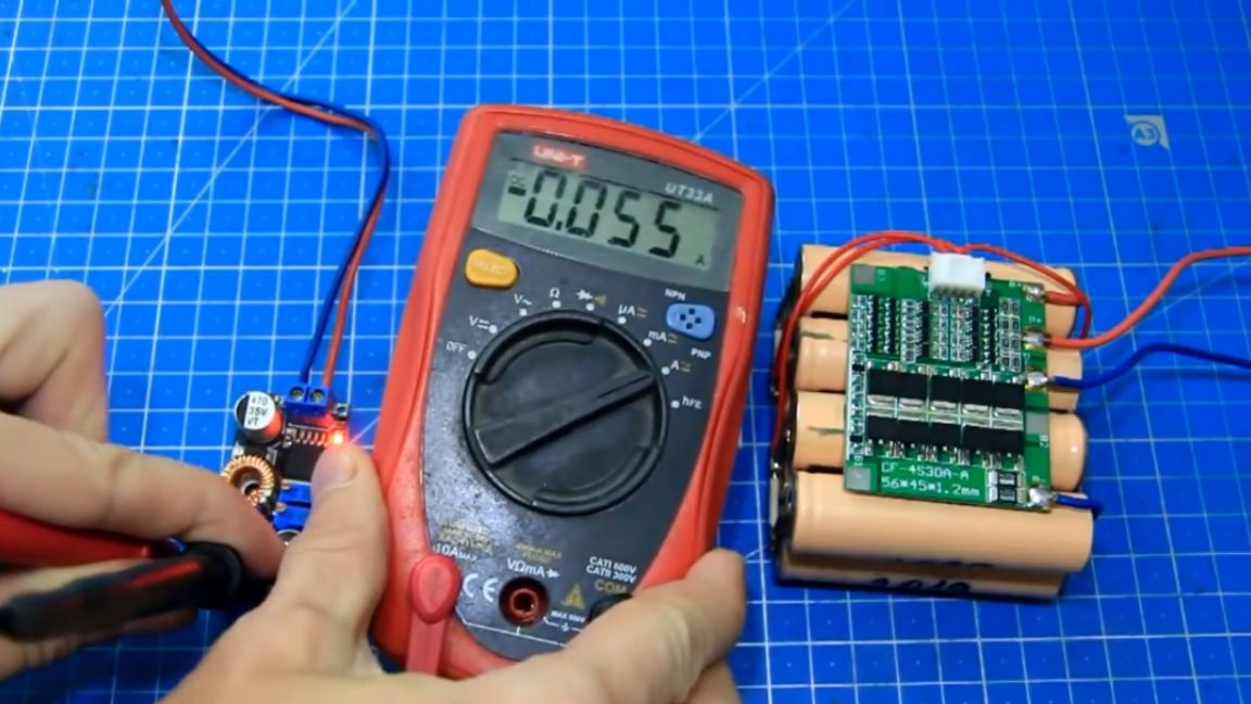
For convenience, the author signed where the voltage is regulated, and where is the current. We set the voltage to 17.2V. The charging current is set to about 55mA, because the voltage of the cans is different and they need to be balanced correctly.
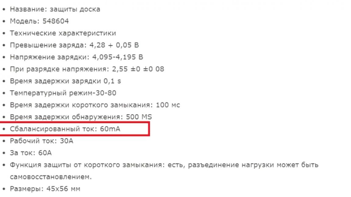
The balancing current for this board is indicated in the description and is 60mA.
During balancing, these 8 resistors start to warm up:
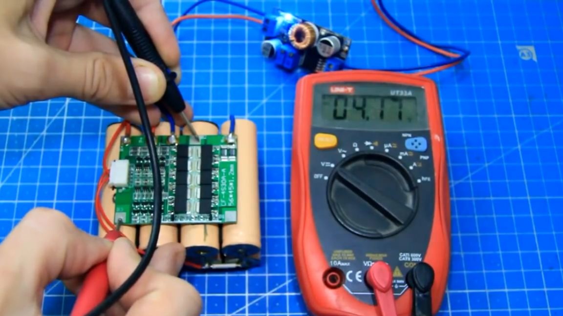
With a high charging current, the balancer may not have time to convert the excess charging energy into heat and normally balance the banks. We measure the voltage of each can and you can see that they are different.
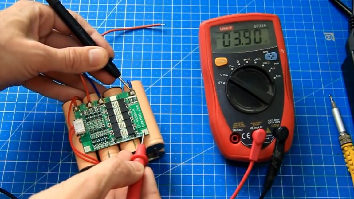
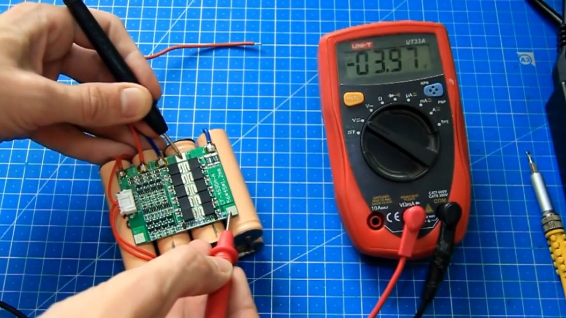
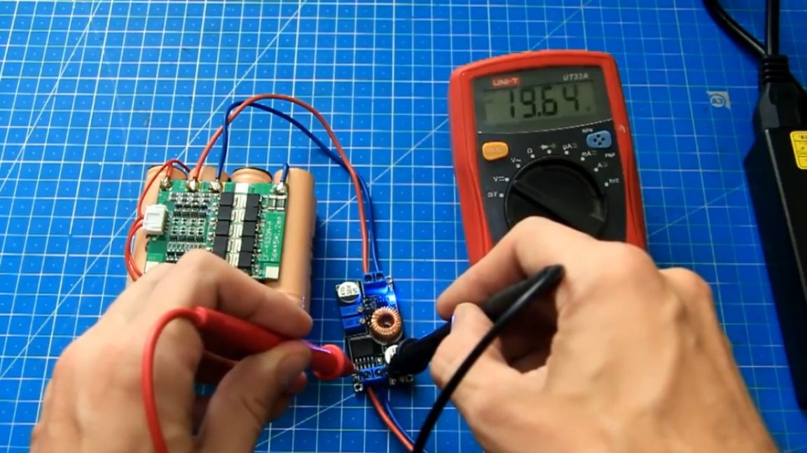
They must be balanced, that is, recharge those that are lower in voltage level so that everything is the same on all banks. Without balancing, some banks will be undercharged, and the entire assembly will not work fully. Now, after all the settings, you can connect the board of the step-down DC-DC converter to the battery and start the charging process. For convenience, the author signed where + and where -. We connect everything and the blue LED lights up, that is, there is a current limit, only 55mA that were previously configured, although the laptop's power supply gives more than 4A.
The input voltage is 19.6V, and the output of the converter will gradually increase to the level of the charged battery and at the end the blue LED will turn off, the red light will turn on and the BMS board will turn off the battery.
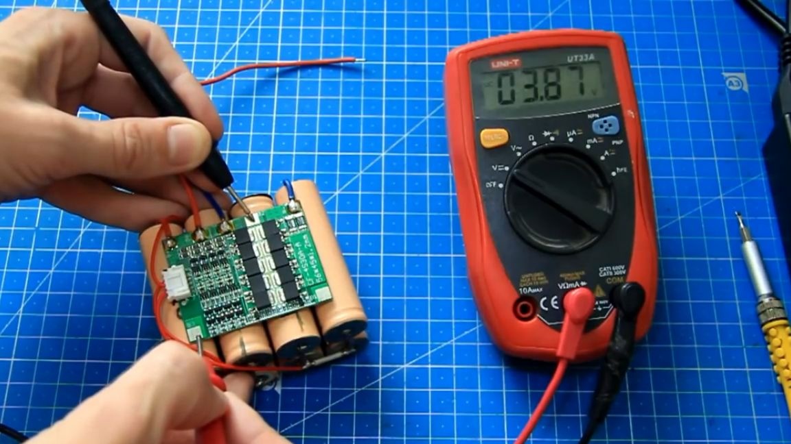
After a few hours, we check the voltage levels on each bank.
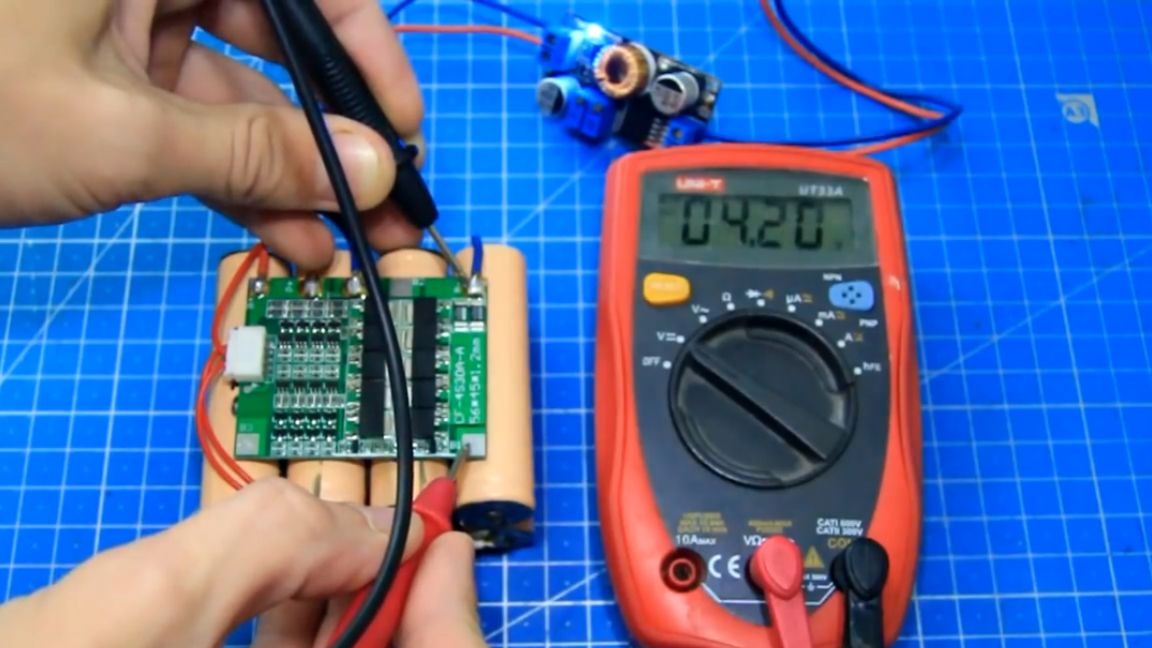
You can see that they are aligned and are approximately 4.2V, the battery is almost charged and balanced. Everything works.
It is advisable to make the first cycle of charging the battery low current, and then you can set the current higher, because usually the spread on banks is not large and the balancer manages to equalize the stresses. After two cycles, the author set the charge current to 2A and all the banks were charged equally, now this battery can be used to power different devices. For the test we will connect a screwdriver.
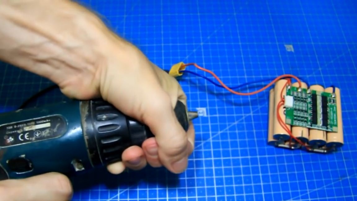
The screwdriver works, the battery does not go away in defense and holds the load. The screwdriver is old, at the 1st speed the author could not stop him, and at the 2nd speed he managed to stop him with his hand. Now let's check the protection against short circuits.
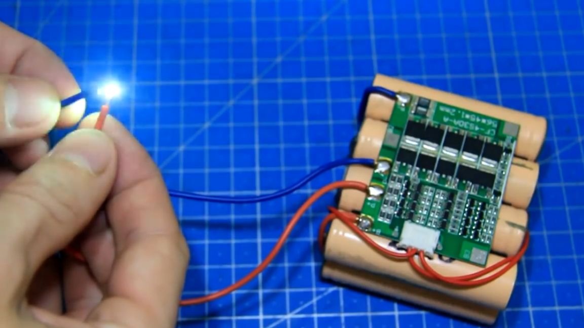
There is protection. And when there is no short, the board goes out of protection and is ready to power the devices further. Here we have assembled such a battery today and figured out how to charge it.Nevertheless, a small balancing current on this BMS board can be considered a minus, but this is not scary. In the future, this battery will definitely come in handy.
I hope it was interesting and useful. Try and most importantly do not rush. Useful links can be found in the description under the author’s video (link SOURCE). Thank you for attention. See you soon!
Video: