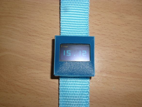
Good afternoon, today I want to share instructions on making watches based on Attiny 85 with an Oled display. The features of my watch are not limited to my watch. They can also be used as desktop, and you can also crush a digital temperature sensor.
For the manufacture of homemade we will need:
- Synthetic strap (any color)
- Velcro for clothes
- Digispark Attiny85
- Oled display with a resolution of 128x64, I2C
- ds18b20 - digital temperature sensor (optional)
- Resistor 4.7 Kom 0.25 W
- Arduino Digispark Attiny85 firmware board (ISP programmer)
- Sheet of thin plastic
- Colored wires
- Dupont 2.54 mm “female” connectors
- Buttons 2 pcs.
- Small circuit board or a small piece of circuit board
- Soldering iron, solder, rosin
- Thread, needle, scissors
- clerical knife
- Hot glue gun
- Hot glue
- Double sided tape
Step 1 Preparing the belt.
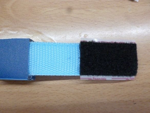
You can buy a strap at any needlework store. Choose a strap 25 mm wide. Any colour. We need a strip of about 50 cm. Fold our strap in half and sew along the edges. Then in the middle of the strap we make a slot, but only in one of the parts. Sew Velcro from the ends of the strap.
Put the thread with the needle to the side and take the soldering iron.
Step 2 Prepare the board and OLED display.
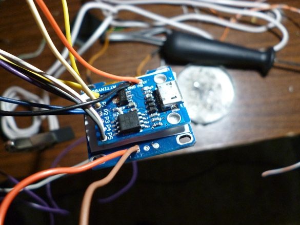
The “brain” of our watch will be the Digispark Attiny85 controller. They are available in several versions. You should buy a board with a Micro USB connector. Other versions of the board will not fit in the watch case.
If you bought a board with soldered contacts, you should first unsolder them. Then we take wires of different colors, we need 9 different colors. Cut off about 15 cm from each wire, strip it and solder to Attiny85. Immediately it is worth writing down which wire to which pin is soldered so as not to get confused later.
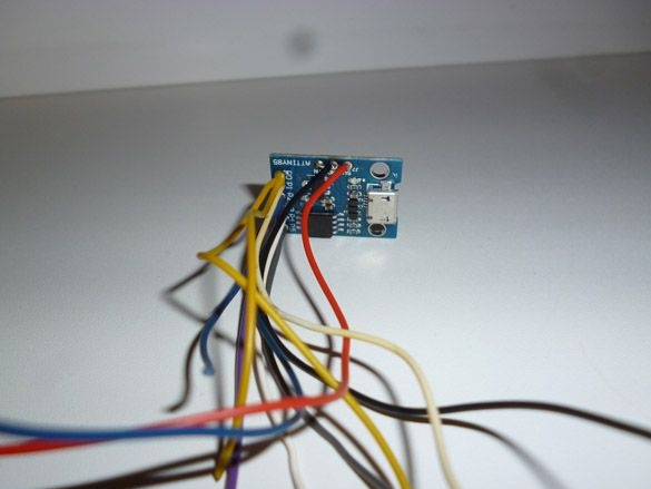
In my case, the wires by colors look like this:
PB0 MOSI - Yellow
PB1 MISO - Blue
PB2 CSK - Blue
PB3 - Purple
PB4 - White
PB5 NRES - Gray
GND - black
+5 - red
Vin - Orange
Your colors of the wires may vary, the main thing is to write them down.
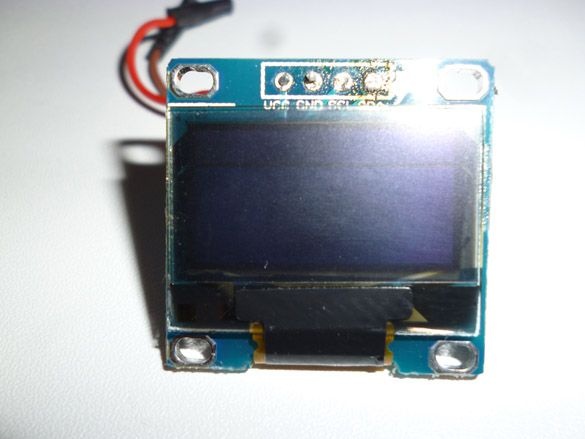
Let's move on to the screen. We will use an oled display. Screen resolution 128x64, works on the I2C bus. On sale there are screens of different colors: white, blue, blue with yellow. Be careful! The word “two-color” in the description and title of this screen indicates the presence of a strip of color different from the main one at the top of the screen, and not the ability to display two colors with this screen! All screens of this type display only one color, or at the top a strip of one color, at the bottom of another. I liked the blue screen, with a yellow bar at the top. Color does not play a special role, choose which one you like. As with Attiny85, if you bought a screen with soldered contacts, you should first unsolder them.
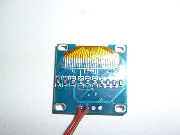
On the back of the screen you should solder small wires. It is better to use wires of the same colors as with Attiny85, so as not to confuse them later. In my case, I solder the yellow wire to the SDA of the screen, to the SCL - blue, GND - black, VCC - red.
On a double-sided tape we attach Attiny85 to the back of the Oled screen. Attiny85 should not go beyond the Oled screen board.
We solder Attiny85 and Oled together.
PB0 MOSI Attiny85 - Yellow - SDA Oled
PB2 CSK Attiny85 - Blue - SCL Oled
GND Attiny85 - Black - GND Oled
+5 Attiny85 - Red - VCC Oled
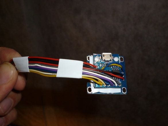
We collect all the wires in one row, so that we get a loop. We wind it with electrical tape in several places so that it does not fall apart.
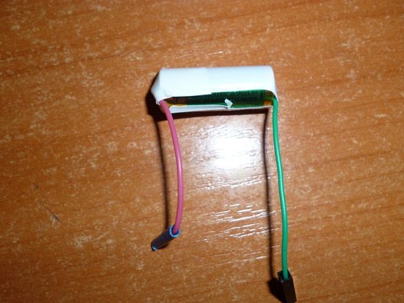
Go to the power of our watches. To do this, take a small lithium battery. Solder the wires to it.
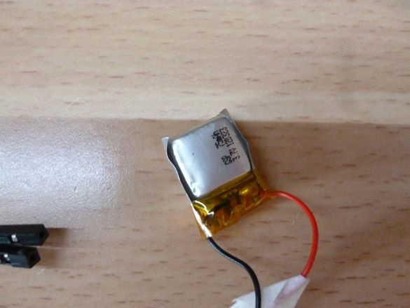
If there is no battery, a type A27 or A23 battery can be used.
We put the accumulator or the battery in the farthest corner of the pocket formed by the strap folded in half. If using a battery, provide a slot to replace it.
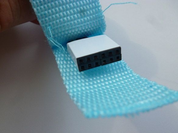
In the hole made in the middle of the strap, we stick our cable from the wires.
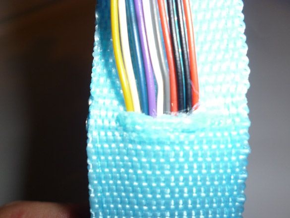
And we stretch them to the end of the strap, so that they stick out, and the watch is exactly above the slot, so that the slot closes for hours.
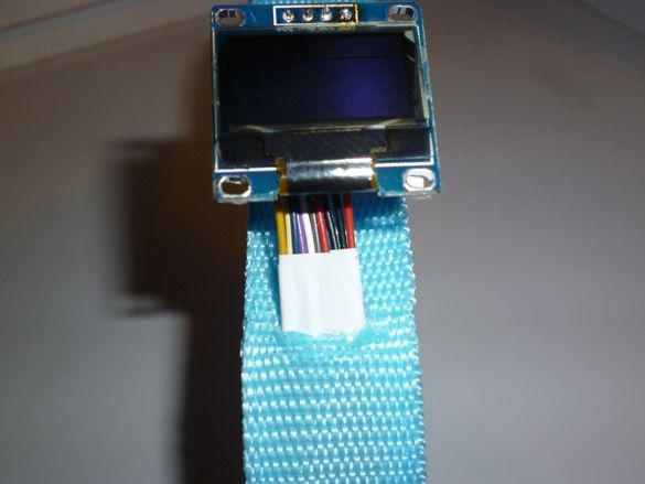
We cut off the excess ones and crimp all the wires of the Dupont 2.54 mm “mother” connectors. We insert it into plastic cases and wrap it with electrical tape, so that we get a neat connector, with all the Attiny85 leads. Here it’s also worth writing, or even better sketching, all the contacts of the resulting connector. GND Attiny, GND Oled and the minus of the battery can be immediately connected and crimped into one contact. For further filling in the sketch and connecting add-ons, it is most convenient to arrange the contacts as follows:
PB0 | PB1 | PB2 | PB5 | +5 ATTINY | GND ATTINY
PB3 | PB4 | VCC OLED | GND OLED | Vin ATTINY | + BAT
Now it's time to move on to the hull.
Step 3 Making the case.
For the body you will need thin plastic. It can be bought in the online store. Or you can buy a folder with a thick plastic cover in the stationery store and make a case out of the cover. On the plastic we mark the sweep of the watch. Solid lines are cut lines, dashed lines - bend.
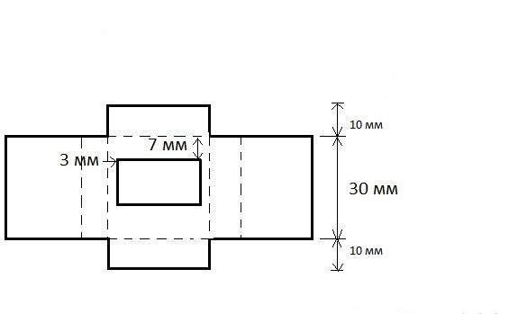
Using a clerical knife, carefully cut out the window in the middle. We bend all dotted lines. It should be like this:
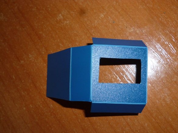
And on the flip side:
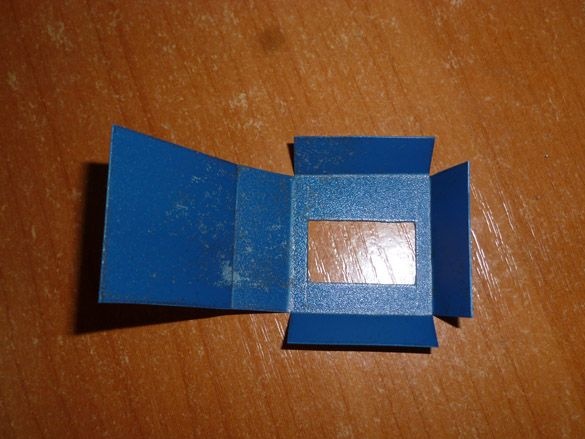
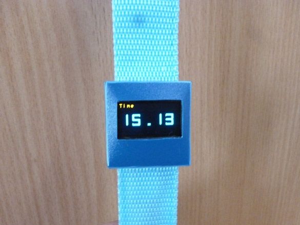
We put a slot on our screen, bend the edges and, using hot-melt adhesive, assemble our body. It is also worth gluing the case to the strap, preferably inside, so that the glue does not go out.
Step 4 Preparing the programming environment.
To work with the firmware (or sketch) we will use the Arduino IDE. Download the archive or installer from the official site Arduino IDE.
In addition, we need to add Attiny support to the Arduino IDE. To do this, run the Arduino IDE, then File - Settings - in the "Additional Boards Manager URLs" field, insert the link:
https://raw.githubusercontent.com/damellis/attiny/ide-1.6.x-boards-manager/package_damellis_attiny_index.jsonClick OK (you can enter several links separated by a comma in this field). Then go to Tools - Board - Boards Manager in the filter field, enter Attiny and select "attiny by David A. Mellis". Click Install and wait for the download to finish.
You will also need a library to work with the Oled screen. There are a lot of them, I liked it, and I recommend using TinyOzOLED. It is convenient, and most importantly, fits in memory:
In the future, you can expand the functionality of the watch by adding a temperature sensor. Add a library for this sensor immediately. OneWire Library.
Install these libraries. To do this, you can directly in the Arduino IDE programming environment, without unpacking the downloaded archives, select the Sketch - Connect Library menu. At the very top of the drop-down list, select the "Add .Zip library" item. In the dialog that appears, select the library that you want to add, in this case two downloaded ones. Now open the Sketch - Connect Library menu again. At the very bottom of the drop-down list you should see new libraries. From now on, libraries can be used in programs. After all this, restart the Arduino IDE. You can also simply unzip it to the “libraries” folder located in the folder with the Arduino IDE installed.
Step 5 Preparing the programmer.
Digispark Attiny85 can be programmed via the micro USB connector on the board using the Arduino IDE. However, you have to sacrifice 2 KB of 8 KB Flash memory for the bootloader.The clock sketch does not fit with the bootloader, so you must use the ISP programmer, thereby erasing the bootloader. If you don’t have an ISP programmer at hand (like mine), you can use the Arduino board instead. I will use Arduino Uno. But you can use any other board. So, we connect Arduino Uno to the computer. Launch Arduino IDE, open File - Examples - Arduino ISP. Select in the menu Tools - Board - Arduino Uno. We select the port to which it is connected, Arduino, and clicks download. The sketch starts with a hint on how to connect the Arduino to the programmable controller.
// 10: slave reset
// 11: MOSI
// 12: MISO
// 13: SCK
Scheme of connection to Digispark Attiny85:
Arduino UNO - Digispark Attiny85
D11 - P0
D12 - P1
D13 - P2
D10 - P5
Step 6 Prepare the wire for loading the sketch.
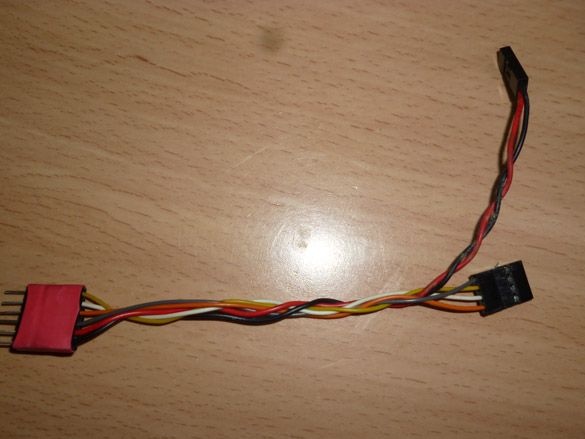
There are several options for the sketch, and just for the convenience of downloading, we will manufacture a wire connecting the Arduino Uno (as an ISP programmer) and our watch. Here I also recommend using colored wires that match the color that we have already used. On the one hand, there should be a block:
PB0 Yellow | PB1 Blue | PB2 Blue | PB5 Gray | +5 Red | GND Black
This block connects to the watch, at the top of the watch block.
On the other hand, there are two pads for connecting to the Arduino Uno:
Pin 10 Gray | Pin 11 Yellow | Pin 12 Blue | Pin 13 Blue
+5 Red | GND Black
It should look something like this:
Step 7 Firmware.
So, I wrote some sketch options for our watches. I will write later what are the differences and lay out everything. To fill the sketch, run the Arduino IDE, select the Tools menu, set the following parameters:
Board - Attiny 25/45/85
Processor - Attiny 85
Clock - internal 16
Select the serial port to which the ISP programmer or Arduino is connected as a programmer. Also, in the Tools - Programmer menu, select "Arduino as ISP". Now select Sketch - Download via the programmer. It remains to wait for the download to complete.
Step 8 Sketches.
The first option is a watch with a date. To set the time, you will need to connect buttons, something like this:
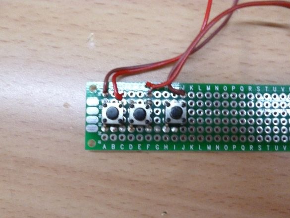
To pins PB1, PB3, PB4.
The second option is only a watch. To set the time you need to use USB-TTL.
And the third option, a desk clock with a date and a thermometer.
Step 9 Launch.
To start the clock, if you use a lithium battery, you need to install a jumper in the block between the contacts BAT, +5 and VCC. You can use a small piece of thin wire. If you have a battery, you will need two jumpers, put the first between BAT and Vin, the second - + 5 and VCC.