» Electronics » Arduino »Adjustable 18650 battery soldering iron with 5v 8W tip on ATmega8. Auto power off. Backlight Charge indication

Adjustable 18650 battery soldering iron with 5v 8W tip on ATmega8. Auto power off. Backlight Charge indication

Hello to all lovers of rosin smoke.
I want to introduce my homemade pretty easy job for me.

YouTube video. Rechargeable portable soldering iron:


The fact is that my work is connected with soldering, wires, plugs on such equipment for which a potential of 90 volts on the tip of a soldering iron can cause the product to “die” and from 30 to 500 tr gaps in the budget. Agree, it stimulates?)) And besides, everything happens in such a FIELD environment that, looking around you can see a plowed field, brush off raindrops from your face and rearrange boots with adhering dirt to dig for carrying to connect a soldering iron. All this made me think about an adjustable rechargeable soldering iron. From the pros, no need to ground, no wires, compact. Of the minuses, a small power (8 W) and an adapter is needed for periodic charging.

So the idea was born to make such a soldering iron yourself.

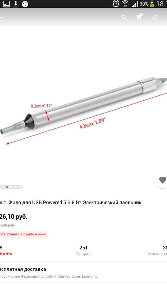
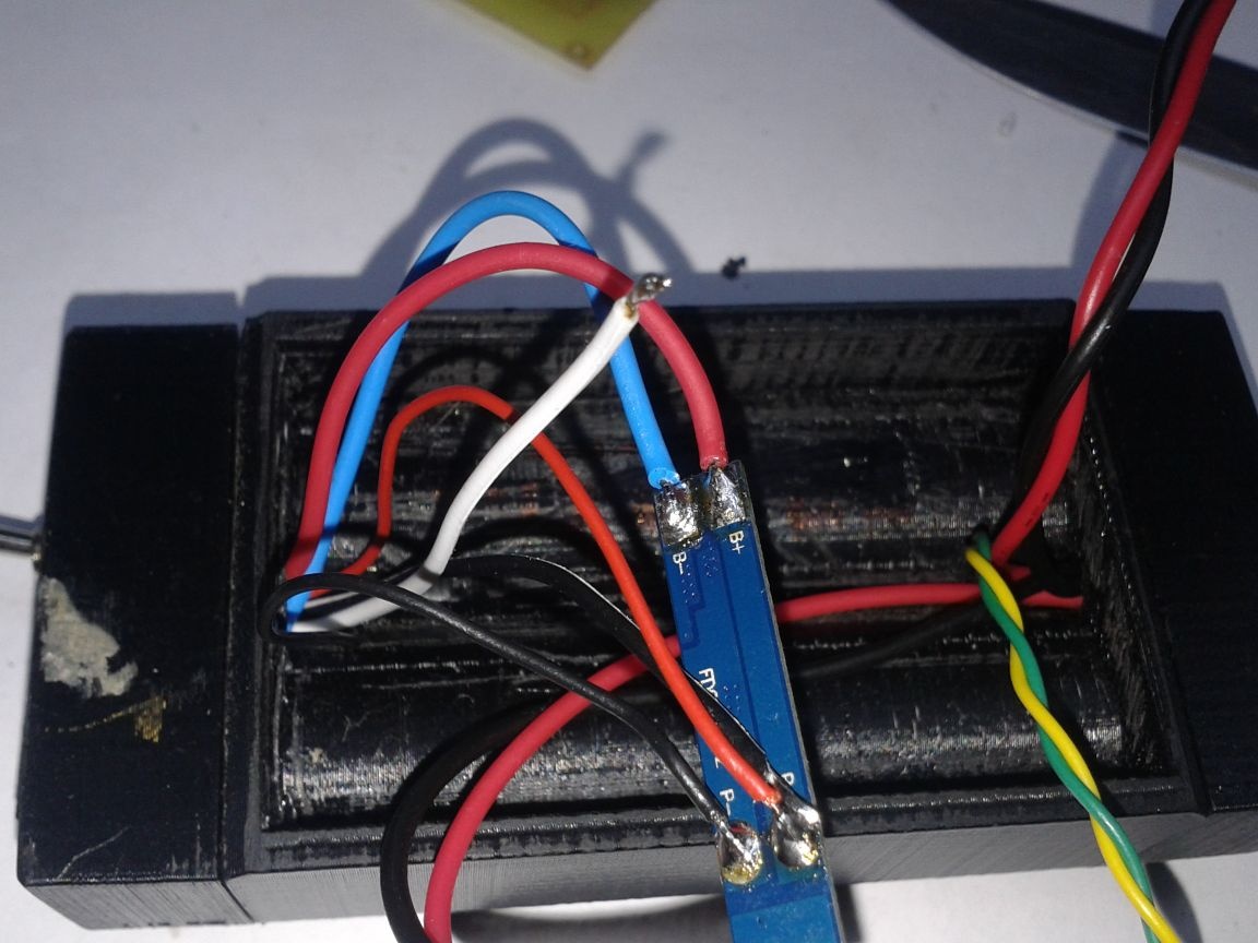
It will consist of a sting (bought in China, 8 W 5 volts, 130 rubles), two 18650 batteries (I will explain. Yes, you could use 1 type 18650 battery, solder the 5 volt boost, but this is not our method, throw it up to 20 % of energy into heat, and not at the tip, but in the soldering iron case. And two li-ion will give us a voltage in the range from 5.2 volts to 8.2 volts. There are no conversion losses, we work longer without charging. I like it. Do you like it?). The sting took this
Adjustable 18650 battery soldering iron with 5v 8W tip on ATmega8. Auto power off. Backlight Charge indication

Move on. I always want to know how long I can count on working with a device on akb. Therefore, there will be a discharge indicator for each battery. For such a forgetful person, the auto-shutdown scheme will not be superfluous. Well, since you have to solder sometimes and at dusk, there will be automatic backlighting.

For such a smart soldering iron, you need an appropriate brain. The choice fell on the Atmega8 in smd performance. Not because no other would fit. Not. I just have a lot of them, they are cheap and they have a bunch of legs)), and they will need a lot: two times three legs for the LEDs of two channels of a digital voltmeter, two legs for the inputs of these voltmeters, an output for the backlight brightness sensor and a foot that controls the backlight,a PWM control leg of a powerful polevik supplying a heater for a soldering iron tip and two legs for PWM filling adjustment buttons (I want to adjust the tip temperature, right?).

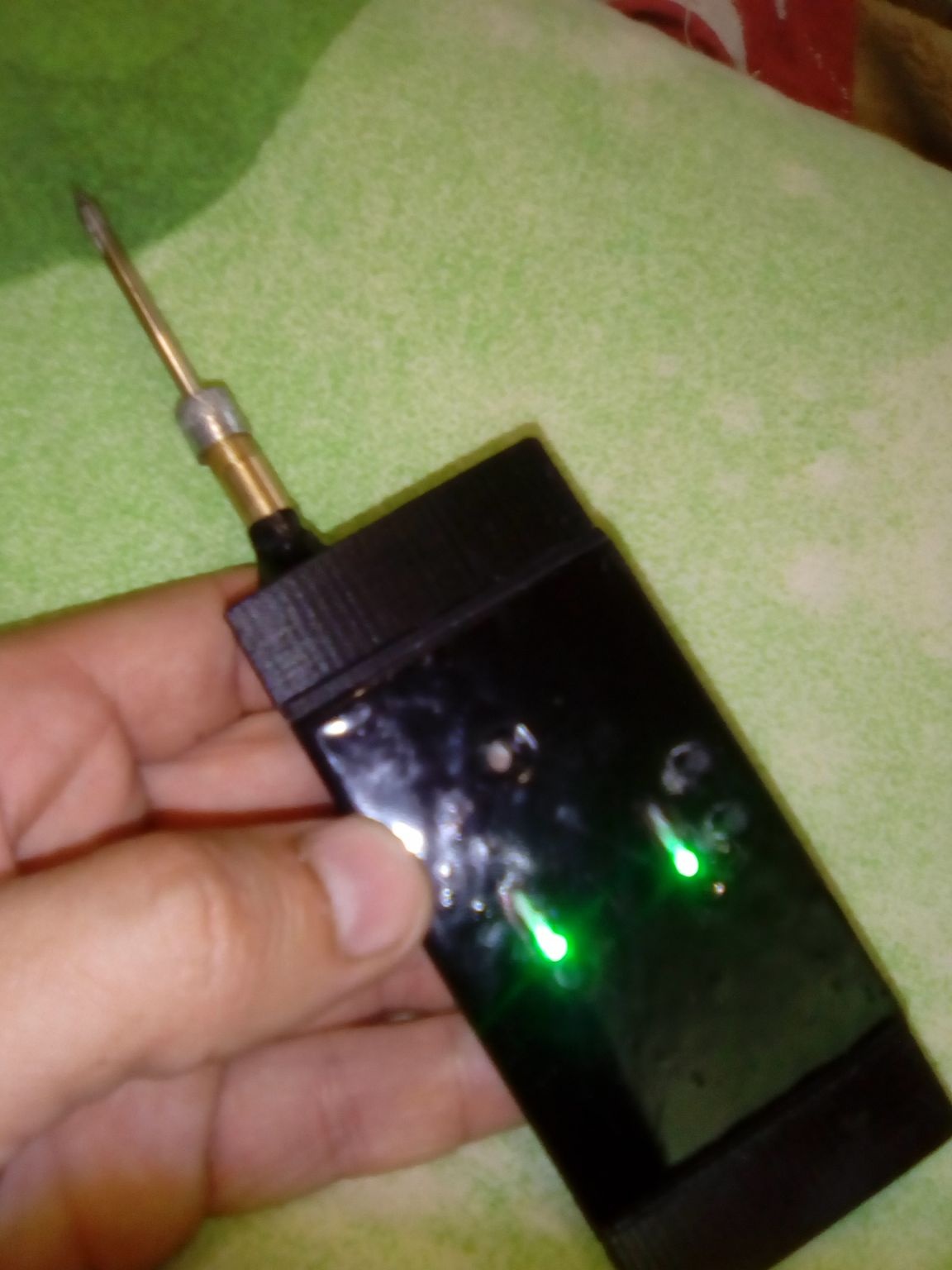
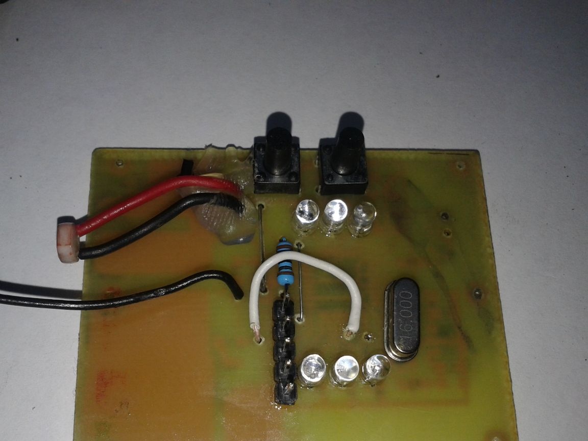
Three LEDs are used to indicate the charge of each battery. Green lights up at a voltage of 4.2-3.7 V, yellow 3.7-3.0 V, red 3.0-2.6 V. The working voltage zone is yellow and green indicator light, red is better to put on charge. With a further voltage drop, the ATmega8 will turn off the heater and backlight, which will reduce the current consumption from the battery, but it does not save you from having to turn off the toggle switch. Until the power is turned off, an alarm from the two red LEDs will blink.

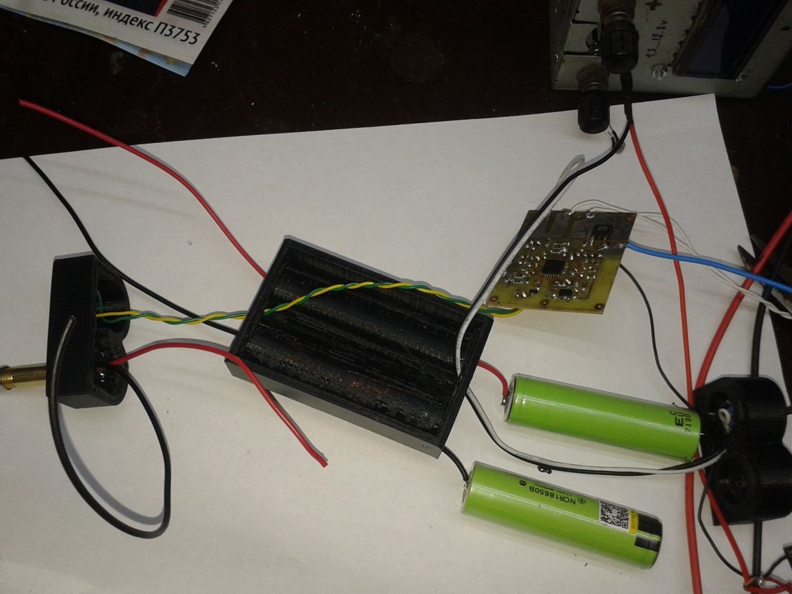
This is what happened:
cxema.pdf [189.46 Kb] (downloads: 632)
View online file:

Portable soldering iron with adjustable power output. When turned on, the power supplied to the tip is approximately equal to 100% of the rated tip power. Then, using the buttons, you can increase the power to about 150% (for faster heating, which is not useful of course) and reduce it to zero. Total adjustment steps 12. Starts when turned on with the ninth.

Automatic shutdown of the heater after 5 minutes for the forgetful with the alarming light indication (two red LEDs flashing alternately). To turn on the soldering iron again, turn off the power and turn it on again.

The backlight turns on in low light and or at that moment when the hole in front of the photoresistor is made in the lid, it will be blocked by a finger when the soldering iron is gripped. The photoresistor used in the circuit is marked GL5549, but you can use any other R6 to select the backlight.

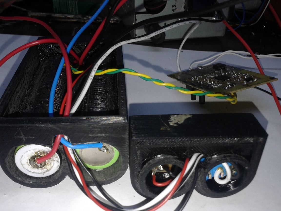
The charge indication on the three LEDs of each of the two 18650 batteries installed inside.

Firmware in HEX format
soldier2_0.zip [2.15 Kb] (downloads: 123)

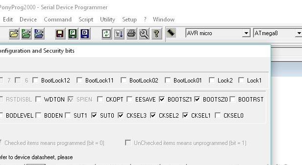
Fyuzy for poniprog such (are ticked off)

For the case, please do not scold me. Most recently, I became the proud owner of Anet A3 3D printer, and began to master modeling in the program FreeCad. Photos of my modest attempts to master a new field of activity for me, you can see below.

The case consists of 4 parts:
1. The basis.
2. The front part.
3. The back.
4.Lid.

The base was printed the longest, it took 71 grams of ABS plastic and 6.5 hours. The front is 1 hour 45 minutes and 19 grams. The back is 2 hours and 20 grams. The lid is 13 grams and an hour of work.
Total 123 grams and 11 hours of printer operation.

Printer Settings:
Layer Height - 0.2mm
Density-100%
Printing speed is 50 mm / s.
Temperature is 235.
The temperature of the table is 100.
Type of support is everywhere.
Type of sticking to the edge of the table.
The diameter of the plastic rod is 1.75 mm.
Table blowing off.
The nozzle diameter is 0.4 mm.

During assembly, be guided by your common sense. My build option is not the only one possible.
Here are some photos during assembly.

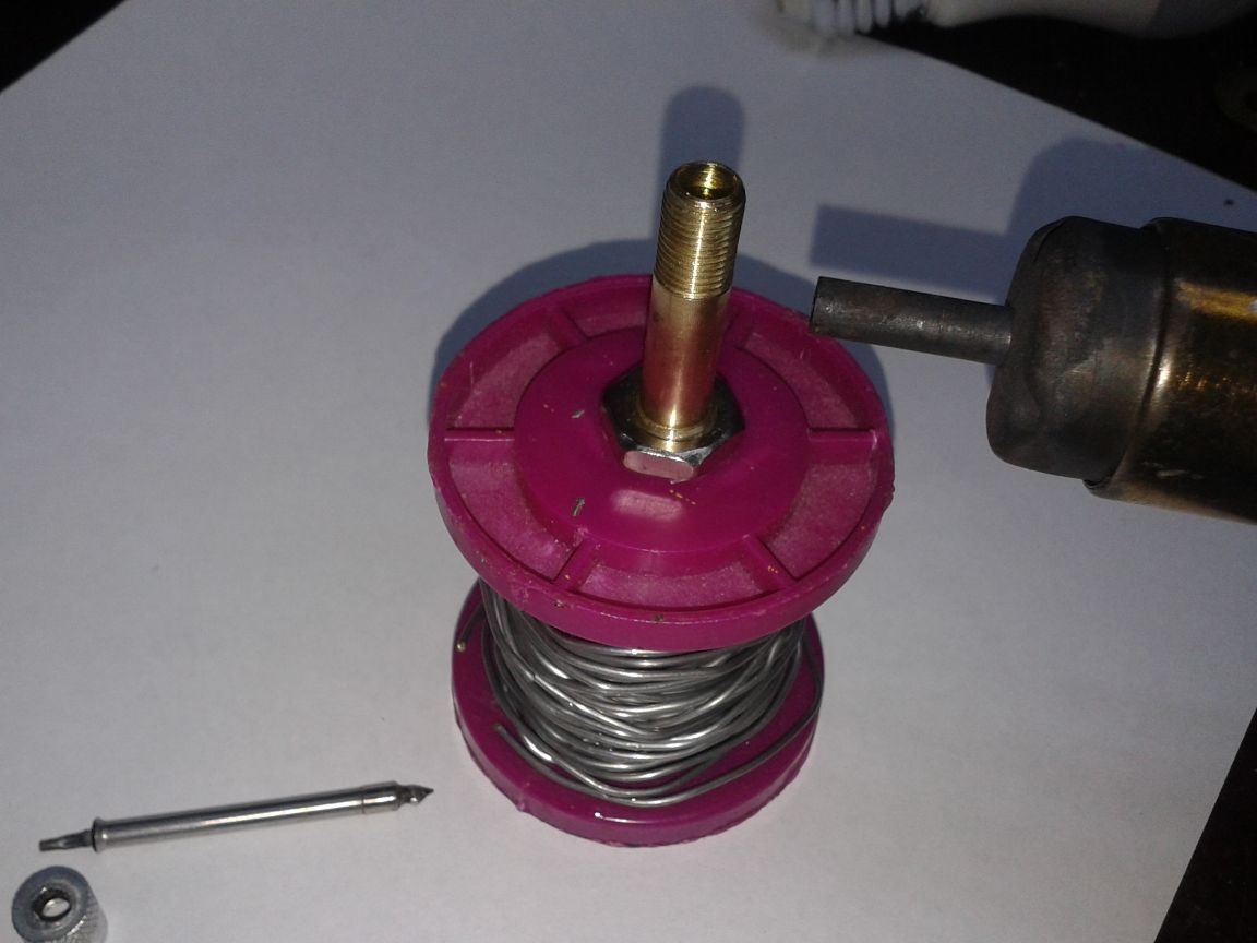
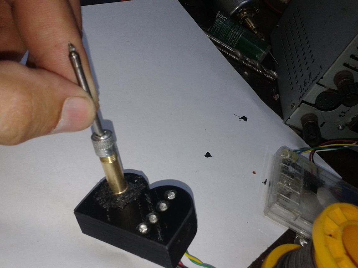
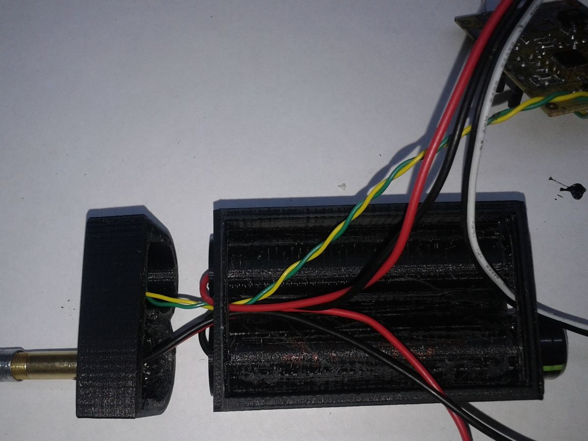
In the photo, the sting itself, a brass tube from the nipple of the car camera is 2/3 filled with plasticine and 1/3 epoxy. A soldering station dryer blows hot air at 120 degrees. The curing time was 10 minutes. The bottom left is a modified cap. The pin is bitten off and a 3.5 mm hole is drilled.

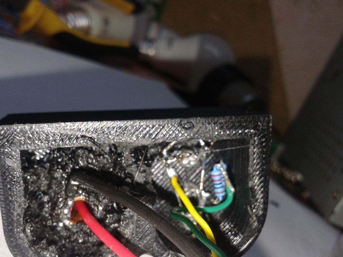
In the front of the soldering iron, drill a hole and insert a tube there. We fix the glue made of acetone plastic dissolved with acetone. Dries fast. Insert the wire into the central contact of the sting and crimp it. In a cork made of epoxy resin, we drill a through hole 2.5mm in diameter, thread a wire there and fasten it as in the photo. Solder the second posting to the tube. In the same part of the housing are LEDs with a resistor.

Front end assembly.

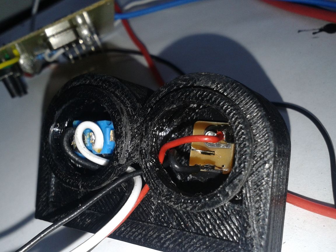
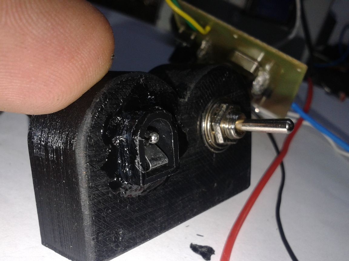
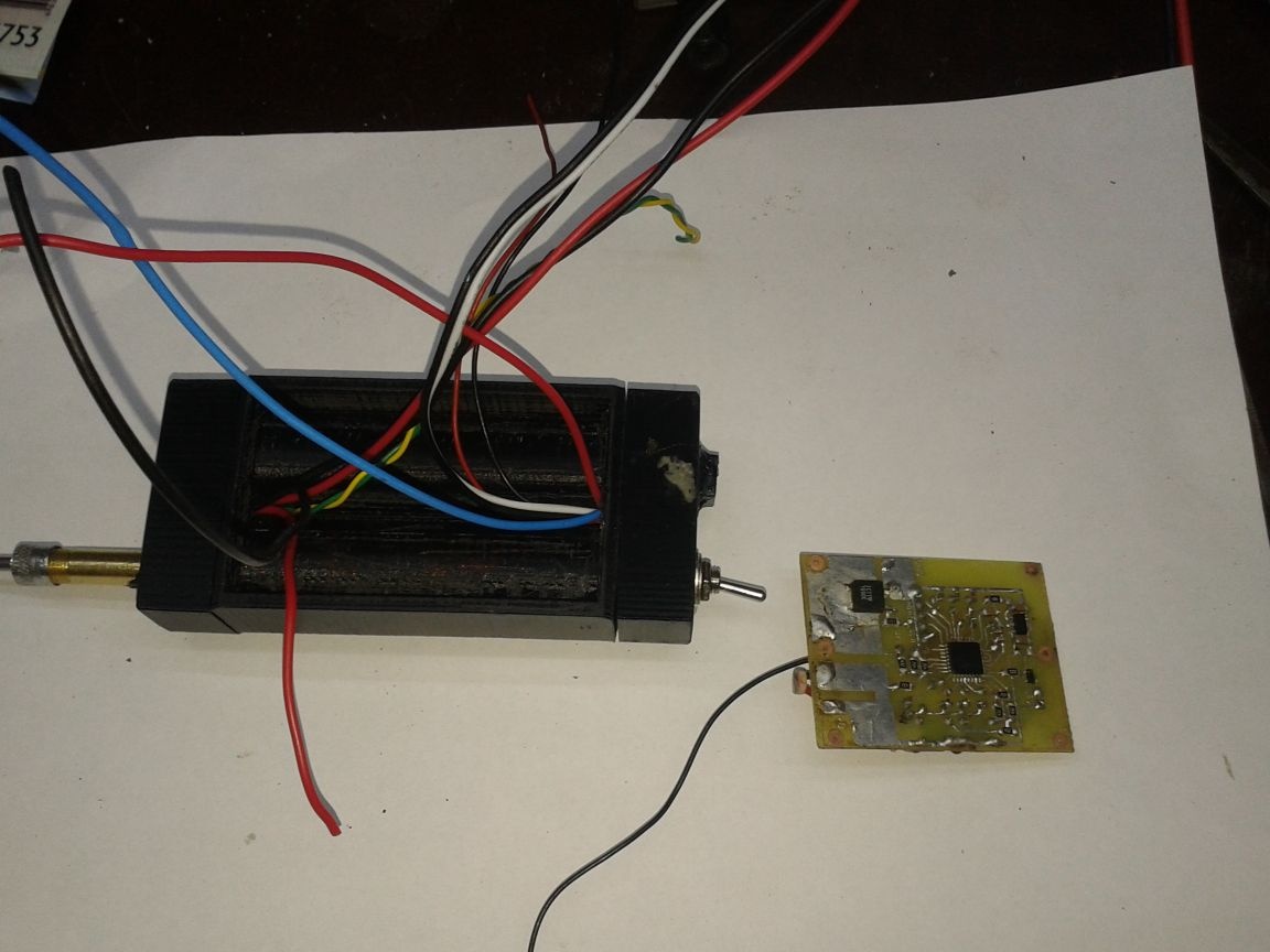
The back is complete. A switch and a connector for the charger are installed.


Files with the circuit, printed circuit board and files for printing the case in the archive.
usb-pajalnik.rar [1.5 Mb] (downloads: 169)

After printing, I had to work an hour with sandpaper and a nail file, removing some irregularities and removing layers of support. I had to drill holes for wires and modify the case with more rude means. Yes, in my imagination the case looked more hmm .. beautiful, or something. But that is, that is. I need a workhorse.I will not remodel, there is a new idea.

The case was going to live, because all the details enter each other tightly. Bonding them together made a drop of acetone on the compound. It is completely reliable. The Chinese sting was fixed in the nipple of the car tire as advised on YouTube. The nipple itself is inserted into the hole in the front of the case and fixed with plastic glue dissolved in acetone. The sting itself of course is the epitome of Chinese quality, but it is quite functional. It is attached to the neck of the nipple with a drilled cap, pressing against the base on top of the nipple filled with epoxy in which the hole for the central conductor is drilled.

The diameter of the drill for the cap is 3.5 mm, the diameter of the central hole is about 2 mm.

Good luck to everyone and creative mood.
Standalone, pocket soldering iron.
Total Voters: 58
9.3
5.4
6.3

Add a comment

    • smilesmilesxaxaokdontknowyahoonea
      bossscratchfoolyesyes-yesaggressivesecret
      sorrydancedance2dance3pardonhelpdrinks
      stopfriendsgoodgoodgoodwhistleswoontongue
      smokeclappingcraydeclarederisivedon-t_mentiondownload
      heatirefullaugh1mdameetingmoskingnegative
      not_ipopcornpunishreadscarescaressearch
      tauntthank_youthisto_clueumnikacuteagree
      badbeeeblack_eyeblum3blushboastboredom
      censoredpleasantrysecret2threatenvictoryyusun_bespectacled
      shokrespektlolprevedwelcomekrutoyya_za
      ya_dobryihelperne_huliganne_othodifludbanclose
56 comments
Author
Six months have passed. I share my thoughts about using this soldering iron from the moment it was created. It is natural that I am glad that I have it. I dreamed about him for almost two years, nurtured the concept and its "physiology".
Two batteries at 2200mA / h connected in series enough for me for about 20 days. During this time they VERY help me out, this is my REALLY WORKING tool. I found a jamb in the firmware related to auto power off. Not critical. Norm Need some kind of built-in charge controller or removable battery. Convenience will grow. The stings from China are all different. One normally solders at a voltage of 4.5 to another at 5.2 volts even from one manufacturer. . The sting is very fragile, you need a cover (cap). These are all cons. The pros outweigh. If there is a desire and time I will fix the firmware. Or rather I’ll write a new one because The flash drive with my projects was covered.
I can say one thing. When in the middle of a business trip I accidentally broke a sting (stupidly broke it with the handle of my bag), hard times came. When you’re used to having a tool at hand and don’t need to pull 50 meters of cable to make it work 5-6 minutes after turning it on, and not 15 seconds later as you are used to turning it on when you take it out of your pocket, you begin to understand what comfort and convenience. Plus I really liked to answer the questions, "What is it?" "Who is the author?" and "From China? Here are the inventors!"))
In short. The tool is working. Not suitable for all professions. But if he came up, then without him then nothing. I can’t do it now without him
Guest Semyon
Can you post a sketch for arduino, please?
erases and writes without problems. fiction and more.
So it was a two-in-one appliance - a washing machine and a printer in one housing!))))
Author
It was very easy for me to use WTDON fusion. Or by accident.
I don’t know how to laugh or cry. I collected doctor avr, took mega 8 for a test, and let her lock it down as soon as possible. Well, type check your device. I set the fuses for copy protection, and I locked my resset leg. êàî izgolyalsya over it as he could. and the fun was that on purpose I couldn’t lock it up. erases and writes without problems. fiction and more.
Author
Very nice for such a review! I have collected Doctor ABP for myself a long time ago, and did not regret it. More than 10 times it was needed, and this is more than 10 microcontrollers! And he got in the same way as you did with correctly exposed fuses that did not even change for firmware.It’s just that at one “fine” moment in the process of flashing, MK issued an error and "got bricked". In short, the desired device!
Well, everything, I unlocked all mega, I asked for it, I collected it, everything works. thanks. yahoo Tomorrow I will collect doctors for unlocking. but no matter how hard you try, but anyway, no no and it’s a shame to ask a friend already. By the way, as soon as I assembled it, as soon as a friend brought a tablet to solder the charging socket. and even the tracks were torn off in the most uncomfortable place. here he helped me a lot. so I like it, thanks to the author again.
I was not happy for long. sorry I started to flash and mega either locked up in some strange way, although all the fuses were recorded unchanged, I just put the quartz on the desired fuse. or her soul went to ..........., I don’t even know where. êàî tomorrow, or rather today, I’ll understand. In the morning it is better.
thanks. I'm going to sew. dance2
Author
We have to look for workarounds. Neither file nor archive.
Author
https://spcs.me/files/view/Soldier1.0-75317603/?Li=7711785&Lii=75317603&Link_id=1715756&Lt=1&Sn=1&name=puteec_80
something is not clear where is the firmware?
Author
Really aerobatics! The hand of the master is visible.
Here I am debugging the firmware for 10 minutes without disabling the discharge. Firmware
I made several stings out of any nonsense. the easiest 1-watt resistor with a resistance of 5-10 ohms to wind a copper wire with a small tap. as if a quick solution to solder something on the go from low-voltage power. I make cases out of everything that comes to hand. This one was made from an old mobile phone and acrylic charger. By the way, acrylic and Fomax is just a godsend for building construction. I worked in advertising, and I realized that this material is just perfect for crafts.


Here is a part of my crafts from this material. still a bunch of friends left, another lying in the closets. lately I picked up gas-discharge indicators, put on hours so much that there’s nothing to do with it.
Author
And by the way, it’s not realistic to monitor the power supplied to the sting without a display when last turned on! What if this value was equal to approximately 150%? And here in the morning you turn on the solder and it burns in 6 seconds in the trash. Or vice versa, 70%? Sit and wait while it warms up, but is it something not so? You don’t remember how many clicked. AND
I would even remember, did not recognize, because there is no indication. And so you start each ration with 100%. Do you know how many clicked? Turn off the toggle switch and turn on and again 100%
Want to add! Want to reduce it! But! Always from 100%
For the sting, by the way, a separate like! Not everyone will stir up this! I would not dare. How? Of what? The theme of a separate homemade product on this channel. I would love to read. Very interesting!
Author
The buzz body! Like definitely! Of what?
Timing is the most important feature! With a battery capacity of 3200mA / h (maximum), we have a working time of 3.2 / 1.5 ~ 2 hours. If the battery is 1200mA / h ~ 45 minutes. With such a resource, 10 minutes is too much for accidental inclusion. I need about 4 minutes a day. Those. in one session in three minutes I do not have time. No problem. Turned off, on, soldered in a minute. Heated sting for 6 seconds, i.e. you don’t even have time to bring it. Also, the selected inclusion at about 5 volt power is not random. If a cold room is clicked once in a plus, if in heat, once in a minus. Or two. A similar system really pleased me in the field. In windy weather, immediately added one unit or two. Less often, three or four. Indoors, usually one click in minus.
For delays with firmware-quarrel. The laptop is under repair. Here's a shoemaker without boots. Tomorrow I will take it, fix it, recompile and lay it out. I’ll add a soldering iron with a display to YouTube. I’ll probably post a diagram here and the whole crap. Or maybe not. Here is some kind of ebony homemade appraisal system.If someone stole and laid out the idea of ​​picking your nose with a thousand photos, then you're done! Rated 10 out of 10! If the synchrophasotron itself has collected, but there are only 10 photos, then that's it! Loser! Score 2 out of 10. Moreover, the unit is yours.
I collected my soldering iron in the case, didn’t use it much and came to what I want from a mobile soldering iron. time off is not necessary. indication of sting voltage. memory for the set temperature during subsequent switching on. turning on the backlight automatically is also probably unnecessary.
Here it turned out for me. I made a sting and a hot soldering iron. made it in 15 minutes. warms not worse. and no need to wait.
On account of the shutdown, I also thought. maybe ten minutes. five is not enough
Author
Found what a jamb. It works not only at the end of the countdown of 3 minutes, but also on incorrect readings of voltmeters. Although there is a software and hardware filter. The voltage is measured 10 times and the average value is found. It is necessary to throw out the entire unit with a trip in the discharge. Focus on the red LEDs. What else is the minus - the stub is at 5v, it needs at least 6v in order to give out 5volt stably. Those. The minimum voltage on each battery is 3.0v. When lowering it to less than 3V, the ADC of the controller will start lying, which measure the voltage on the battery. As a result of leapfrog with voltmeter readings.
In the second version on atmega328, this problem was solved by the ldo stabilizer at 3.3v
In short, I throw off the discharge. How many minutes should I leave on the timer?
Yes, but the problem now is that the reaction to adjusting the voltage with a 2MHz clock is just terrible, you can forget about the dull blinking of the red diodes when disconnecting. at 16MHz everything is fine, you just need to adjust the shutdown time.
Author
That's right! You are absolutely right! Throw out quartz with strapping. Soldering works with this firmware and it is with these fuses.
I am flashing another program, but for the best statement I downloaded I understand. I thought maybe something does not converge with the fusion. there is no favor, in a pony according to your fuses there is such a fuse. RC Osc. 1 MHz Start-time 6CK + 64 ms. that is, RC already means that this is internal clocking.
Author
So. I look at the fuses I have posted. They are factory, 16 MHz external clocking. Quartz is needed. 16 MHz With these settings, atmega8 leaves the factory. Fyuzy for ponyprog. As far as I know, they are inverse to other programs. Did you take that into account? Can I put a sketch for arduino here?
Author
Quartz stood because of experiments. Now I’ll rummage among two dozen variants of firmware for atmega8. Maybe I laid out the wrong one? There were external 16.8 MHz, internal 8.4.2.1 MHz and various program variations. If I didn’t put it out, DIKO apologize!
I collected this device, and hung with the firmware. if I flash the controller on an external quartz, then it turns off after about a minute. five minutes only works with an internal generator at 2 MHZ. what is the problem ? and the point in quartz, if the controller is programmed from an internal generator?
Author
Replaced Atmega 8 with Atmega328, set the OLED display 0.91 with a resolution of 32x128 pixels. I use it so far. I can say that at + 6 ° in a strong wind of 8W the sting is not enough. Even when powered at 6 volts. Indoors, normal at 5 volts. I did not change the board. He dismantled only the LEDs, two signal contacts of the display are soldered in place of the LEDs. Perhaps here I will stop. Everything is high.
Aspirin is generally a cool flux ... In those days ...
Well, I did not carry PWM with me !!!
... Strange, of course, it sounds, not everyone will believe, but ... did not carry! ...
I don’t know why so ...))))
aspirin from the first aid kit!
I noticed a change in the attitude of colleagues from myself, I try: "What happened?" - "Well, you're hooked on the" wheels ", you melt and smell some smelly tablets with a soldering iron!" Tinned a tiny PEL on an aspirin tablet! xaxa
He laid out a small bonfire, put a screwdriver in it
Why is it weak to attach a PWM to a screwdriver? smile
He warmed the nail on the fire and - forward. )))
Once, in the 90s, I was driving home from Moscow ... And then, having driven off a hundred kilometers, a “battery” bulb suddenly lit right on the highway ... What should I do? !!!! Comes to party !!!
(I’ll explain to the current generation ... In the 90s, if you’re on a road, on a foreign car, at that time, a foreign car, and even on “alien” numbers, it’s best not to stop at all !!!! If you’re intolerable, look for a traffic police post ( then there were such) and give the cop twenty bucks so that you could be watched while you sleep)))). And to stop "in the open field" - even in the afternoon is not worth it !!!)))
The first, of course, took the “chocolate” from the generator, the benefit in “those” machines was easy access (It was “weaving”) .... So it is - brushes !!! ... And then I remembered that where the car something, already a month lie spare brushes from the big grinder, which I bought in Germany, and at customs, when they opened the box, the bag fell out.) ... I looked ... THERE !!! They are larger in size !!! Urr !!! Reached the nearest (not equipped with anything) "place to rest" ... But there were curbs! He laid out a small fire, put a screwdriver into it, and while it was warming up, he turned the brushes on the curb to the required size !!! During this time, a screwdriver heated up. I cleaned about the same border ... I have a flux with me - aspirin from the first-aid kit!))) ... The solder had to do with those that were used to solder the "factory" brushes ...
He did everything quickly - the black “beh” added enthusiasm, drove into this parking lot .... The driver drove by slowly, carefully looking at me, turned around and rushed towards Moscow ... (Obviously, as Fima used to say from “Liquidation”, Shoba to collect a couple more soloists and ensemble!)))
... I thought I’ll get there - I’ll change ... Yeah, yeah!)))). Nothing is more permanent than temporary.))) For a long time I went on those brushes.))).
P.S. And now I’ve got it all!)))). I believe Benki them in the field nnada !!!))) Shim-regular-ya yater!)))
do not overestimate the possibilities of an iron nail,

Do not underestimate my ability to joke.))
And without PWM in the proposed version - in any way, at least if done energy-efficiently.
Ivan_Pokhmelev do not overestimate the capabilities of the iron nail, the solder will not stick, the acid will have to be dragged)). Once there were copper soldering irons that heated on coals. I imagine primitively a man by the fire who heats a piece of metal to red and thinks:
- Oh, and now with this red end of the mammoth to heat.
And you can create a soldering station with an extractor fan and a tin bath from Paverbank, for real radio fans who went to nature to relax)))
Quote: puteec_80
And I chose the current to them half of the nominal
Not from the nominal, but from the maximum. ;) If you put separate resistors, you can increase the current up to 18 mA.
Author
There will be a display - I will make an alarming indication when working at high power. Flashing or the entire display or part thereof. I’m charging from the lab. power supply unit. But somewhere lies the adapter from the cordless screwdriver - should come up. Only charging will be longer.
Understood with false positives protection to reduce battery voltage. It turned out for general power walks a tip from a PWM in the amount of 50mV. 0.1 microfarads in a chain of mass dividers and voila! The work has stopped. Soldered directly over the resistances. By the way, size 1206. I also forgot to write. And according to the diodes, yes FIGs with them, the Chinese connect in clusters of 30 pieces, even without a resistor. And I chose the current to them half of the nominal, that's how I care about them). It should be raised, why the lumens in vain disappear?
I will not redo anything else. It will work until the display arrives.
Quote: New Standard
And you can’t do without a PWM controller?
Easy. )))
He warmed the nail on the fire and - forward. )))
Quote: puteec_80
Don't know how much now? Turn it off and immediately turn on - 5 volts in place.

In order not to accidentally burn the sting, you need to provide for something: either control the current through the heater, or a timer to limit the maximum operating time at high power.
And yet, what do you use as a memory?
Quote: puteec_80
HL1-HL4 should not be powered from different resistors. There's no point.
If you do it in Thai, then yes. And if it is correct, then it is impossible to parallel the LEDs.
Author
Thanks, Ivan! Your words are balm poured on my soul! You indicated the flaws very correctly. I thought about them.
According to the dividers, I can quickly solder the resistors themselves, I do not want to bother with rewriting the code later. And so he wanted, but laziness won.
Buttons are so connected due to the topology of the board. In principle, the observation is correct.
With the introduction of an indication. Can. Right now. Another LED.
But in principle, it’s superfluous, the start is from a value approximately corresponding to five volts. Don't know how much now? Turn it off and immediately turn on - 5 volts in place.
HL1-HL4 should not be powered from different resistors. There's no point. One pulls, the main thing is that they are the same.
And instead of 7805, low-drop stabilizers with a current of consumption in microamperes are coming from China to me, the third month they are going. ((
In general, I will redo this soldered. No LEDs. The fee is 3 times less. Display, atmegu 328. Such a step of the voltmeter does not suit me. I want to know the voltage on acb to hundredths. I want to regulate the power up to a percentage. Well, the little things.
The regimen of complete hebirnation. Turn on with a clock button. It will be VERY convenient.
Ivan_Pokhmelev "Powerbank, a PWM controller and a standard five-volt soldering iron - that's all!"
And you can’t do without a PWM controller?
If you forgot the power bank, make a conclusion to the 3.7-volt soldering iron spiral. And if you really need to in the field, connect the cell phones directly to the battery
Author
Thank you very much! But 2 rubles is a little expensive for me. My desice cost me 300-400 rubles. And the toad will not sign me on these, without exaggeration, beautiful banks.
HL1 ... HL4 must be powered through separate resistors.
For a slight improvement in the circuit, you can:
1. Enter an indication of excess voltage of the tip voltage of 5 V.
2. Connect R2, S2 and S3 to C1, and not to Upit.
3. Increase the values ​​of the divider R1-R3.
4. Replace 7805 with 78L05.
Quote: puteec_80
Power Bank at 1.5 ampere-throw the link and price.

Choose
My suitcase lies perfectly in the rue, I assure you!

Do not assure me, the first time I took a soldering iron in my hands in 1969, you can’t imagine how many and what went through my hands! smile
A reference to the applied BMS is possible? And what do you use as a memory?
Author
Cheap banks do not give more than 1A discharge current. I have not encountered dear ones. Maybe there are those that give 1.5 amperes. I do not argue. But dear toad will strangle to drag in the field. And let's open a bank. Oops! And inside the same 18650 acb! Only with a converter that will eat 20% efficiency. And, accordingly, 5 part of the resource of the working time of the soldering iron. No, this is not our way.
I regret only one thing. That did not collect it a couple of years ago.
And further. You will need a cover for the sting to do. It looks very flimsy.
I do not deny that you have made the product that is optimal for you. I just answered where you can get 5 V in the field.
About false power up. Just your option is more vulnerable from this point of view, and pulled out the cable from Powerbank - I received a 100% guarantee.
Author
This driver was used to charge the batteries.

But it is better to take with balancing
Author
Corrected firmware. Fixed the error of the false operation of auto power off when lowering the voltage on the battery.
My webpage
Author
Well, in the evening I’ll try to cover this issue in more detail. Although the driver I used is not the best choice, it is without a balancer, which is very bad.
There was an idea to make two connectors for each battery separately and charge from a regular micro usb charge in turn. And the scheme would be simplified. But then you need akb with protection. On Ali, such a scarf on the battery costs about 25 rubles. We have -70.
Regarding your suggestions. Power Bank at 1.5 ampere-throw the link and price.
Situation. You soldered the circuit. Someone distracted you and you left to settle some kind of problem. Or the power toggle switch has moved in the tool box at the time of carrying to the on position. How long will the included soldering iron work? My will turn off after 5 minutes. And yours with the bank? It will suck out all the energy and leave you without a soldering iron.
Yet again. Separately, a power bank, a separate cord, a separate soldering iron. And I have a brick in which everything. And this brick will also show how much more energy is left. It will highlight in poor visibility, save itself from your forgetfulness, heat the sting just as much as necessary, does not require a stand and saves a lot of time.
Plus the cost. I won’t count the case. 40 rubles - atmega8, 130 sting, parts for 100 rubles together with the board. LEDs poked around old boards. Polevik 3055 removed from the old motherboard. Buttons from the old video recorder. I removed the battery from the old laptop. In such a partially free freeware. As the ancestors said- "In the kulak economy and .ui - the rope!"

We advise you to read:

Hand it for the smartphone ...