
And today we have a small homemade product that will make any homemade machine more convenient and safe. The author of this homemade product is AlexGyver.
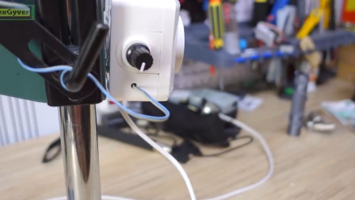
It all started with the fact that the author began to use the drill stand more often since it was not always possible to drill a hole perpendicular to the surface of the workpiece. In this rack there is a cheap drill without a built-in speed controller, and in the simplest case, to work with this thing you need to hold the trigger and put on the latch, but almost all drills already have it.


And the problem itself is that the maximum speed is too high even for drilling aluminum, not to mention stainless steel and other difficult to drill metals and alloys. As for the convenience of switching on, the drill can be left on the clamped button and turned on with a button on the outlet. Convenience is doubtful, and instantly giving maximum power is also not very cool, not for the motor, not for the drill, not for the construction of the rack. That is, there is not enough soft start. But if you take, for example, a home-made drilling machine with a powerful motor and a heavy rotor, then it needs a smooth start.
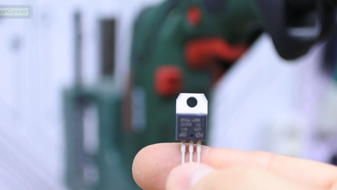
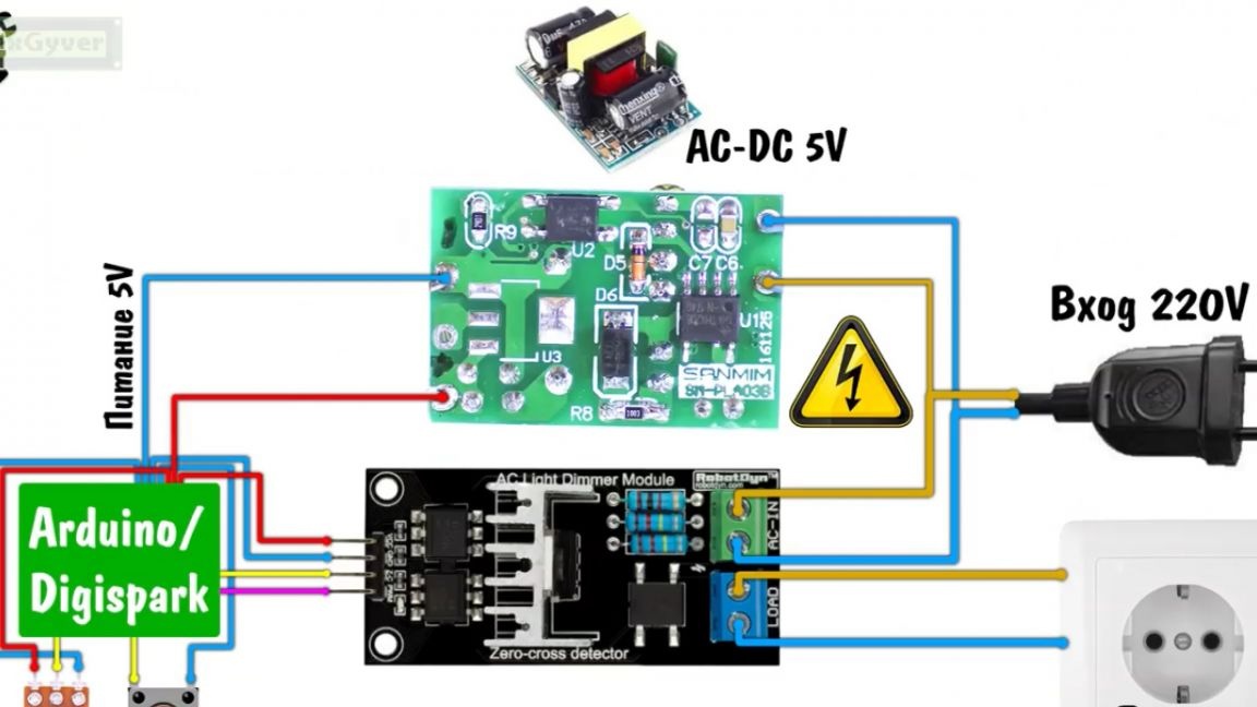
To control a non-three-phase motor, which stands here, a triac and a simple circuit will be enough.
If you, like the author, do not like to solder loose powder, then the Chinese have ready triac dimmers for 3 kW of power.
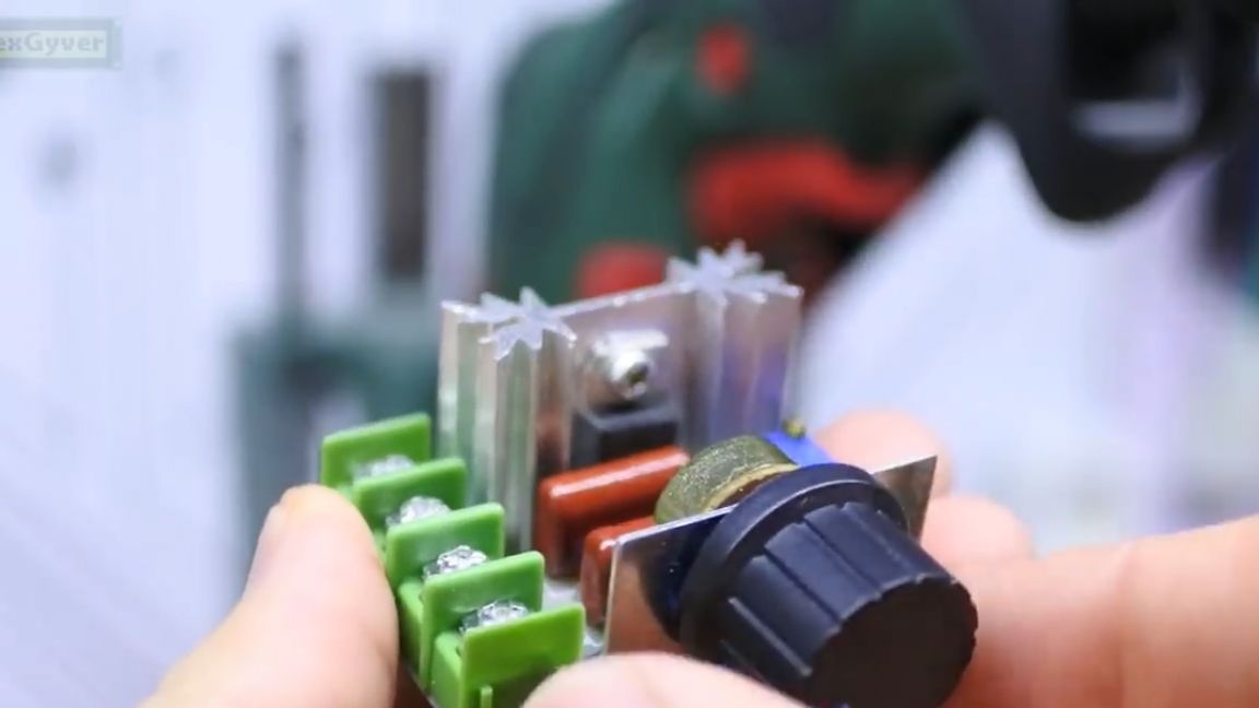
If you connect a drill through it, then we get control of the speed. The author left a link to such a dimmer in the description under the video (the SOURCE link at the end of the article). It costs generally some pennies, much cheaper than collecting it by components in our stores.
If you just want to put yourself a stand for a drill, then it's easier to immediately take a drill for it with a power regulator.
At the very beginning, the author set himself the goal of collecting a device that will perform the following functions:
1. Smooth engine start, with adjustable acceleration time;
2. Acceleration to a set value, which is limited by a potentiometer, that is, a twist;
3. The same twist during operation will allow you to change the speed;
4. The start will be from a logical button, the voltage on which is 5 V, that is, the button will be safe for wet hands, and may also be small and weak;
5. To start the machine, the button will need to be held for some time.That is, with a random click, the motor will not start.

It is possible to assemble such a machine controller on analog components, but unfortunately the author does not understand this, and offers to implement all these functions on a microcontroller. Well, by itself, the circuit will be 10 times easier this way.
As a microcontroller, we will have a platform arduino nano. It costs the Chinese 150 rubles.

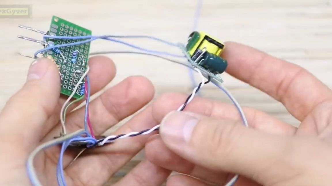
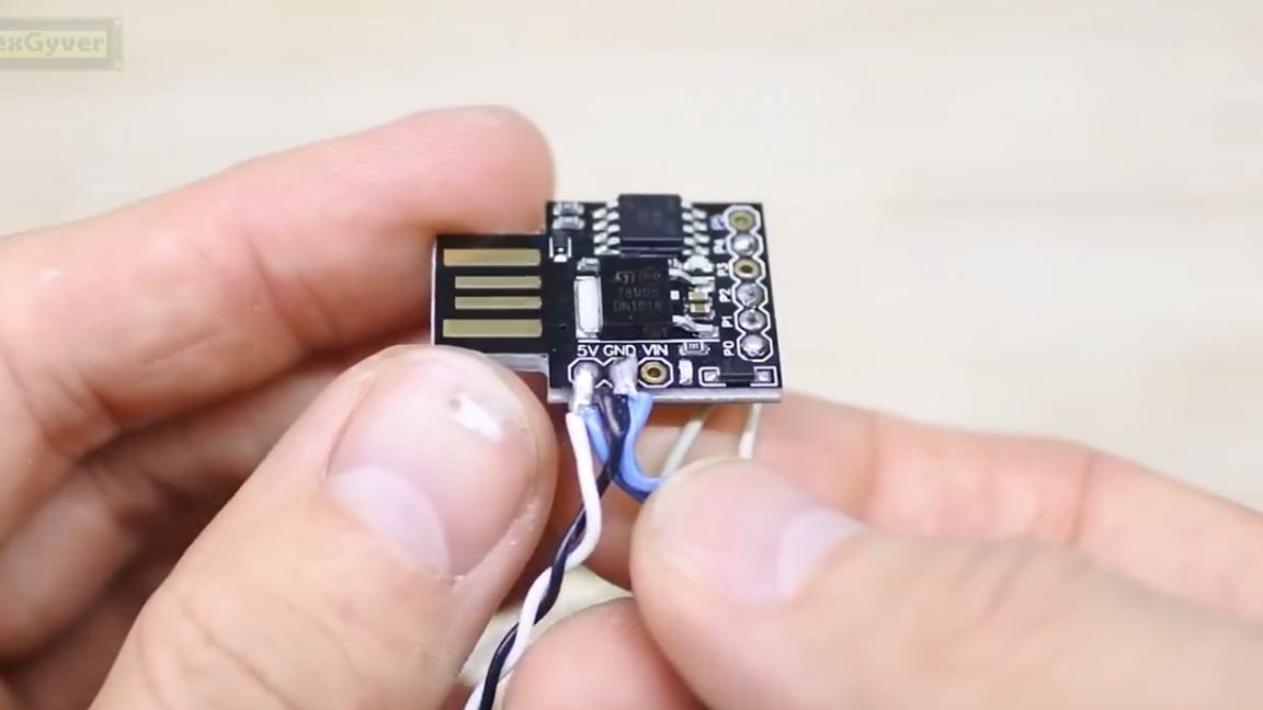
Also, this project can be run on the Digispark board, which costs a hundredth. The boards work on a 5V voltage, you can power them from a usb charger for a smartphone, but the author plans to make a compact device. Therefore, he decided to use such a mini power supply.

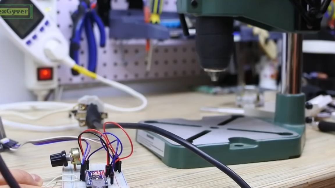
Next, we need a tuning resistor of 10 kOhm and a button. And actually we need a power unit that will supply current to the motor.
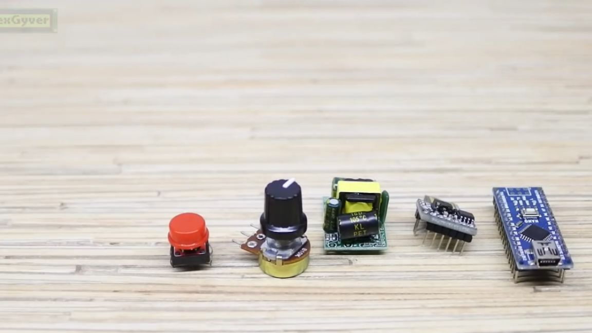
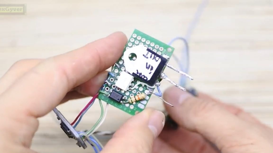
The circuit is soldered in 15 minutes on a breadboard. Also, especially for those who do not like to solder loose powder, the Chinese have a ready-made board in the same way, but unfortunately it is huge and we will not use it.
Now we need to download the firmware and download it to the board. Click on the link in the description under the author’s video to go to the project page, and download the archive.

Next, using the mega detailed instructions in the same place on the author’s website, download the firmware to one of the two boards. They work exactly the same. There is only one setting in the firmware that interests us - it is the time to reach full power (in milliseconds).
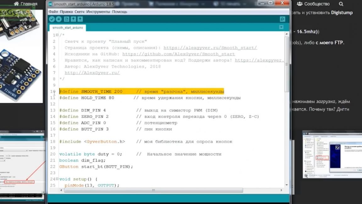
The author reminds that the firmware is loaded into the Digispark board like this: press the download button, wait for the words “connect the board” to appear, connect the board, the firmware is loaded, the board is disconnected.

Now let's put together a diagram and see how it all works. There are two schemes, of course, for different boards.
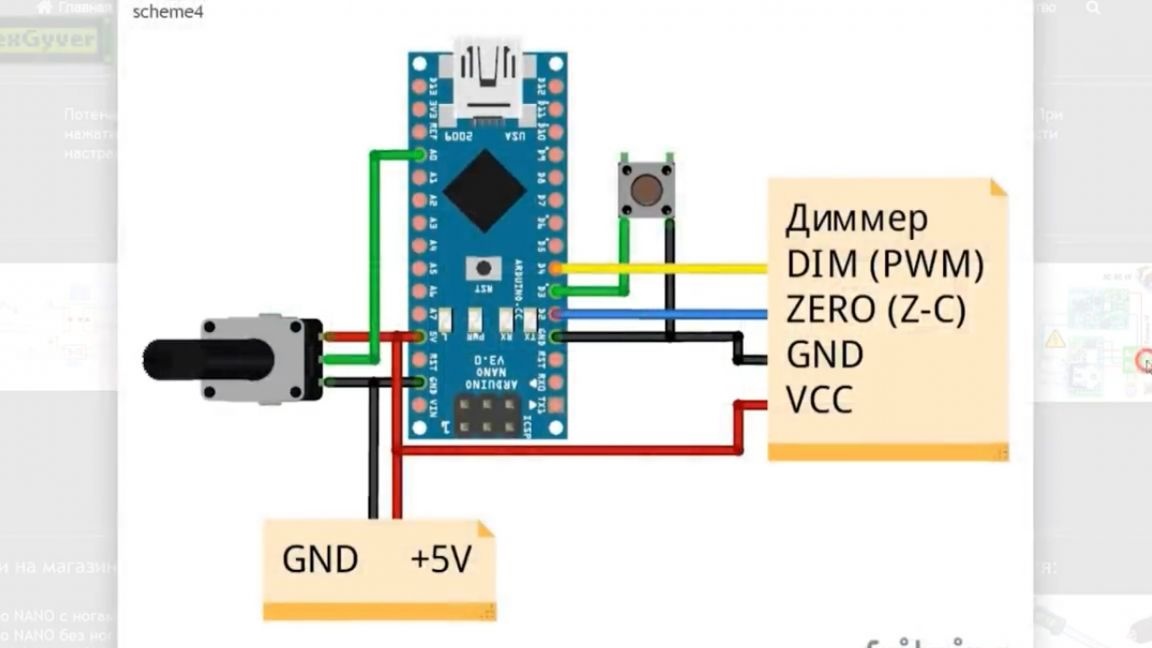
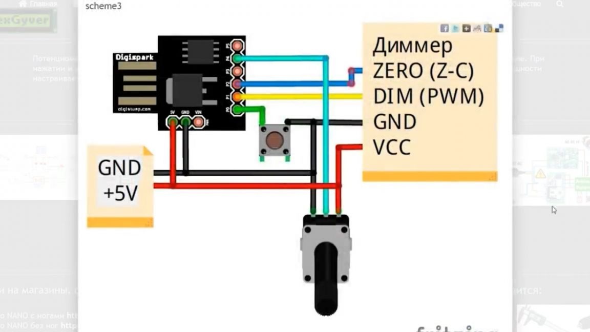
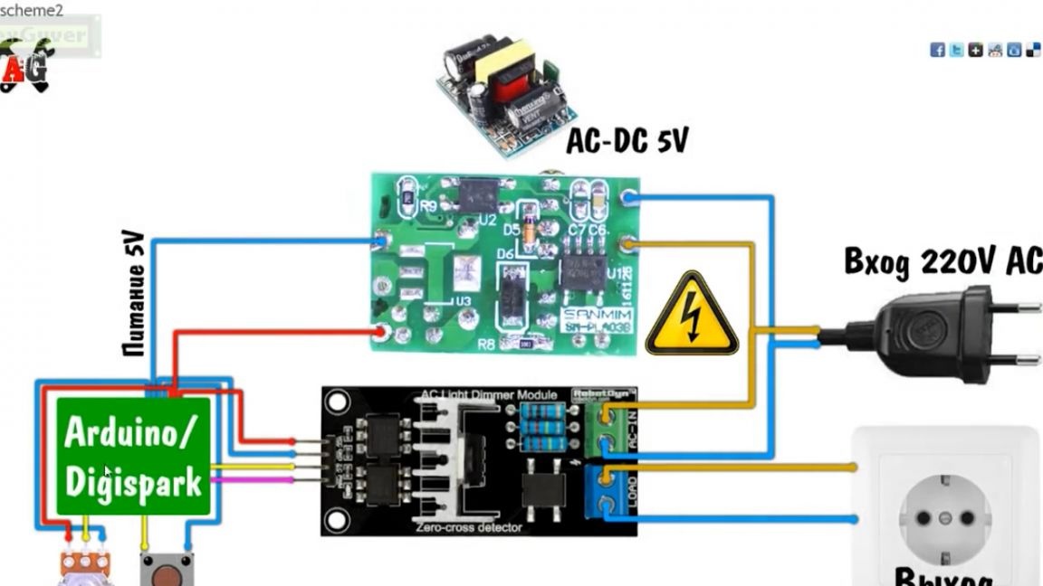
You can download them in the form of pictures on the project page (all links are in the description under the author’s original video, the SOURCE link at the end of the article).
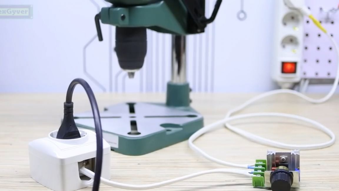
The author put together a circuit on a breadboard, and for example, connected an incandescent bulb. So watch how it works. Potentiometer sets the power from 0 to 100%. When you press and hold the button, the power rises to that set by the potentiometer in the time configured in the firmware (now it costs 1 second).
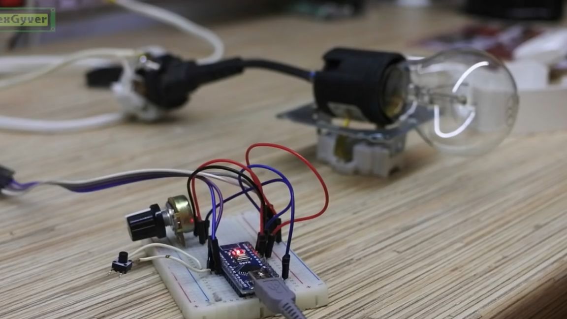
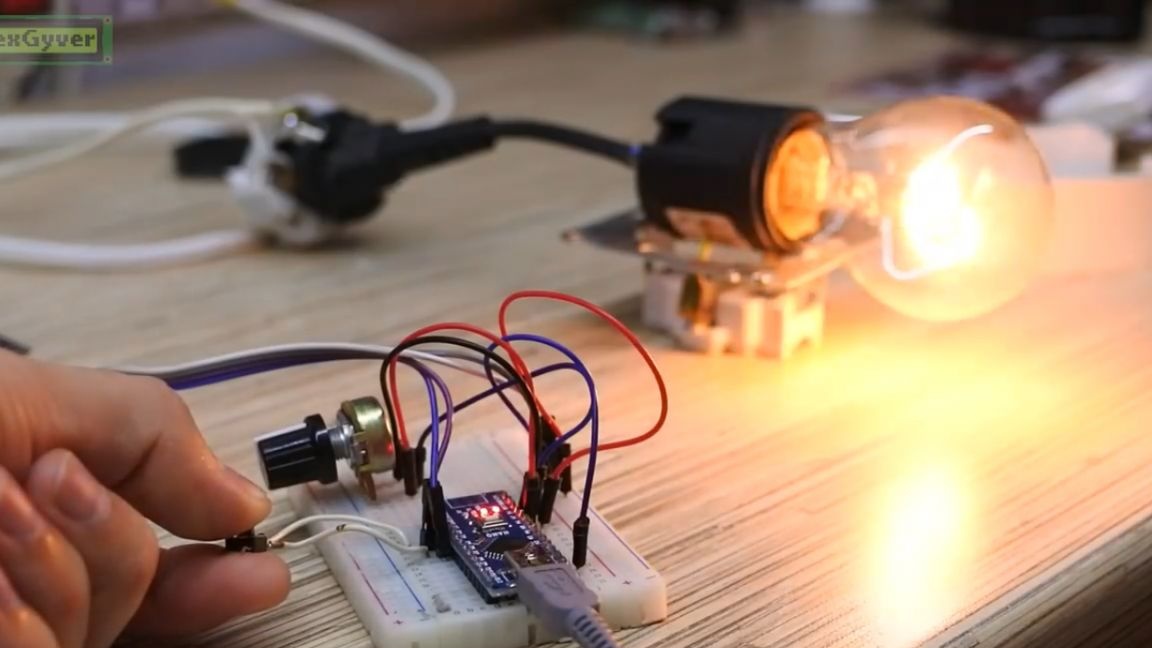
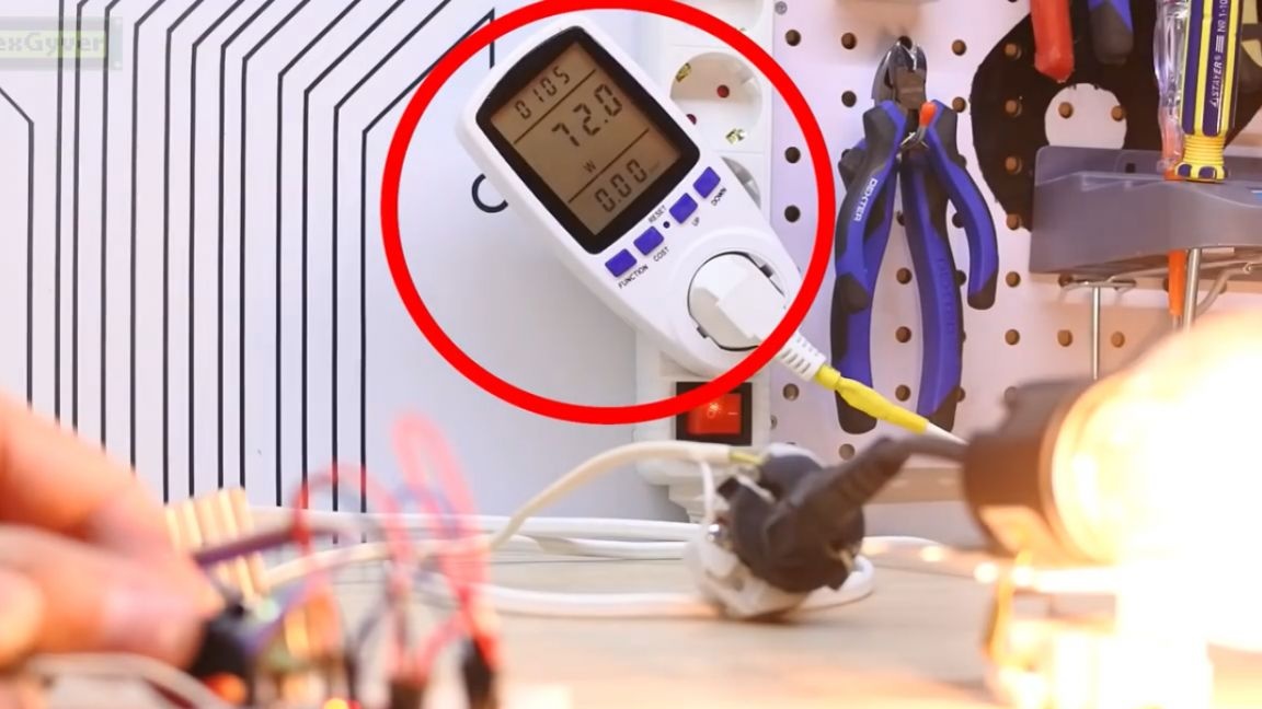
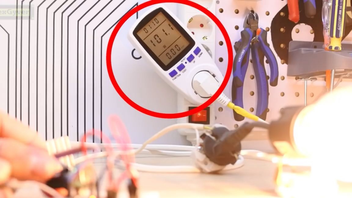
Also, during operation, you can adjust the power by rotating the handle. I think the meaning is very clear, we have a smooth start, time setting and power adjustment. And so she looks on a drill.

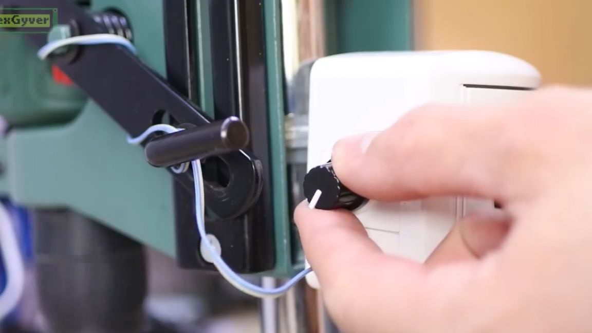
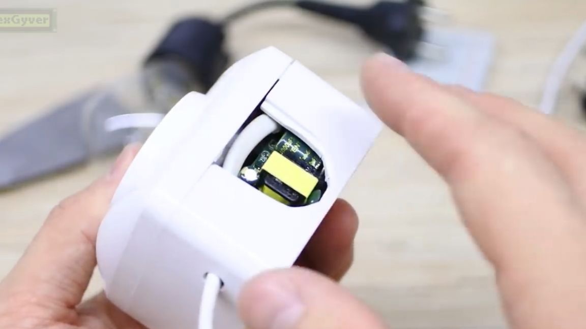
The device the author wants to assemble inside the socket for open wiring. Get a universal starting socket for any purpose. To do this, you need to buy the largest outlet you can find.
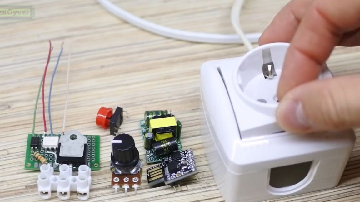
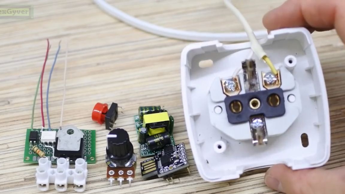
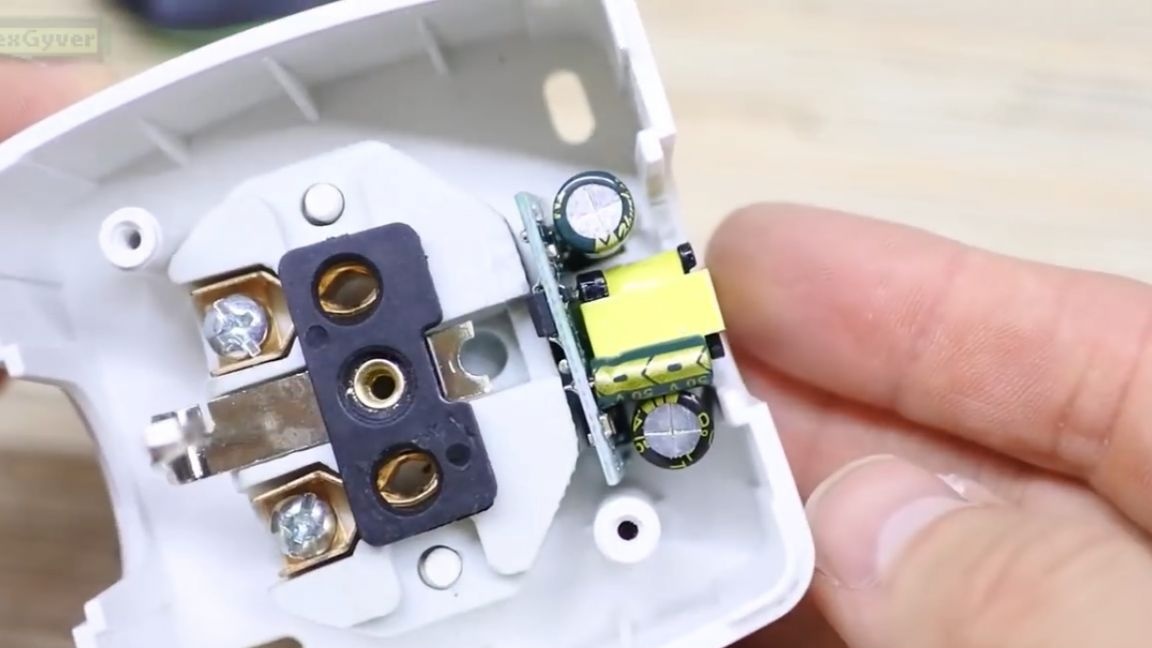
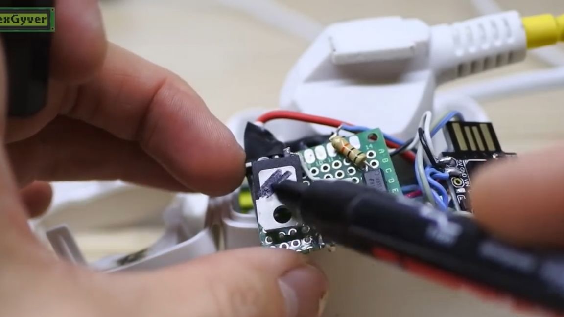
It is extremely necessary to solder the finished version of the circuit, because the jumpers do not give good contact, and the adjustment will frankly fail. Ideally, of course, you need to make a printed circuit board for such a project, but the author likes to show accessibility, who knows how - he will divorce the board itself. In order for the power supply to fit the case, I had to saw off the ground contact in the outlet. Something like this is located inside the outlet:
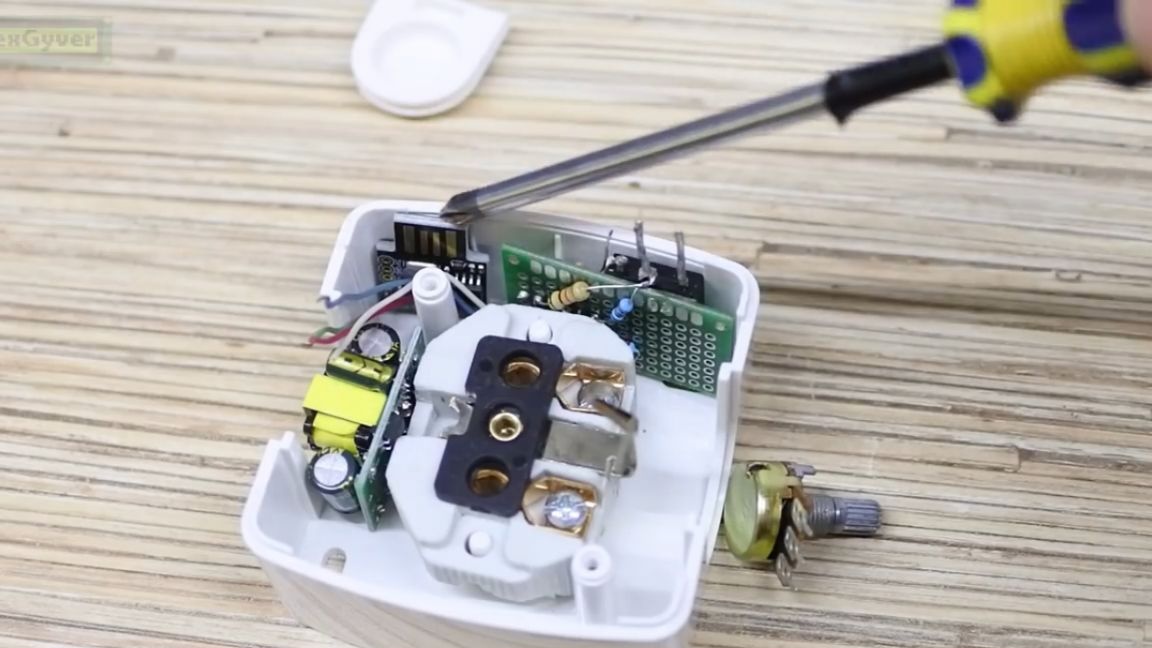
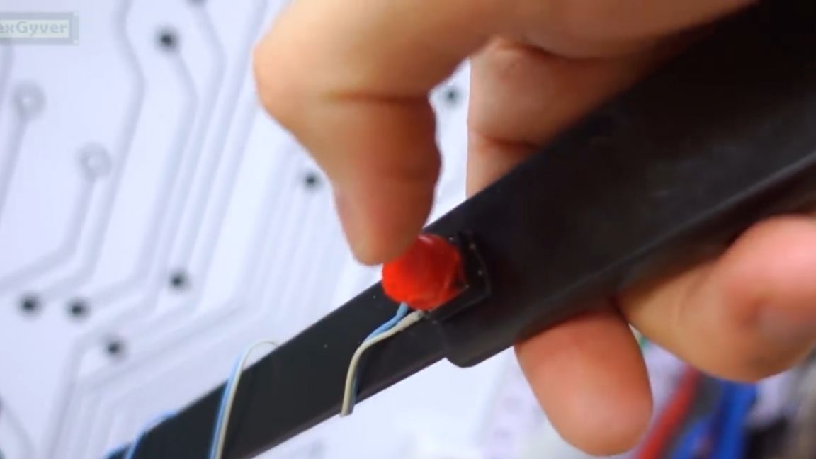
And now the circuit is assembled. Despite the number of wires, there is nothing complicated here. Just connect the 5V power where you need and the control signals. Power everything is piled up and sealed on a board. Twist hangs separately on the wires, and a long wire is provided for the buttons.
Putting it all in the case. The author was a bit confused with the connection, so his triac was dead, so I had to install a less powerful one, at the same time we will see how it will bask and whether it needs a radiator.

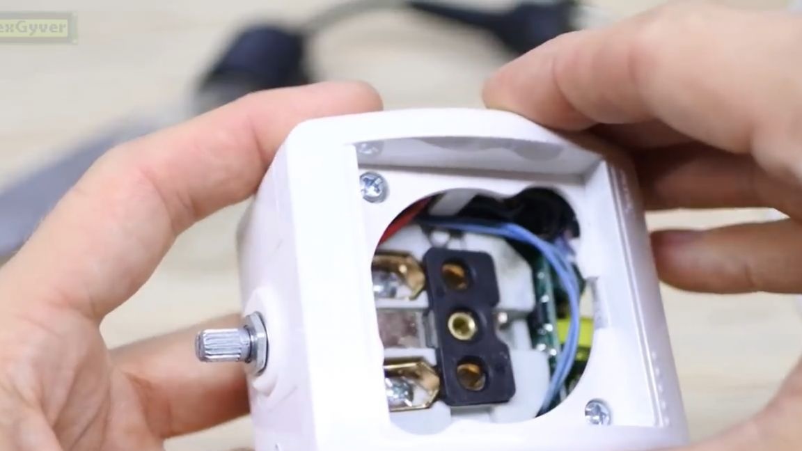
The socket closes - and that's good, but the transformer sticks out.

Well, not what - and so come down. The final touch is the button. Let's check the light bulb system.


Everything works as it should. We have a smooth set of power, with the ability to adjust it. As for heating the triac, the author did not want to make noise with a drill and collected just such a load of 500 watts.

Let's see how the triac is heated in half power mode. So that the triac radiator can be seen on the thermal imager, paint it black.
So, turn on the system and hold down the button on the board. Something starts to heat up famously - these are resistors, so you need to take them fatter, maybe even 4 watts should be put. The triac smoothly heats up and catches up with the resistor.

After a couple of minutes, the temperatures are:

The triac overtook the resistor and reached 80 degrees. In principle, according to the datasheet, you can fry it up to 125 degrees, and when working in a table drill, it clearly does not even heat up to a hundred.

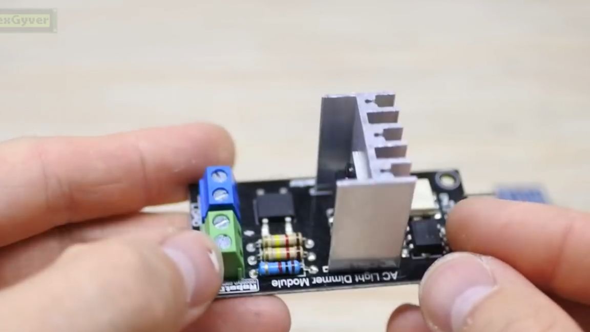
Therefore, you can not put a radiator, but if you suddenly decided to make such a system in a more powerful machine, then put a radiator, well, or just take a ready-made Chinese module and put it. It is not compact, but it certainly does not overheat. It connects in the same way, all pins are signed.
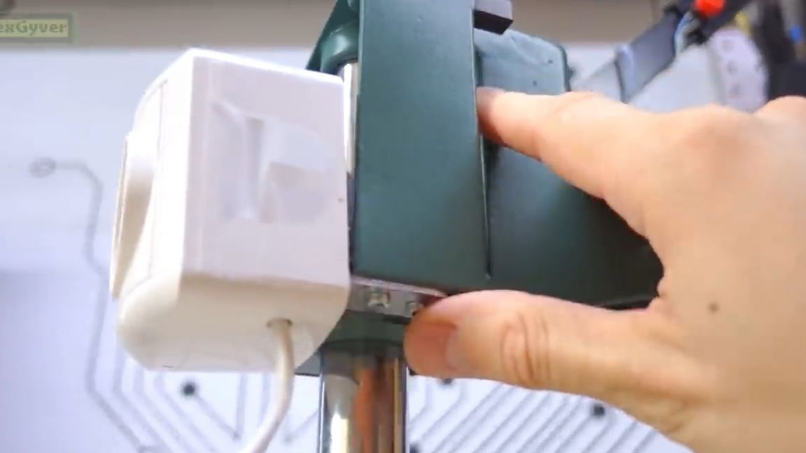
In the meantime, it remains only to fix our soft-start socket on the machine body or stand for the drill, and you can enjoy normal operation.
The only thing is that we do not have feedback on the speed, as is usually done in expensive machines. It’s actually not very difficult to add a speed sensor to this system and do everything according to its beauty, and the author will definitely deal with this issue in the near future.
Thank you for attention. See you soon!
Video: