

As Vicki tells us: “A functional generator is a voltage source that provides analog signals in sinusoidal, rectangular and triangular shapes.” Because now I'm passionate sound amplifiers, this generator came to me just in time.
I suggest you to collect this very interesting set together with me, and maybe a little more =)
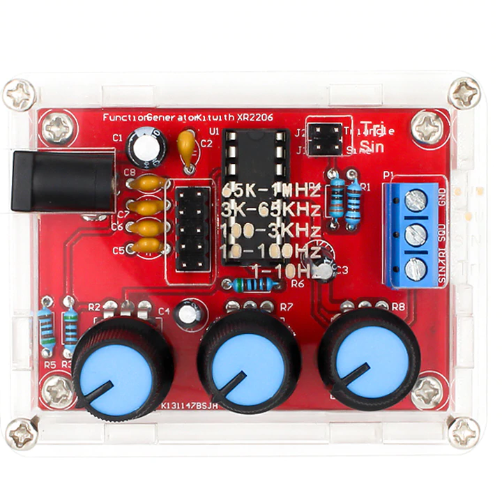
So, the manufacturer sees this constructor after assembly by us:

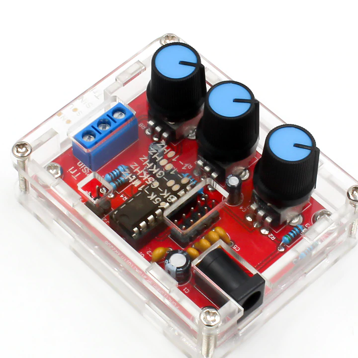
Brief technical characteristics of this constructor:
- supply voltage, from + 10V to + 16V max;
- output frequency, smooth from 1 Hz to 1 MHz
- output impedance, 600 Ohms;
- maximum amplitude of the output signal: 3.62V sine, 5.63V meander;
- current consumption, 20mA max.
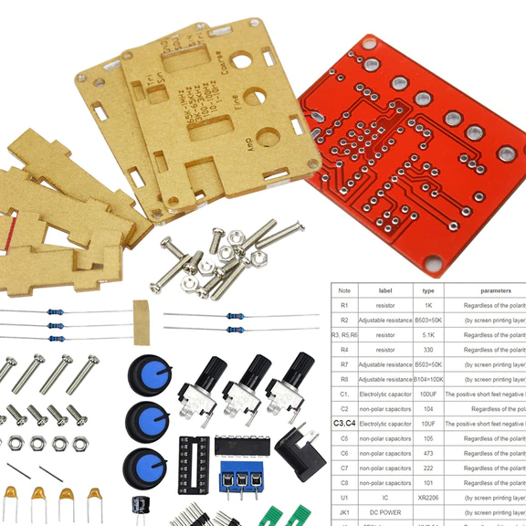
To your kit, a leaflet with a diagram and brief assembly instructions will be attached. But even if not, it does not matter, I will duplicate it here.
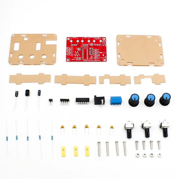
So, it turned out to decompose the contents of the mail package with me.
So, to us ...
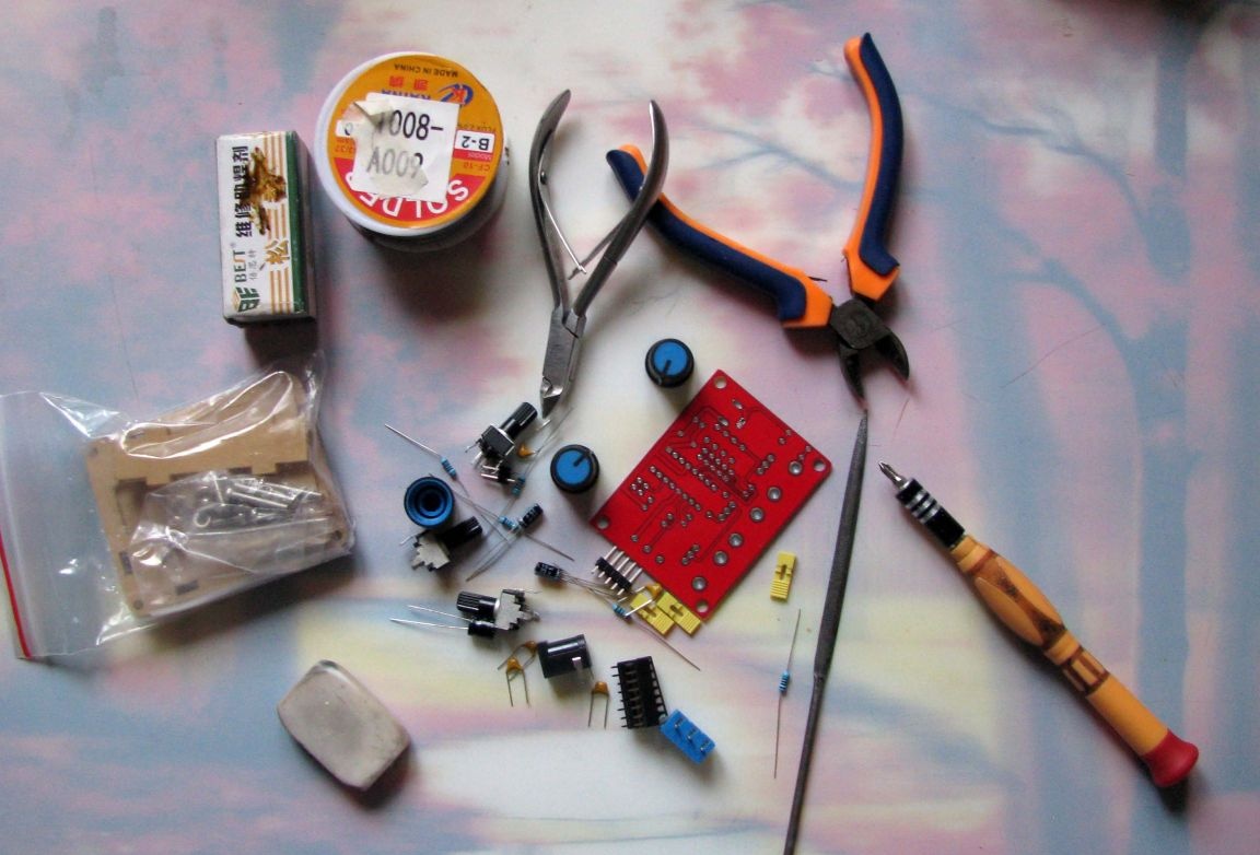
You will need:
- the contents of the set;
- soldering supplies, I have a clean rosin, solder, soldering iron;
- side cutters, if they are not there, radio amateurs fit large nail clippers for targeting actions, very convenient;
- file, they will have to strip the legs of the panels and variable resistors;
- school eraser - clean all the contacts of the circuit board before soldering to an obvious shine;
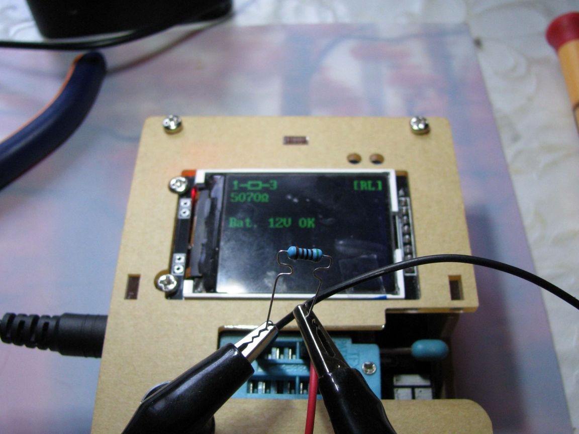
- if it is difficult for you to read the color coding on constant resistors, then you need a multimeter;
Circuit diagram very simple and intended more for reference.
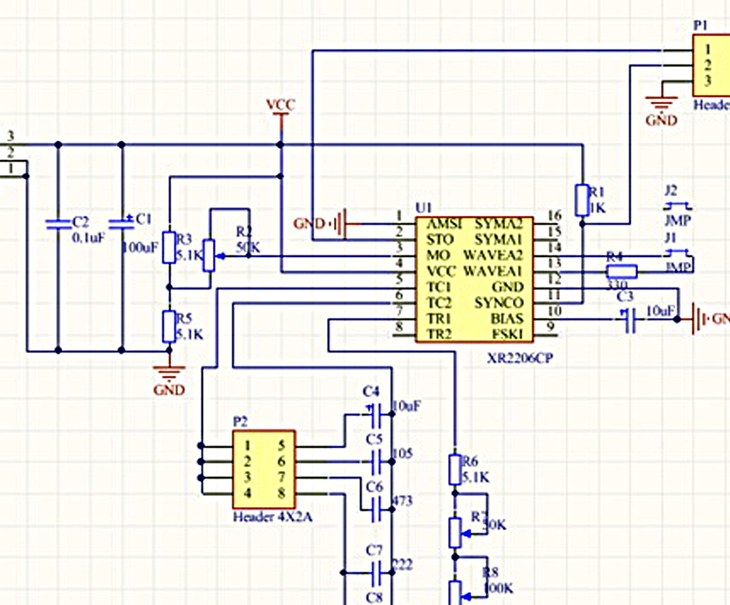
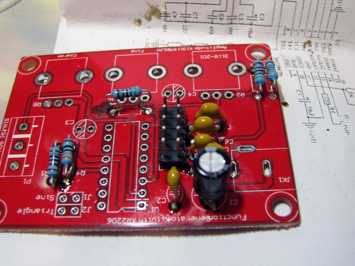
Look at the table of elements with a similar color, I highlighted the same type of elements except the integrated circuit and installation elements.
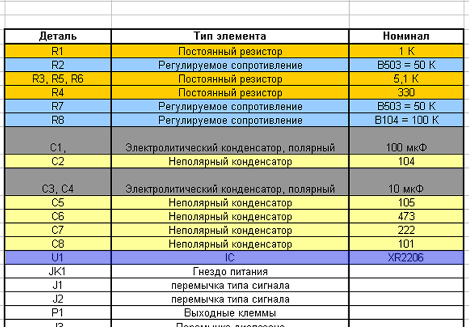
So, we start with resistors R3, R4, R5, they are of the same nominal value of 5000 ohms.
Once upon a time, the conclusions of wire elements were decided to be molded. In principle, they can be molded even now, especially if the assembly board is simple, without metallizing the holes for the components.
Then, when you click on the soldered element, it will not cause the separation of the printed track from the back of the board. In the circuit board of this generator, the holes for the wiring of the elements were made with internal metallization, therefore, it is not necessary to form conclusions, I rather did it for fun. =)
Fixed resistors.
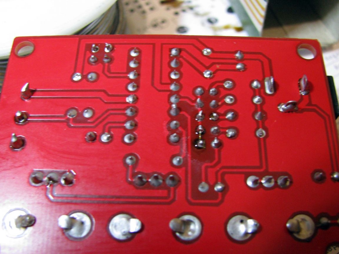
Install the resistors in their intended places, and solder them on the front side, at the same time, the solder will leak into the hole on the circuit board. After that, turn the board on the back side, bite off the extra leads, and correct the soldering, if it seemed to you that the solder is not enough.
Solder R1 and R4 in the same way.
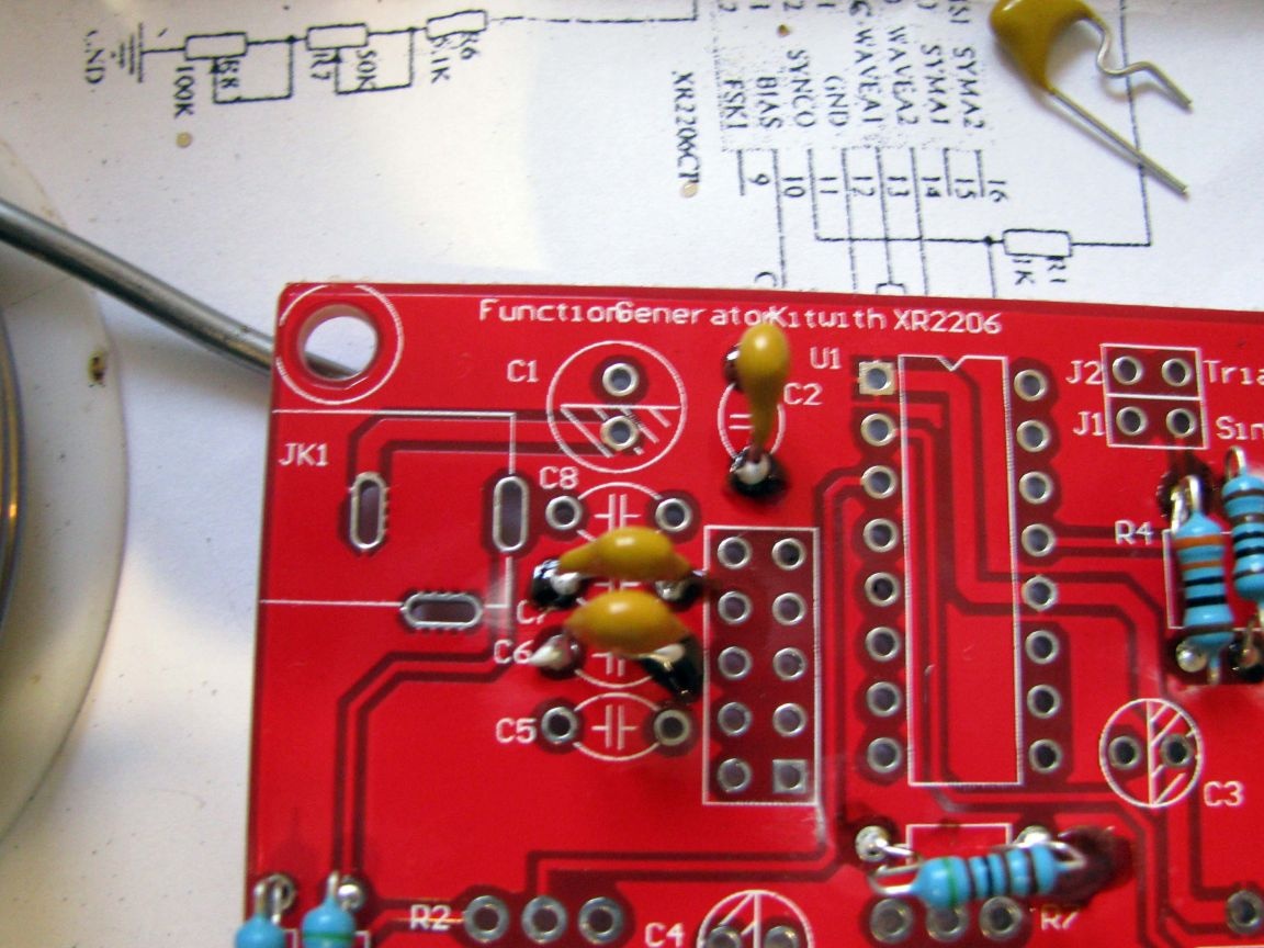
Non-polar capacitors.
Although, I have formed the conclusions, but I do not recommend this to you, in signal generators - the length of the terminals is critical.
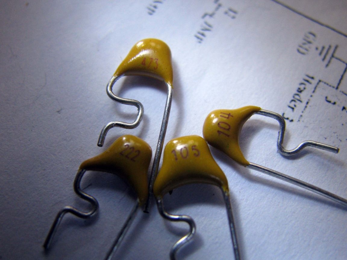
These are frequency-setting capacitors, therefore, it is better to insert them all the way and quickly solder them from the back of the circuit board, making sure that the solder penetrates the front side as well.
The capacitors themselves are marked, take a look.
First, solder C6 and C7. Then, C5 and C8 and after, and C2. That will be the most convenient way.
Comb to select the operating frequency range.
The place for it is to the right of non-polar capacitors. File the pins on the side of the comb where they are short. Do not be lazy, otherwise, soldering the comb will turn into hell.
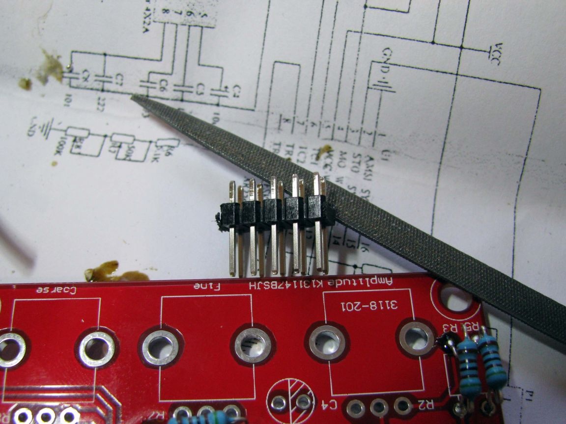
Also, go through the mounting holes with the eraser to solder the combs on the back of the circuit board.
Insert the comb as far as it will go, bite the extreme ends of the comb diagonally, check that the comb is firmly seated, and sequentially solder the contact pins.
Socket to insert a chip.
The actions are the same. On the socket itself, there is a recess on one of the ends, this is the key, orient it on the circuit board. Solder.
Electrolyticpolar capacitors.
This type of element has polarity, while the minus sign on the board is shaded, just like the minus sign on the capacitor barrel is highlighted by a strip - it will be difficult to make a mistake with this visual hint. Solder capacitor C1 - with a capacity of 100 microfarads, and then two identical C3 and C4 - this pair will be smaller.
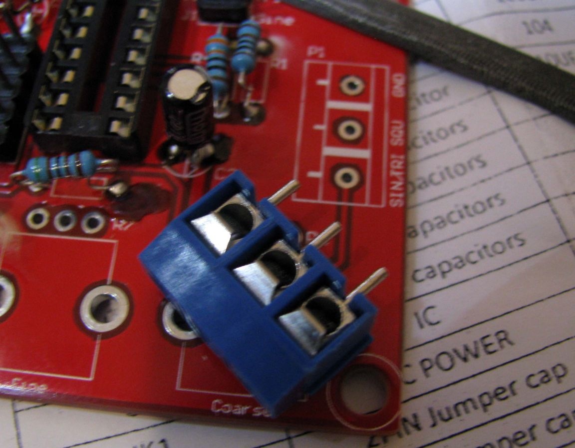
Block spring terminals.
Conductors with signals from the generator will be connected to them, therefore, orient them with the contact holes outward. Strip the contacts of the unit, insert it all the way, and solder it on the back of the circuit board.
Nest external power.
Turn the board upside down, and to the left of the C1 capacitor, in the same way, solder the socket
Variable resistors.
Find the one that is 50kOhm
Lightly strip its contacts, as well as the two housing tabs, insert it into the place indicated on the R7 board and bend the tabs towards each other, solder them first, and then the three wire leads of the variable resistor.
Find a 100kΩ variable resistor, and solder it in place of R8 in the same way.
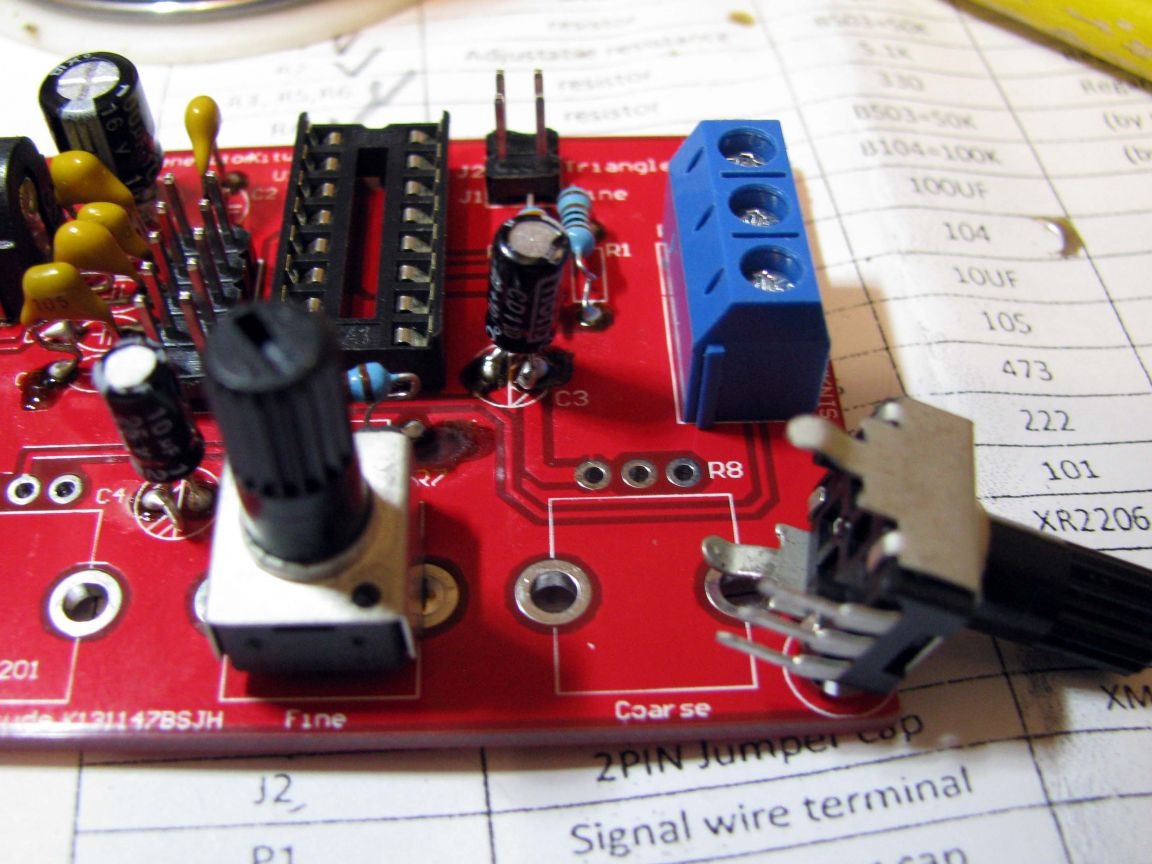
The remaining resistor is designed to fit into place R2.
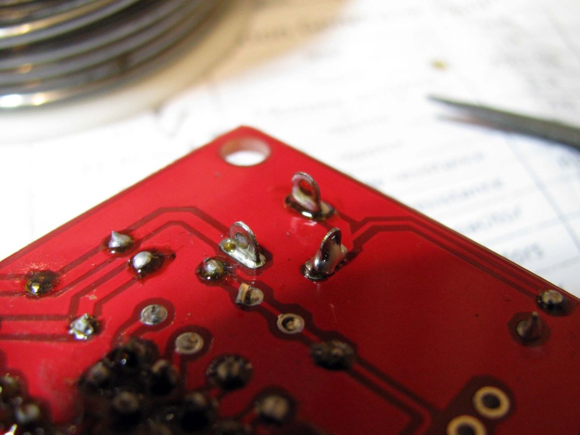
Cleaning up.
Since the circuit board turned out to be in places in the rosin, I brushed it with a brush dipped in white spirit and looked at it, “are there any unnecessary adhesions?”
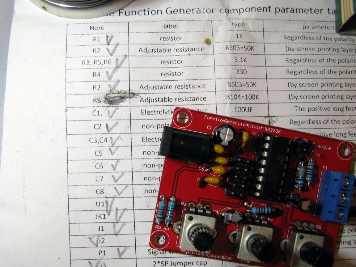
Everything, the board is ready, the chip is inserted Strictly according to the key on the socket.
On the leaflet that came with this set, I marked with a pencil those elements that consistently appeared in their places - as you can see, all positions are marked =)
Now, turn to the fact sheet this chip.
From it we see that the operating voltage of the microcircuit, attention, is from + 10V to + 26V. Sellers, all polls mention the range from + 9V to + 12V. They are mistaken, because most likely they understand only what someone else told them.
Our electrolytic capacitors have an operating voltage of + 16V, which means that we are free to use the standard + 12V to power the generator.
Other, pay attention to the picture (Figure 11) located on page 8 of the manual.
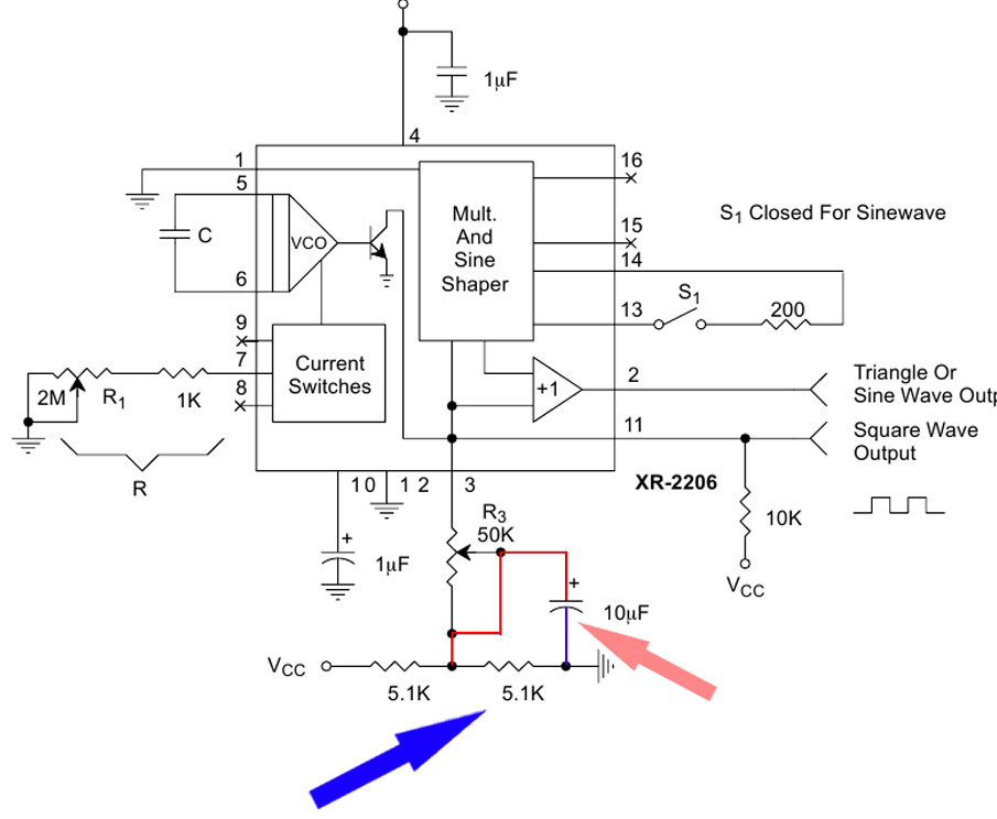
The manufacturer recommends shunting the right-side resistor of the voltage divider with an electrolytic capacitor. We do not have this. Rather, it was not.
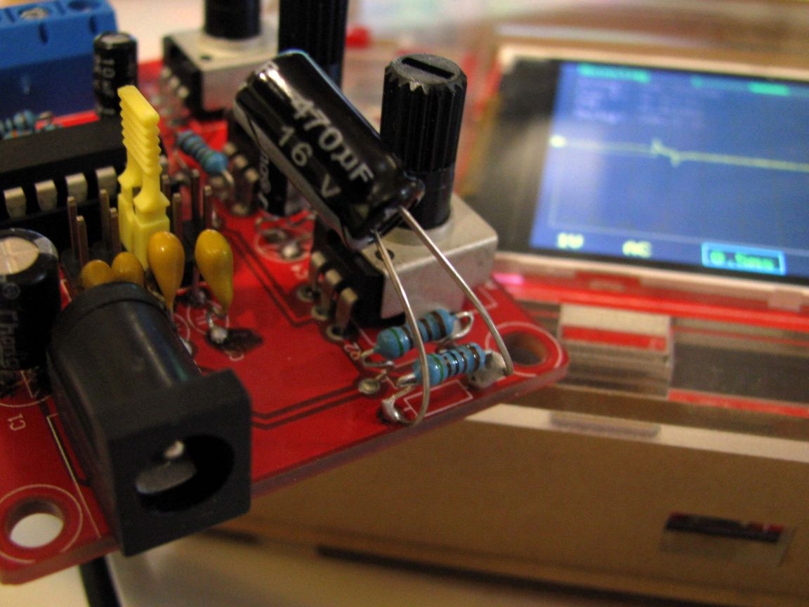
I shunted the resistor R5 with an electrolyte.
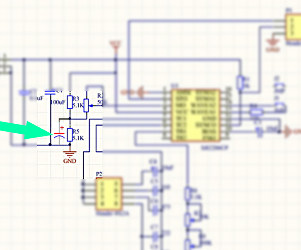
Also, in the network I found a mention that it would be better if this value is not lower than 100 microfarads and set it with a capacity of 470 microfarads. Later, on the right leg in the picture, I put on a straw.
Departed for the future.
We turn again to the reference guide. This time to the information on page 9 and the picture at the top of this page - Figure 12.This illustration shows that the microcircuit has the ability to minimize the distortion that occurs when the sine is generated.
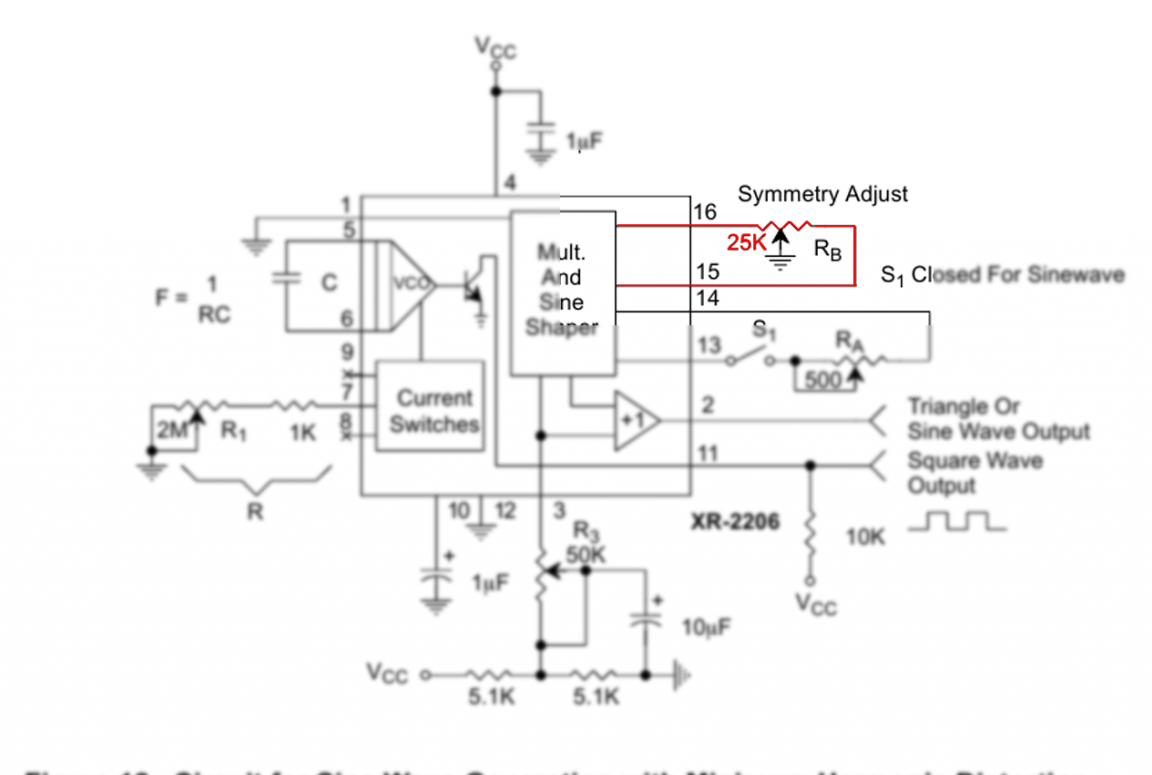
In our generator, the outputs of microcircuit 15 and 16 hang in the air, i.e. not used. By connecting a trimming resistor with a nominal value of 25 kOhm to them, and with a middle lobe to minus, we will be able to level distortions when a sinusoidal signal is generated. This, of course, makes sense, because, for me, this is primarily a generator sound.
The finished device should be placed in an acrylic case. But, there are only four nuts, although eight screws

There were no nuts for the long screws - but the problem of finding them is small - full of them. However, nothing came of it — the screws turned out to be short, and it’s good that I have a bunch of nylon screeds at hand — so I liked it too — no hysteria. =)
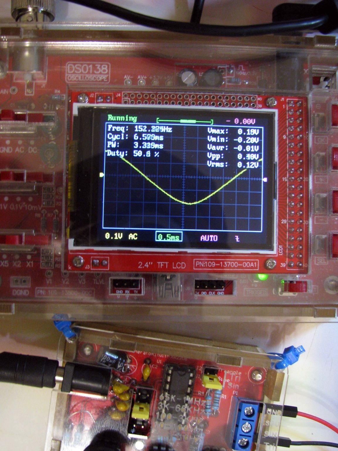
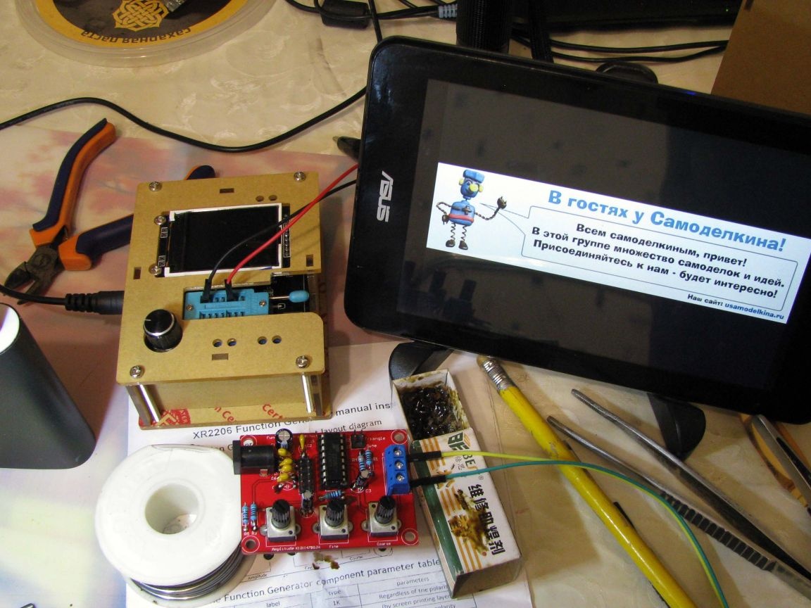
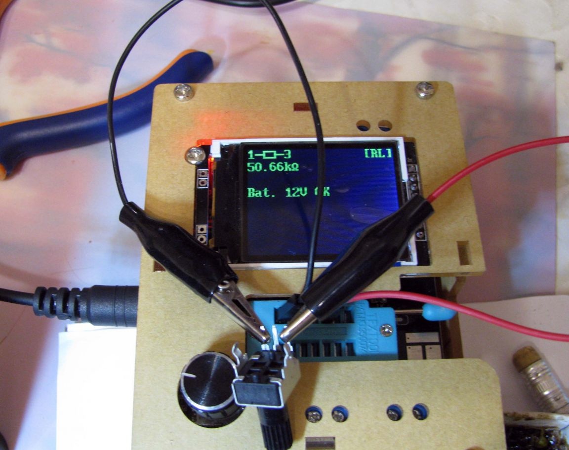
The generator is working, and maybe later, I will introduce distortion compensation by adding a tuning resistor to pins 15 and 16 of the microcircuit.
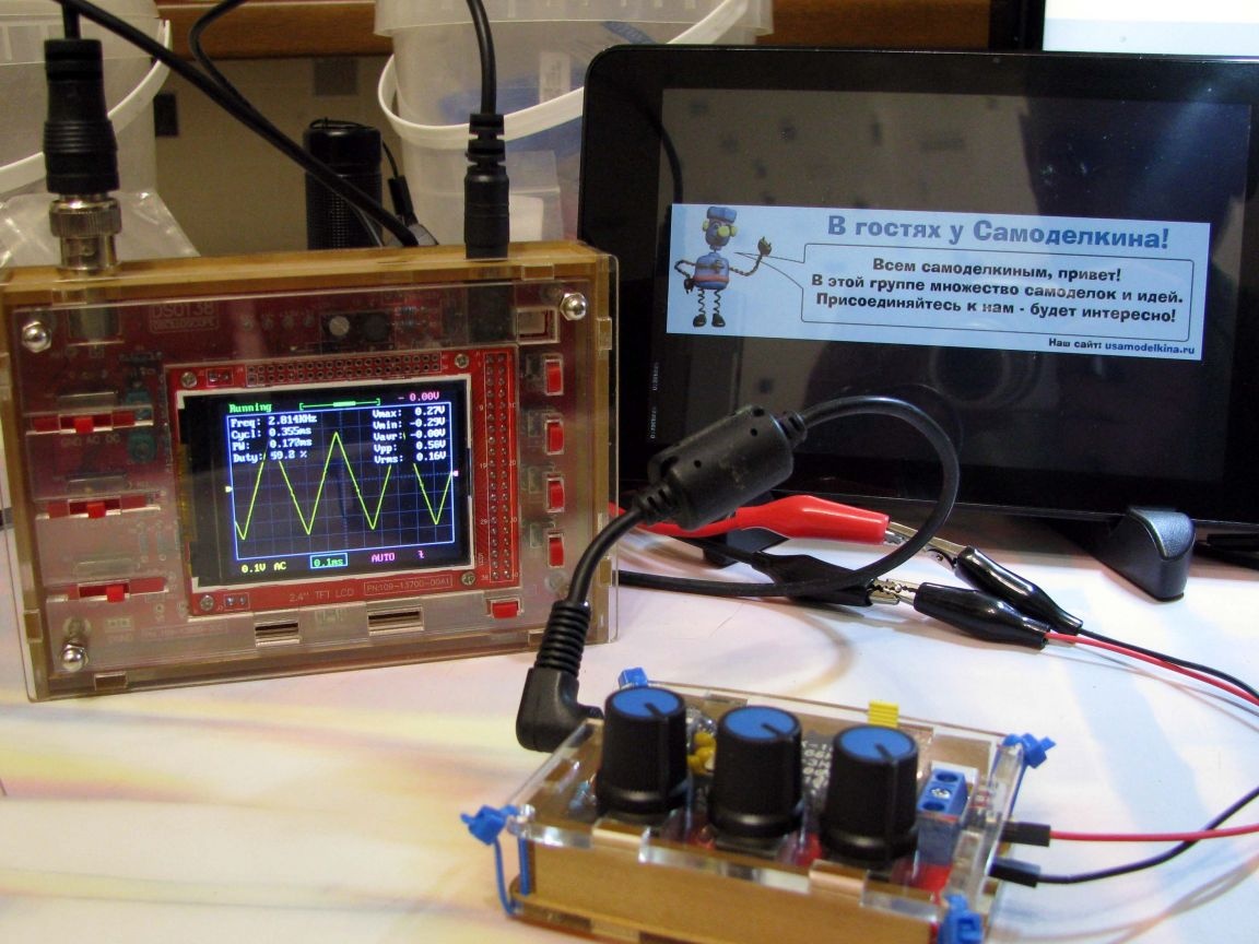
In general, I spent it not in vain, and now, instead of the software generator in the tablet, I got the opportunity to use a generally good generator made as an independent device =)
Thanks.