
Step-up voltage converters with low-voltage power supply are very often implemented in a variety of homemade products. Now the market offers us quite good ready-made solutions, but to take and use a ready-made board is somehow uninteresting. Much nicer when you do it do it yourself.
The author of this homemade product is AKA KASYAN (YouTube channel "AKA KASYAN"). The proposed converter can be involved in the construction of home-made powerbank’s, converters for a multimeter, power a line of LEDs or LED strip from a low-voltage source, and so on.
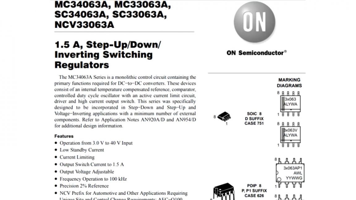
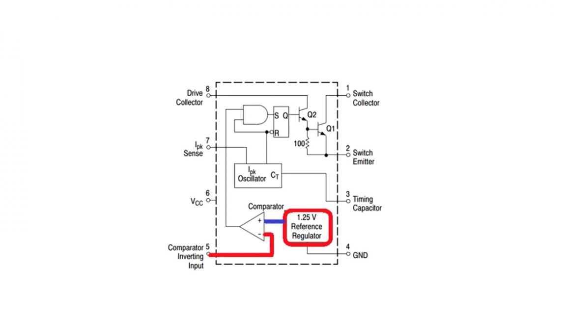
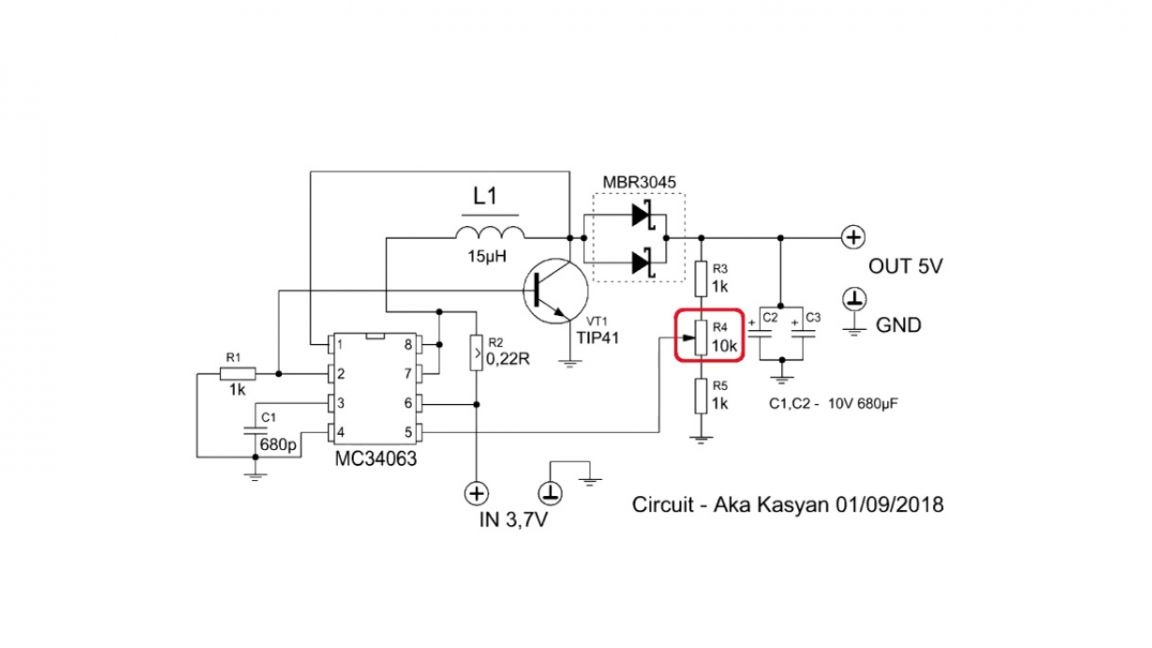
With the mc34063 chip, perhaps, every radio amateur is familiar. This is a specialized microcircuit on the basis of which you can build pretty good dc-dc voltage converters that increase, decrease or inverse.
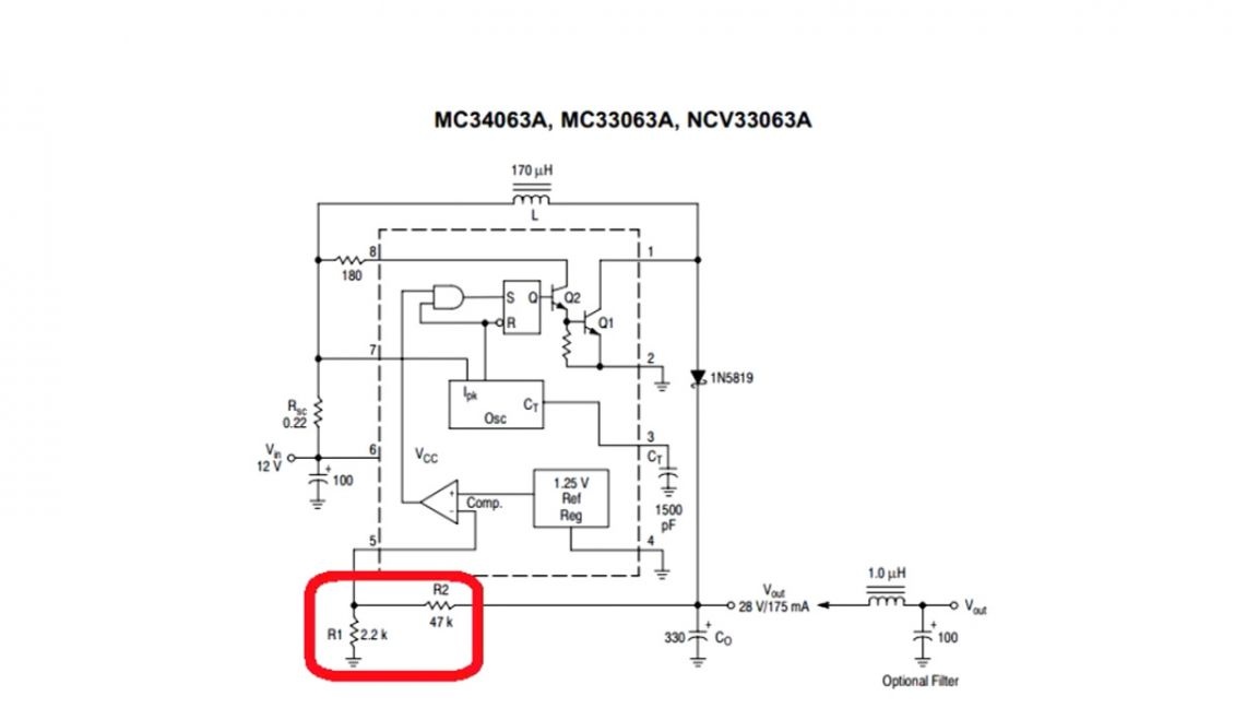
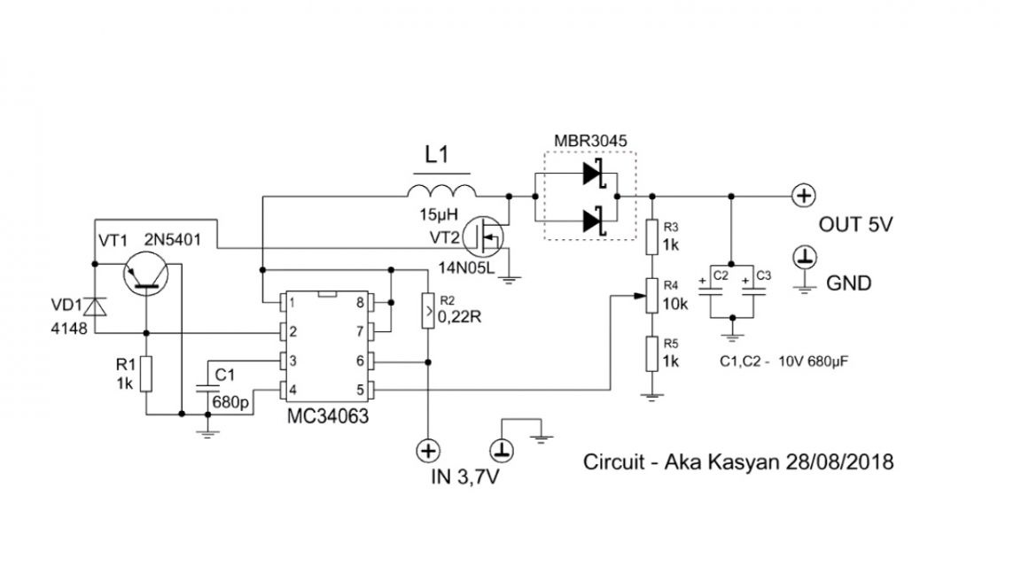
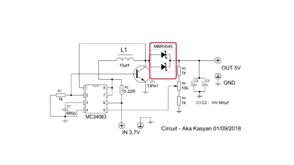
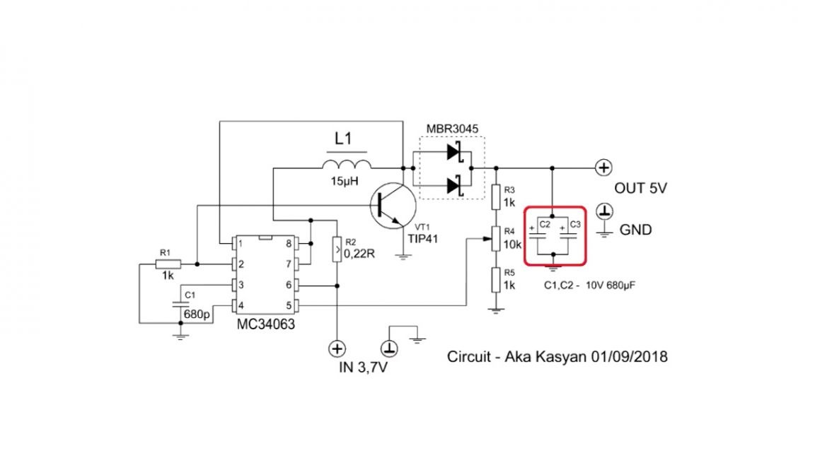
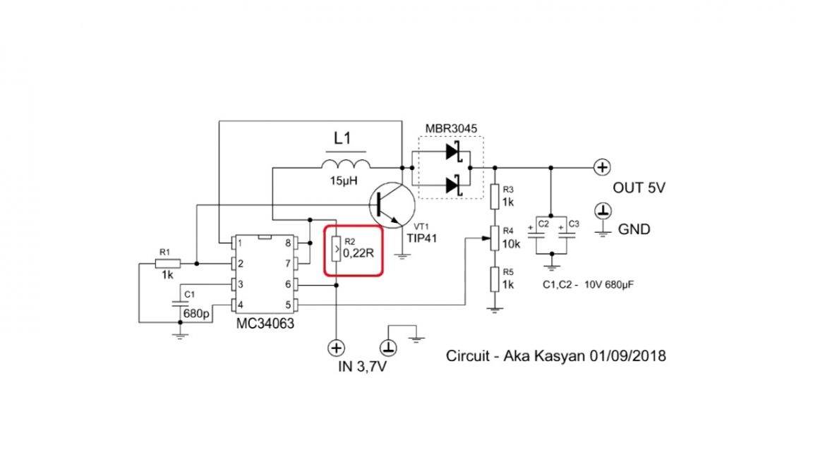
A simple boost converter circuit on this chip will look like this:
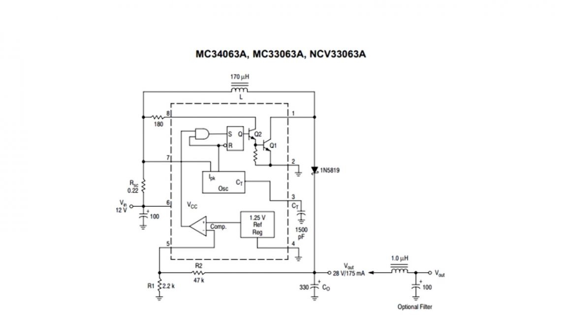
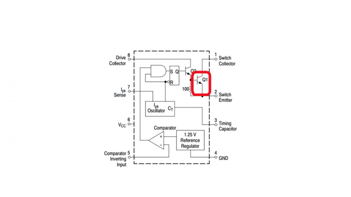
The microcircuit is good in that it already has a power transistor inside, so that the output current can go up to 1.5A.
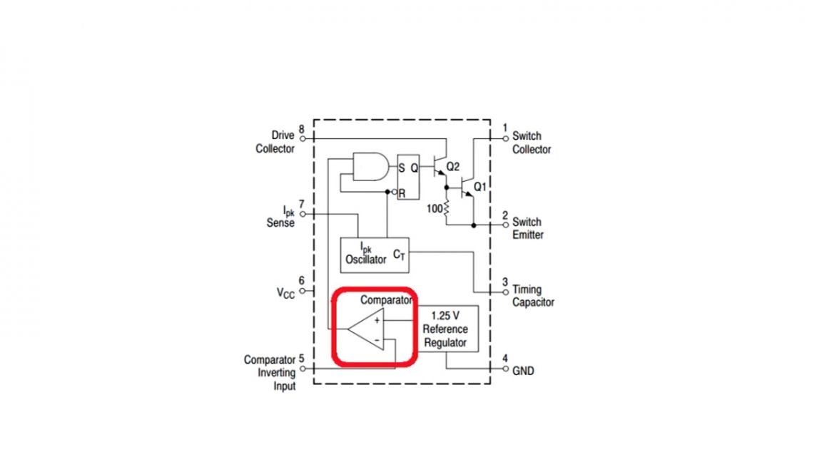
But in fairness it should be noted that at a current of 1A, the microcircuit is already starting to heat up very much. This microcircuit has internal comparators and its own reference voltage source, which makes it possible to organize voltage feedback, or in other words, to stabilize the output voltage at the desired level.
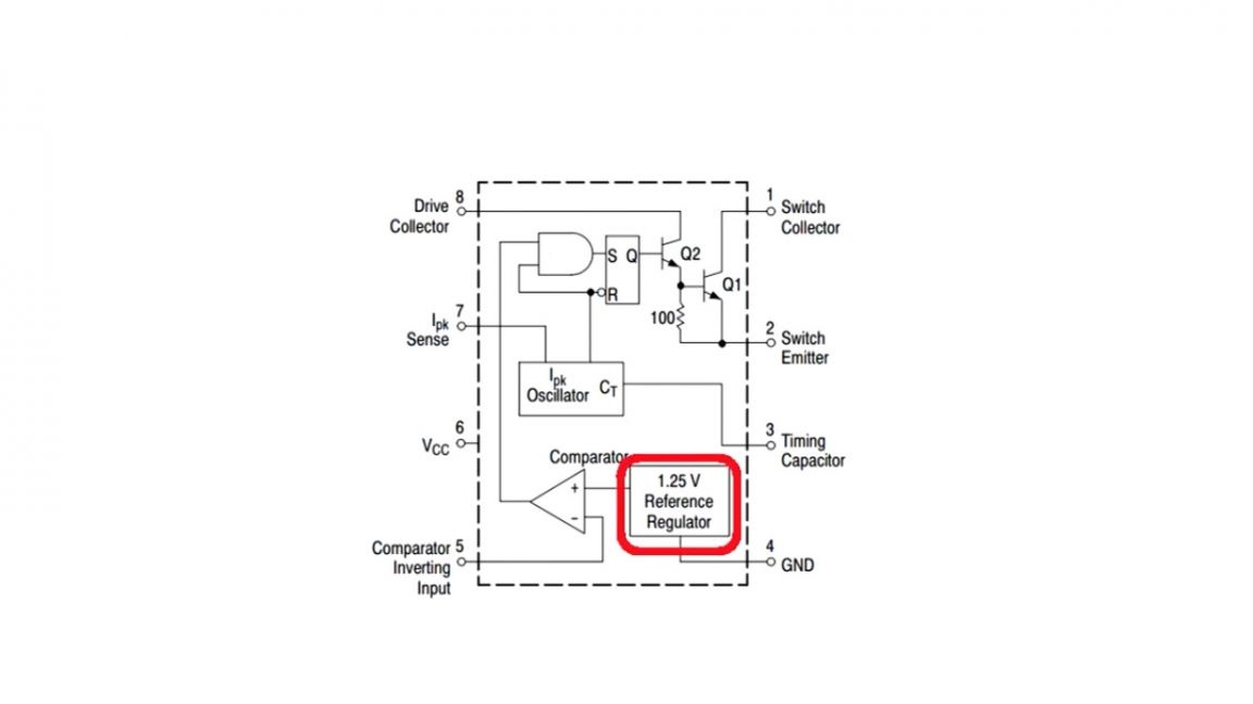
The output voltage will depend on the ratio of the resistances of the voltage divider.
The microcircuit has a lot of goodies, which we will talk about another time, but today we will consider a boost converter circuit.
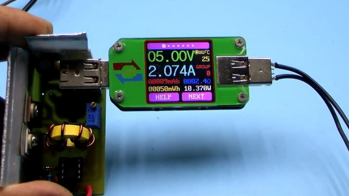
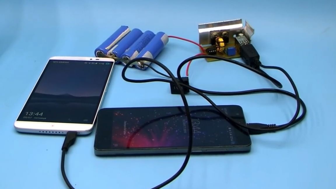
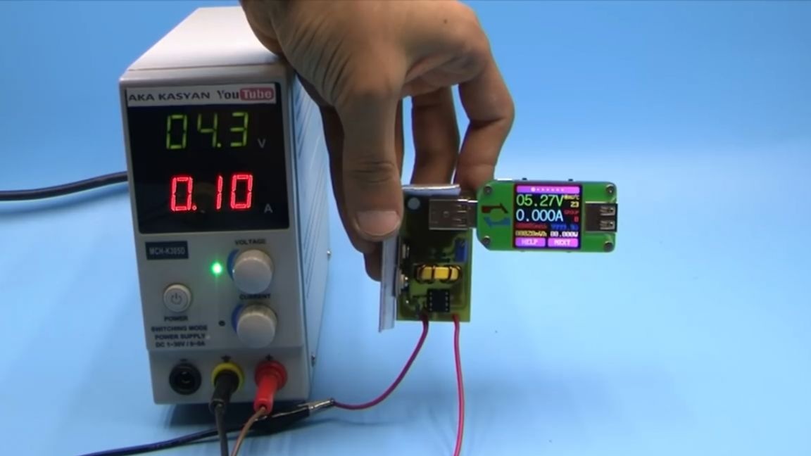
This converter is quite simple and will allow you to charge your smartphone from, for example, lithium batteries.
But there is a drawback - efficiency. The fact is that despite working in a pulsed mode, with such a ratio of input and output voltage, the efficiency of the converter is very small and amounts to 60-65% at best, and this is not good for a portable device.
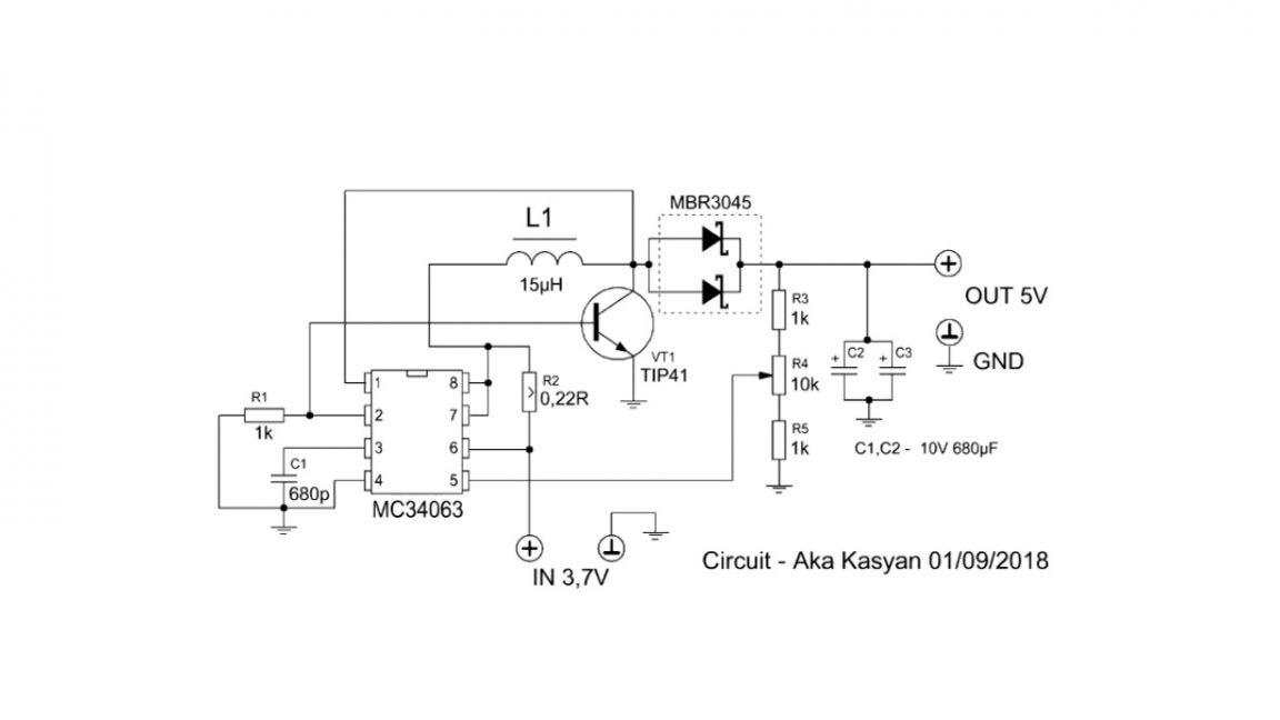
The chip of this circuit is that the output of the microcircuit is amplified by an additional transistor. In our case, it is bipolar.
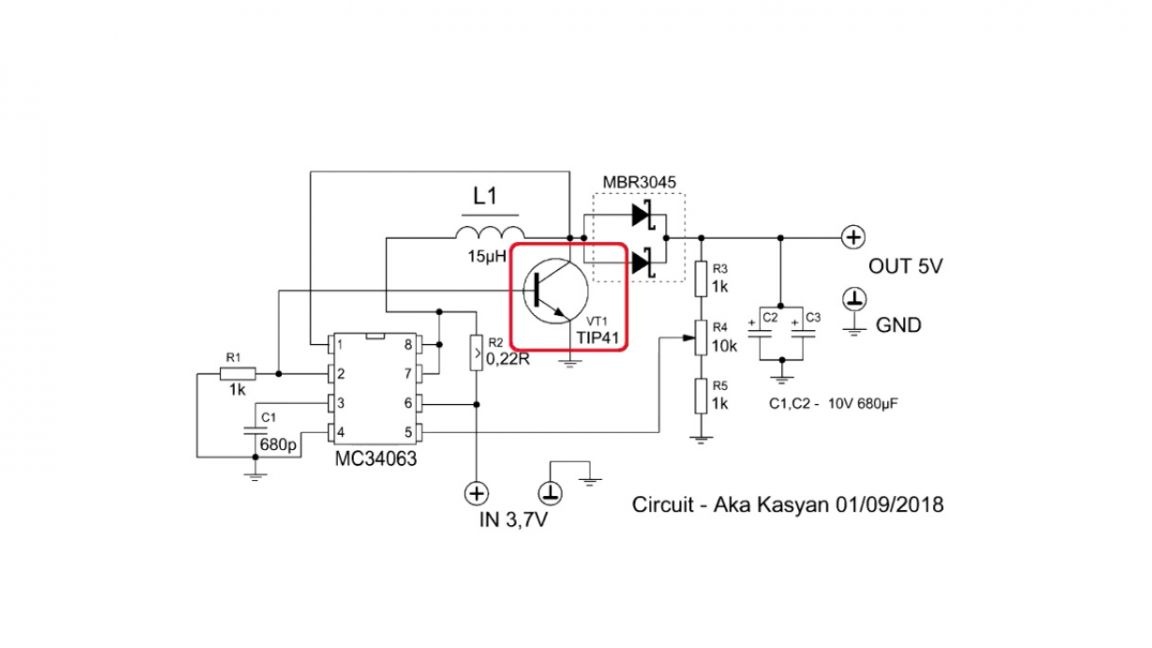
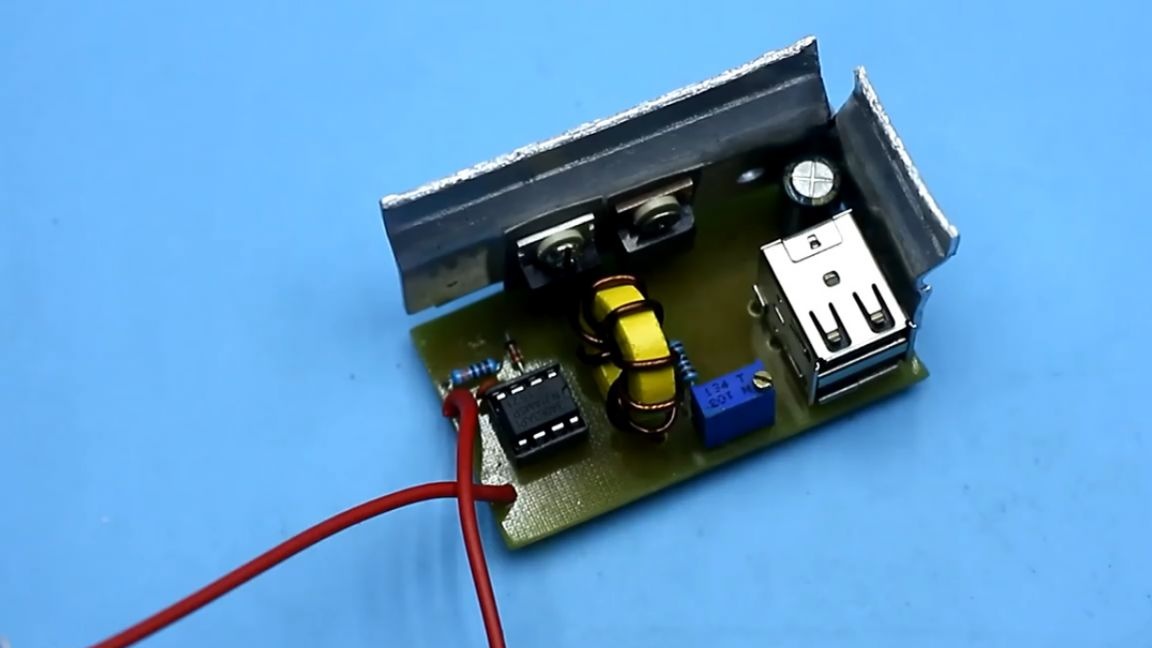
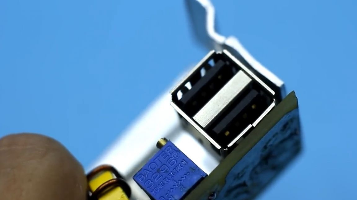
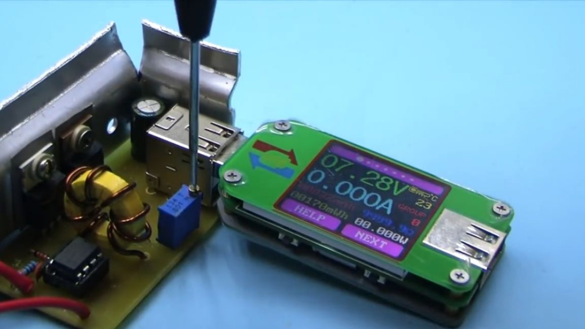
This will improve the output characteristics of the converter and offload the chip. In other words, the circuit will allow the construction of converters for high power.The mc34063 chip starts to work with an input voltage starting from 3V, that is, the above circuit can be used as a boost converter in a home-made power bank. Therefore, the author has a dual USB port on the board.
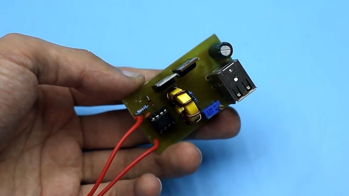
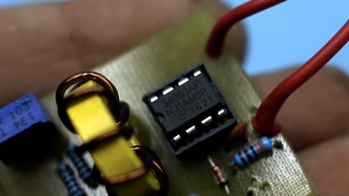
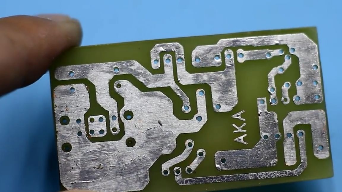
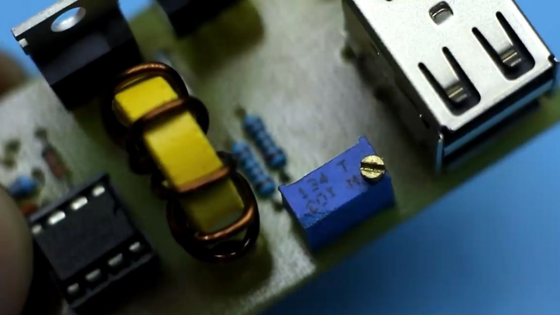
Now about the circuit board. Initially, the author developed the board for a different circuit with a field effect transistor, but the hope was not justified. With bipolar transistors, the circuit works better. The board came out pretty good, with factory quality it certainly can not be compared, but for home technology is not bad at all, and if you want your homemade products to look like a factory product, then you can order a printed circuit board.
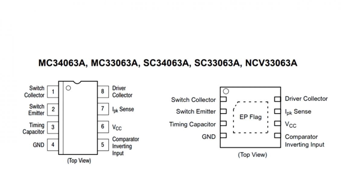
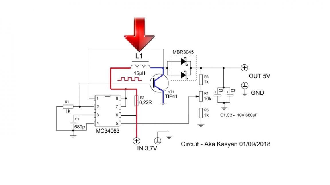
Move on. We will not delve deeply into the operation of the dc-dc converter. But this chip is slightly different from ordinary PWM controllers. The microcircuit generates a sequence of rectangular pulses that enter the base of the key, and it works, closing the power source to the inductor. As a result, energy accumulation occurs in the latter. Then the keys are closed, the surge in self-induction voltage from the inductor is rectified by the diode and accumulates in the capacitor, and from the capacitor is already going to the consumer.
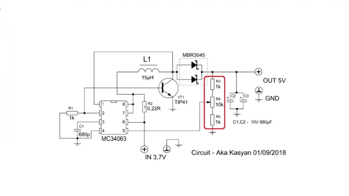
The resistive divider generates a certain voltage, which is applied to one of the inputs of the internal comparator of the microcircuit. There, this voltage is compared with the voltage of the reference source. Based on the voltage difference, the microcircuit increases or decreases the pulse duration and frequency, and the frequency too, since the microcircuit simultaneously controls both the PWM (pulse-width modulation) mode and the PFM (pulse-frequency modulation) mode.
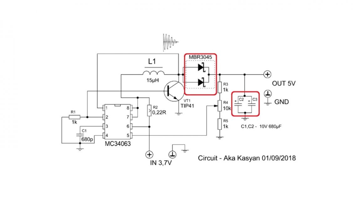
The principle is clearly visible on the oscilloscope screen:
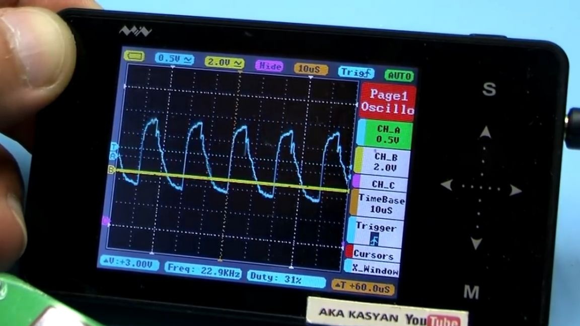
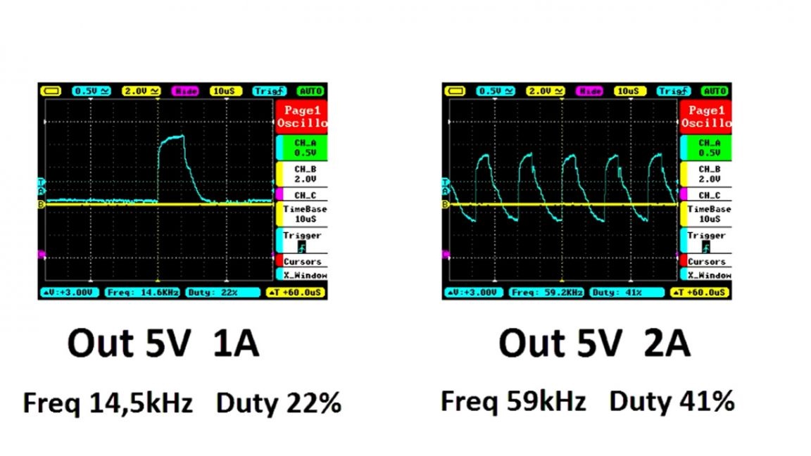
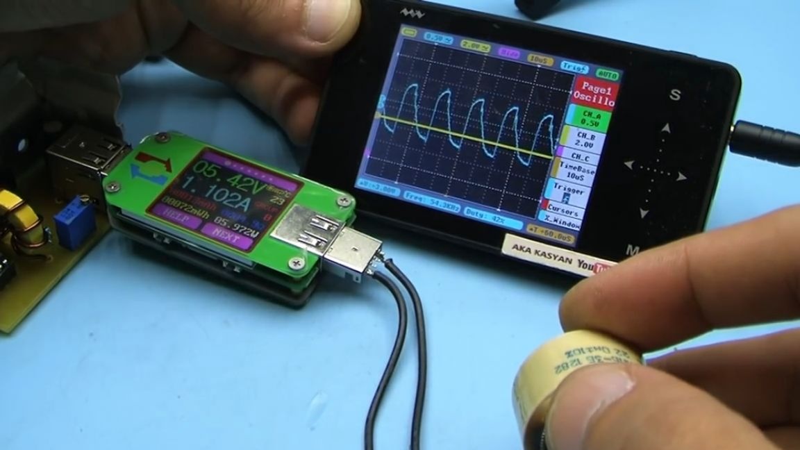
The more powerful the load, the greater the drawdown of the output voltage. A feedback system responds to this, and the microcircuit increases the pulse duration and key switching frequency.
Output rectifier diode. In principle, any Schottky diode with a current of 3 ex amps is suitable. The author decided to take a dual diode assembly from the output rectifier of the computer power supply. Diodes are in parallel.
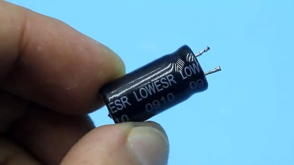
We take storage capacitors at the output with a rated voltage of 10-16V. It is highly advisable to use capacitors with low internal resistance, they can also be found in computer power supplies.
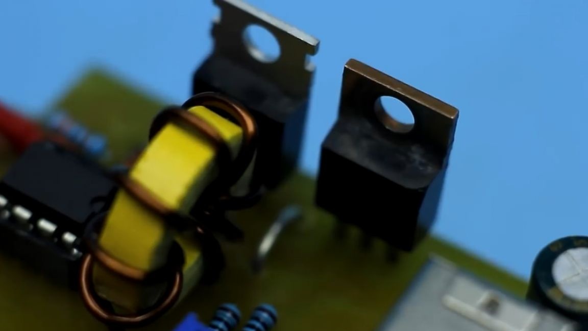
The inductor is wound on rings of powder iron, not ferrite, namely powder iron.
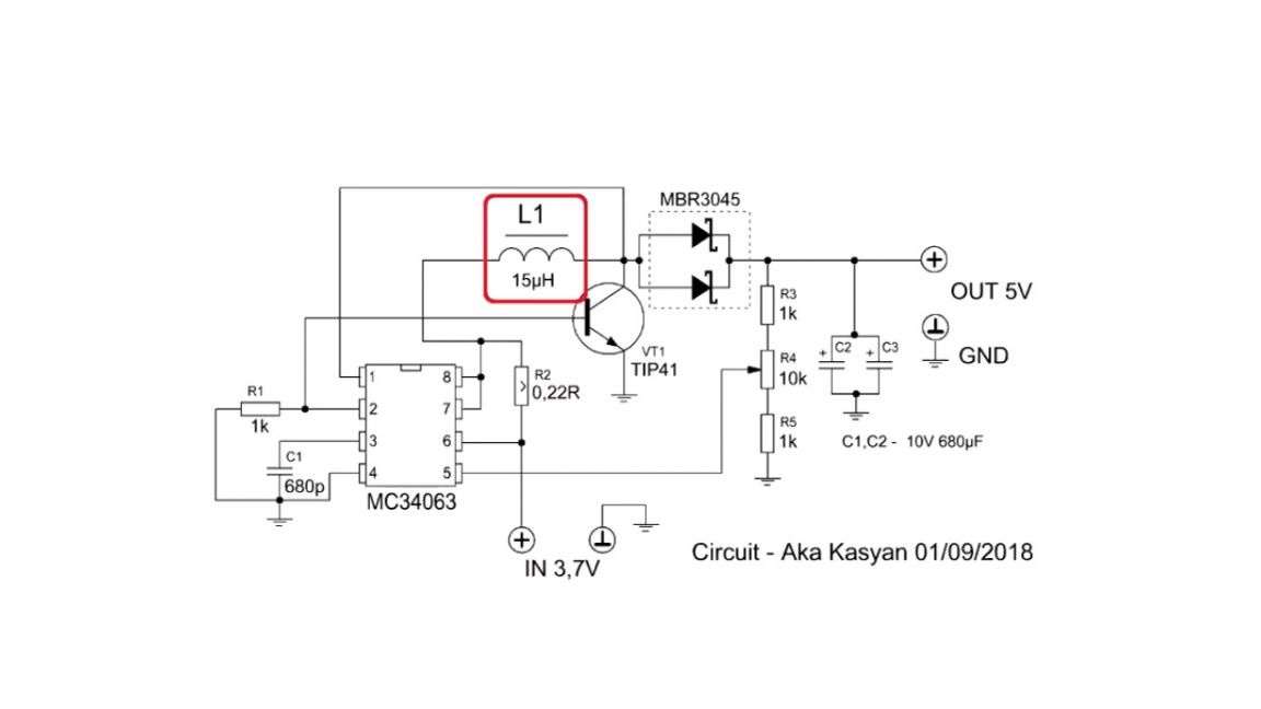
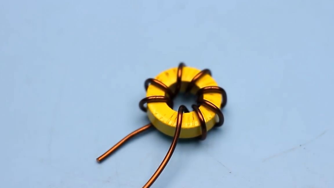
Ferrite ring is not suitable here. The ring size is now in front of you:
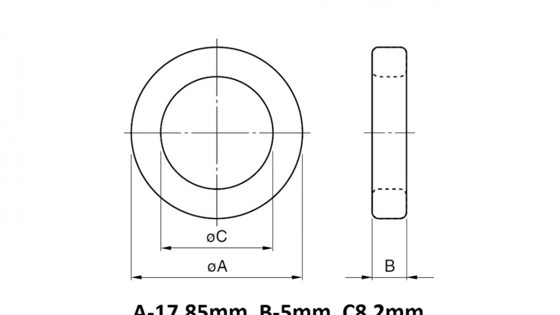
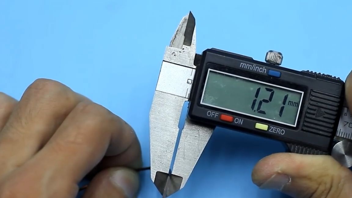
The winding contains only 6 turns, wound with a 1.2mm wire, and can be millimeter.
It was with this inductor that the maximum EMF of self-induction reached 20V. So thanks to the tuning resistor, which, by the way, is provided on the board, it is possible to adjust the output voltage over a fairly wide range.
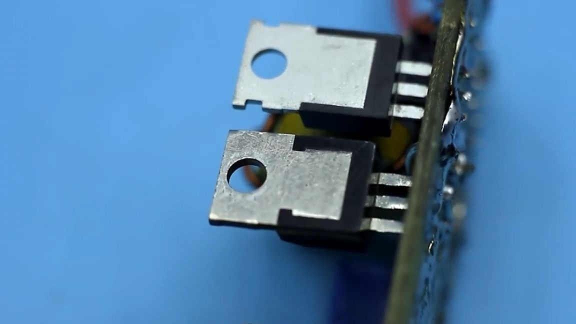
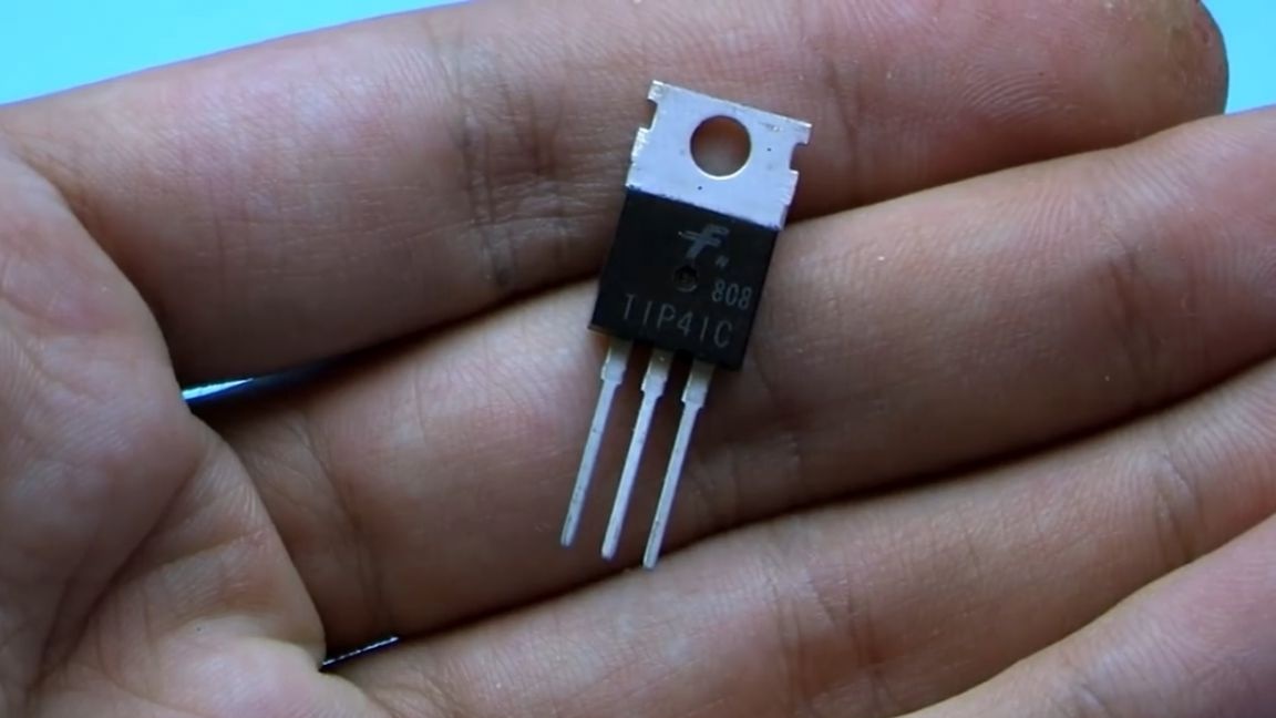
The author put the transistor TIP41, as the most affordable option. The collector current is only 6A, if possible, put keys with a collector current of 10 amperes or more. But even with such a not so steep transistor, it is possible to obtain a current of about 2A at the output of the converter.
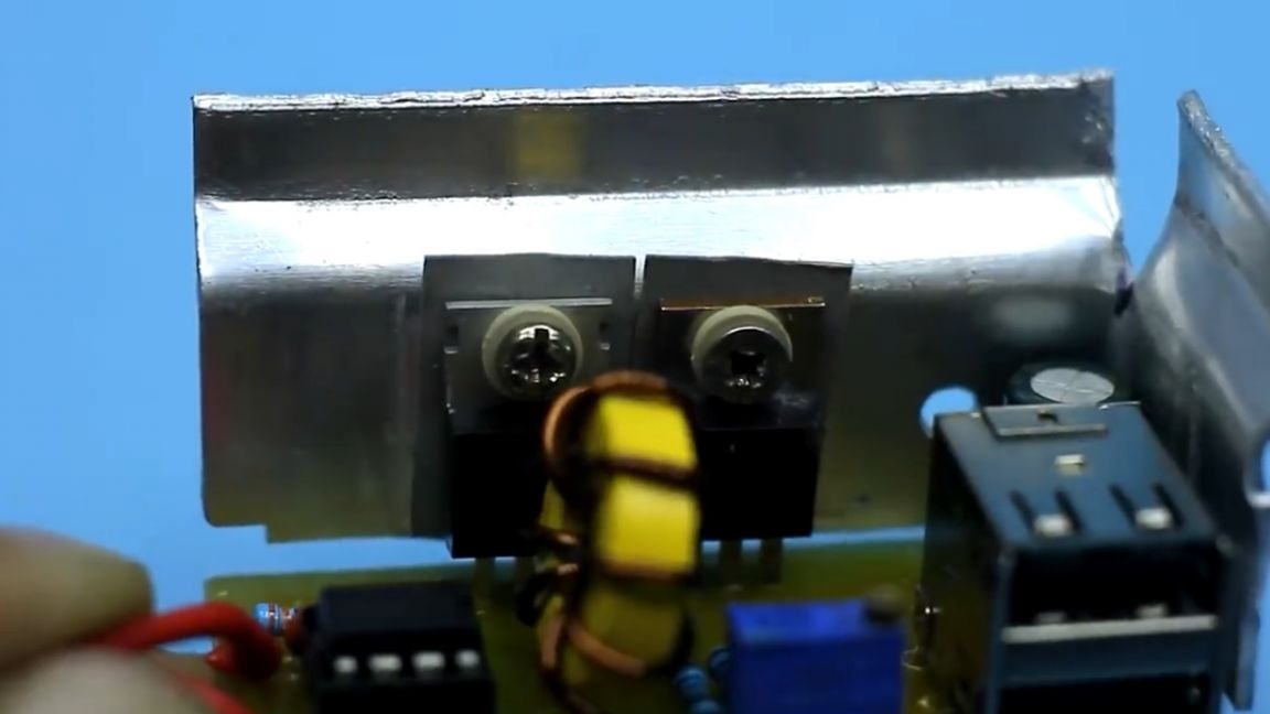
Naturally, the transistor heats up, so both the key and the diode are installed on a common radiator. Do not forget to isolate the substrates of these components from the radiator with heat-conducting gaskets.
The current shunt can be excluded from the circuit if protection is not needed.
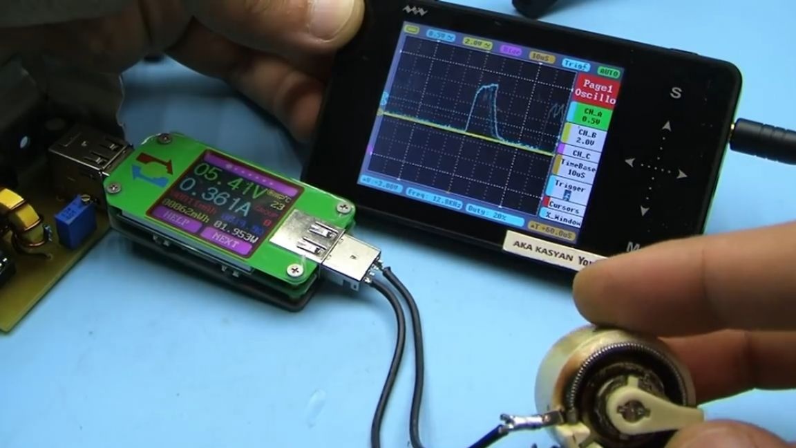
One of the advantages of this circuit is the meager idling current (less than 10 mA). The indicated 2A output current is not the limit for such a circuit. It is possible to pump out even more, but there is no sense in this because of the low conversion efficiency.
That's all. The archive with the circuit and the printed circuit board can be found in the description under the original video of the author (link SOURCE).
Thank you for attention. See you soon!
Video: