
This article will discuss how to properly wind a pulse transformer.
The author of YouTube channel “Open Frime TV” Roman, recently assembled a switching power supply on an IR2153 chip, and now he will tell you how to wind a switching transformer for a home-made power supply yourself.
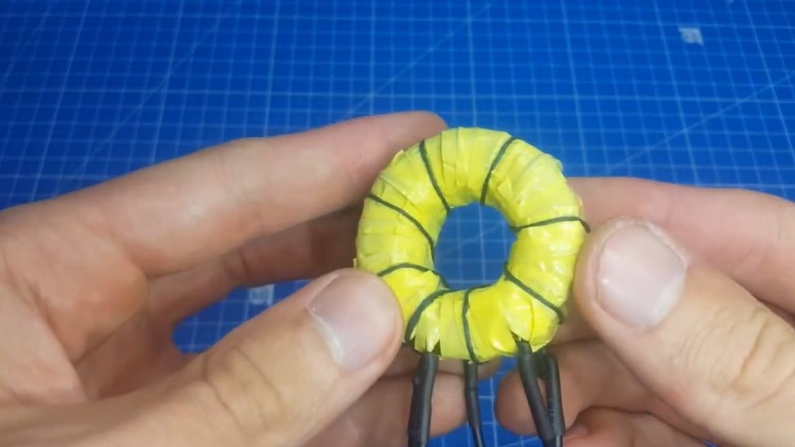
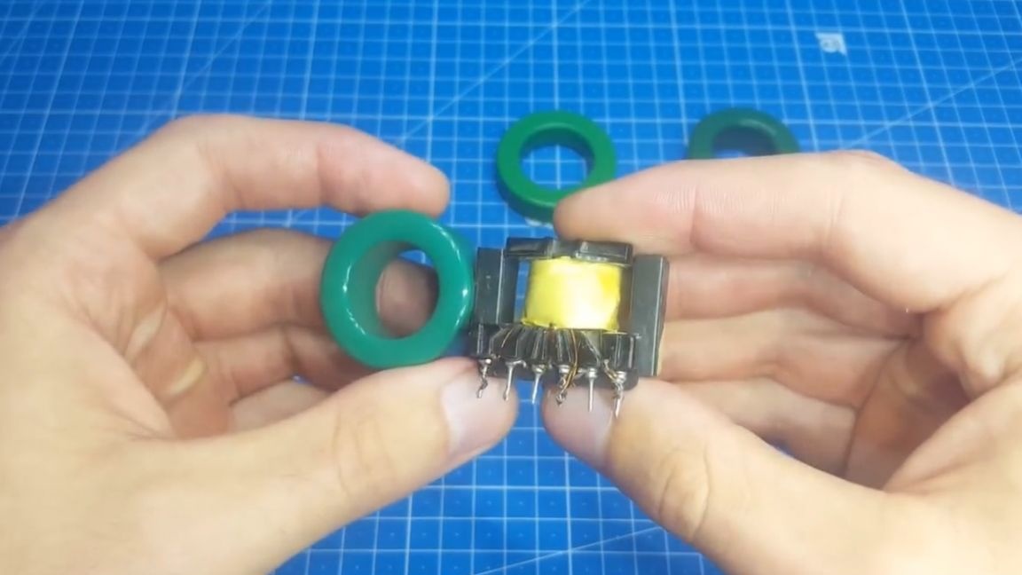
It so happened that the first transformer wound by the author was on a ferrite ring, and after that he could no longer wind on w-shaped ones, and there were several reasons for this. The first is a relatively small place for winding w-shaped cores, while for toroidal cores, it can be stretched along the entire ring. And from here a second problem appears, if many turns are wound, then it is difficult to close the halves of the core.
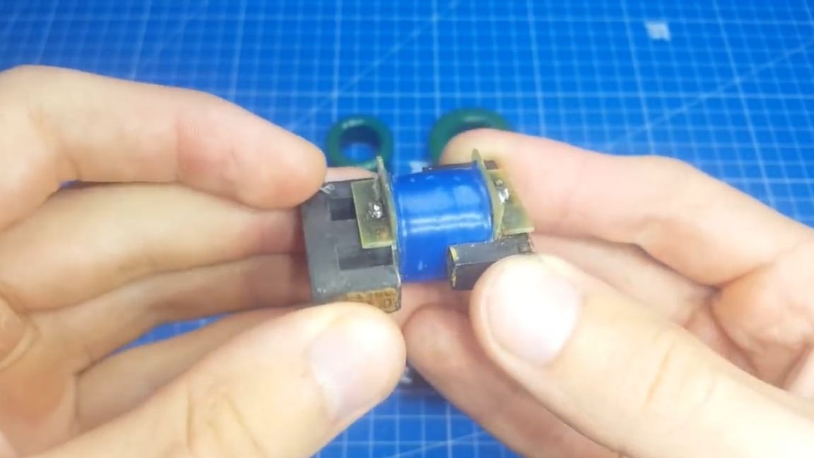
Yes, you can say that the reverse side of the coin will be the prevalence of such cores in computer power supplies, but you should try to disassemble the core normally without breaking it. Although it has already been experimentally proven that a broken core after gluing works the same as a new one, it’s calmer for the soul when using whole ferrite.
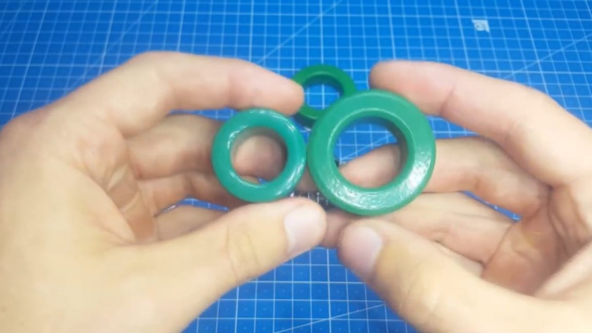
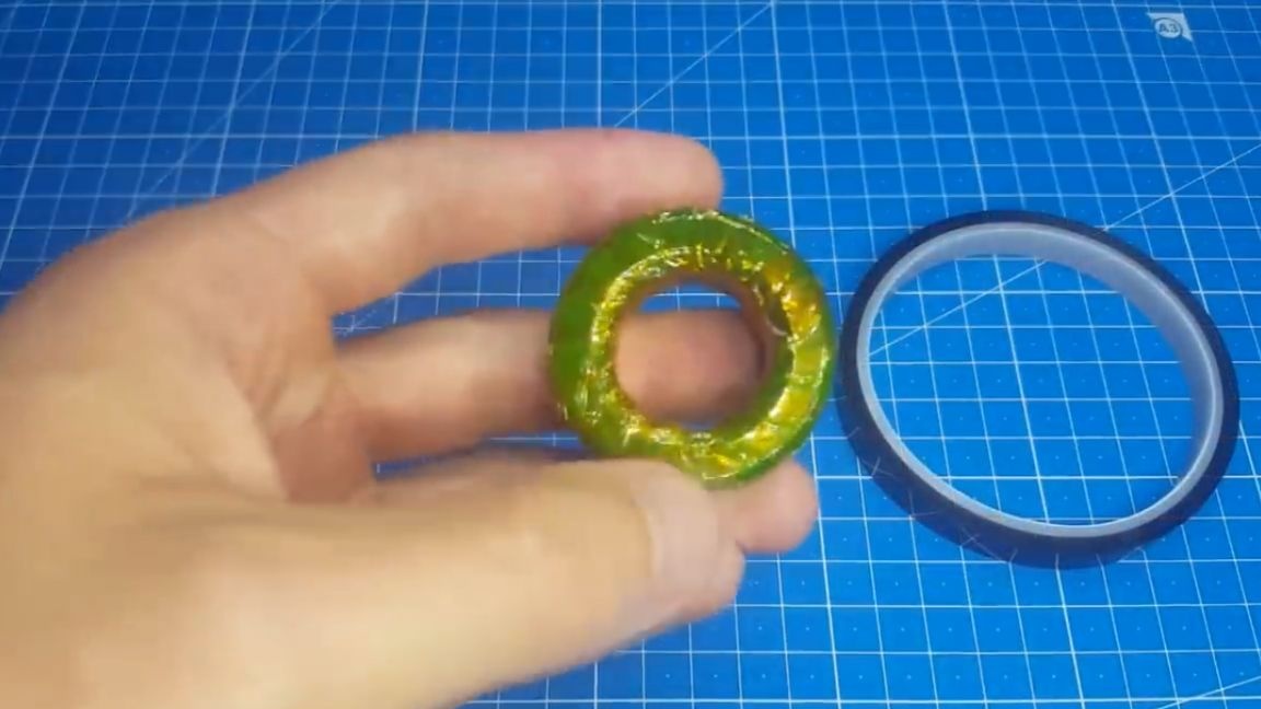
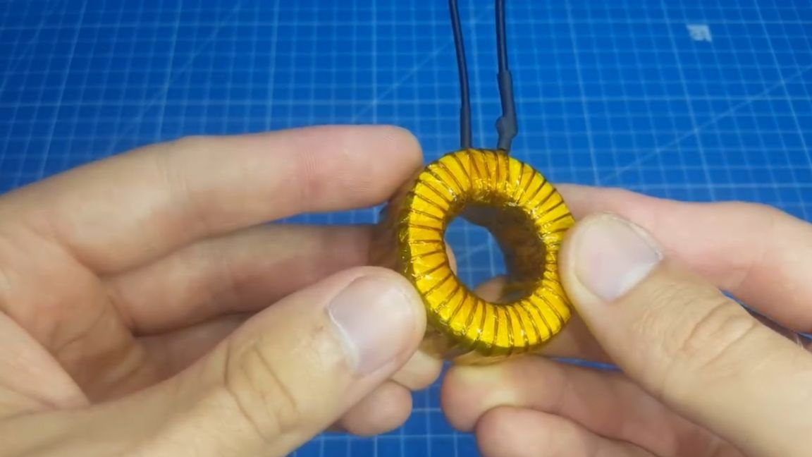
Another, with the same size, the ferrite ring has a greater power than the w-shaped core. For example, a few cores. Sh-shaped can give out power of 150-180W, and about the same size toroid can give out 250W.
For comparison, here is another toroid that is only 1 cm larger than the previous one, and this one can already produce 600W of power.
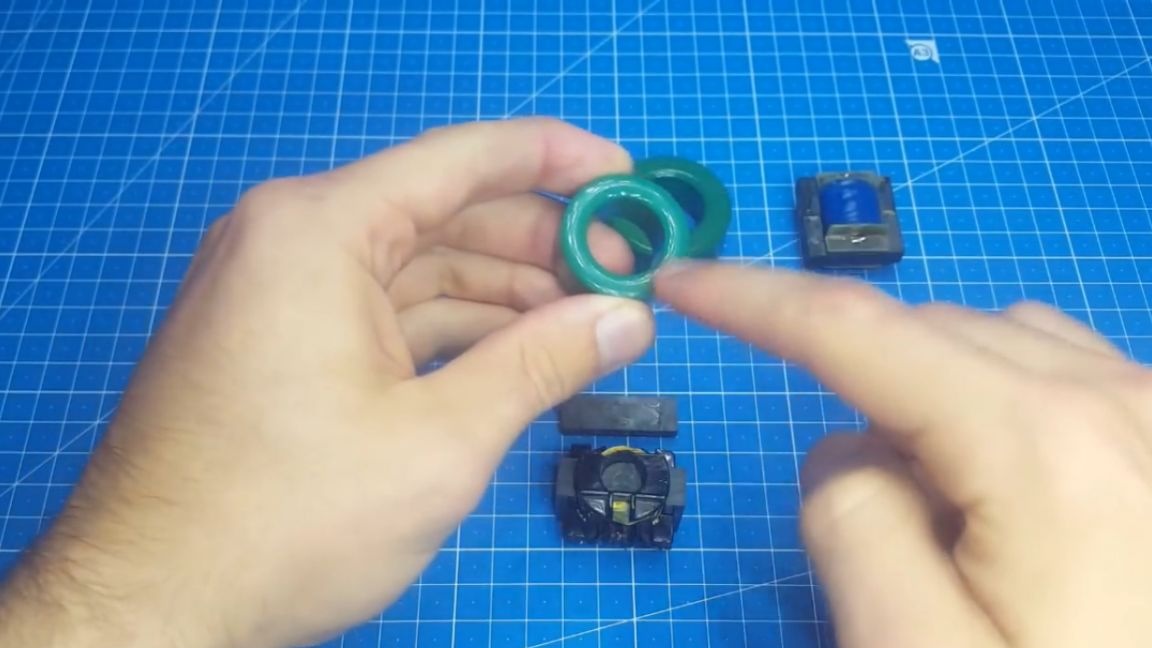
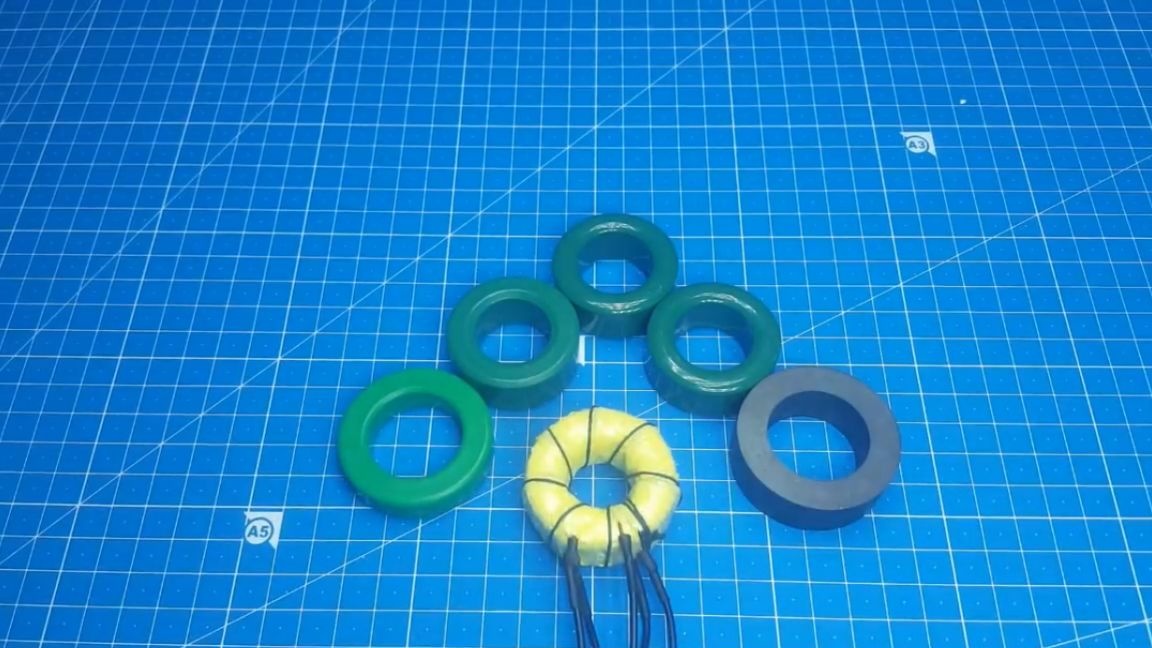
The author hopes that the arguments presented by him were very weighty, and advises switching to winding transformers on toroidal cores. Well, now we turn to the winding. For this we need a core. They come in different types. Here are such, still produced by the USSR and here are those made in China:
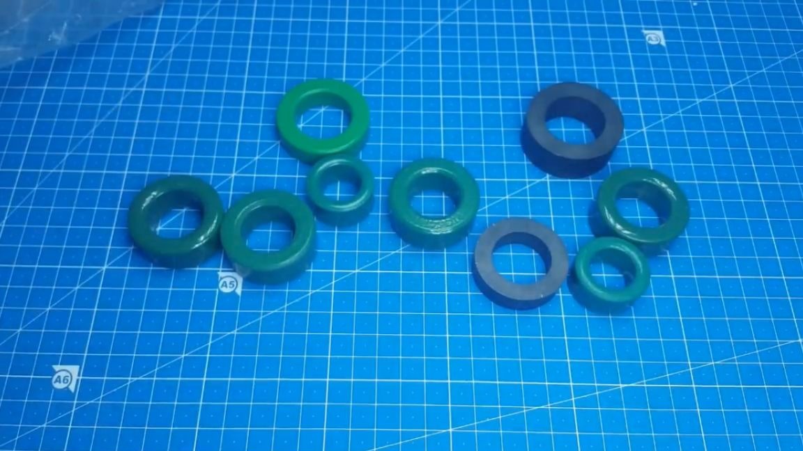
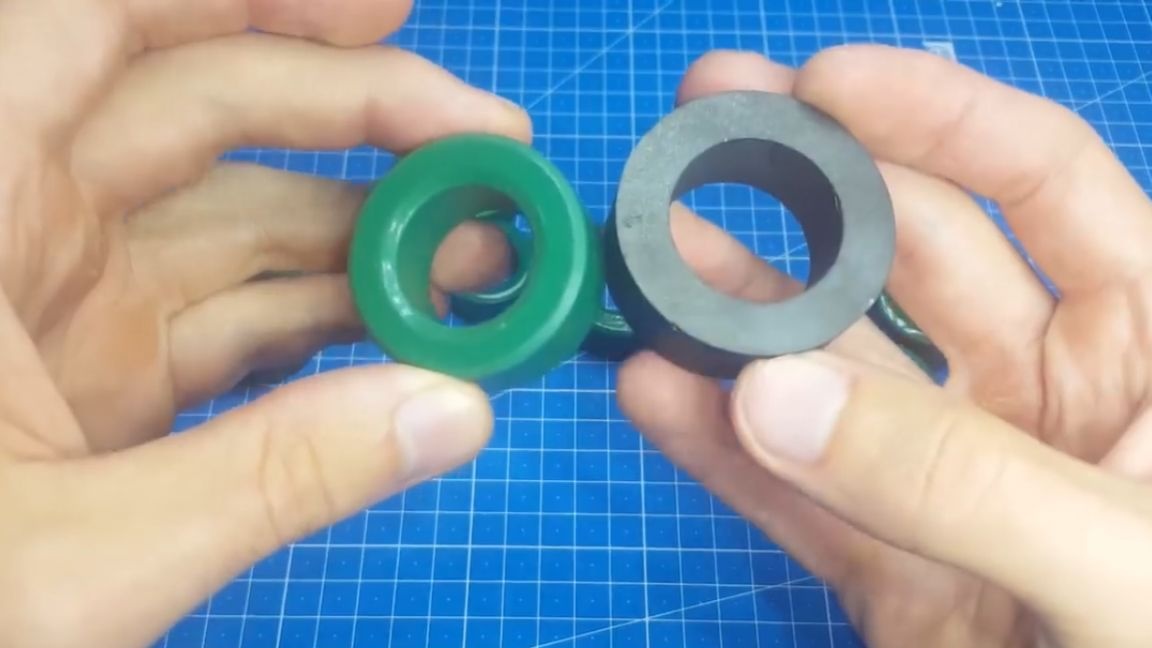
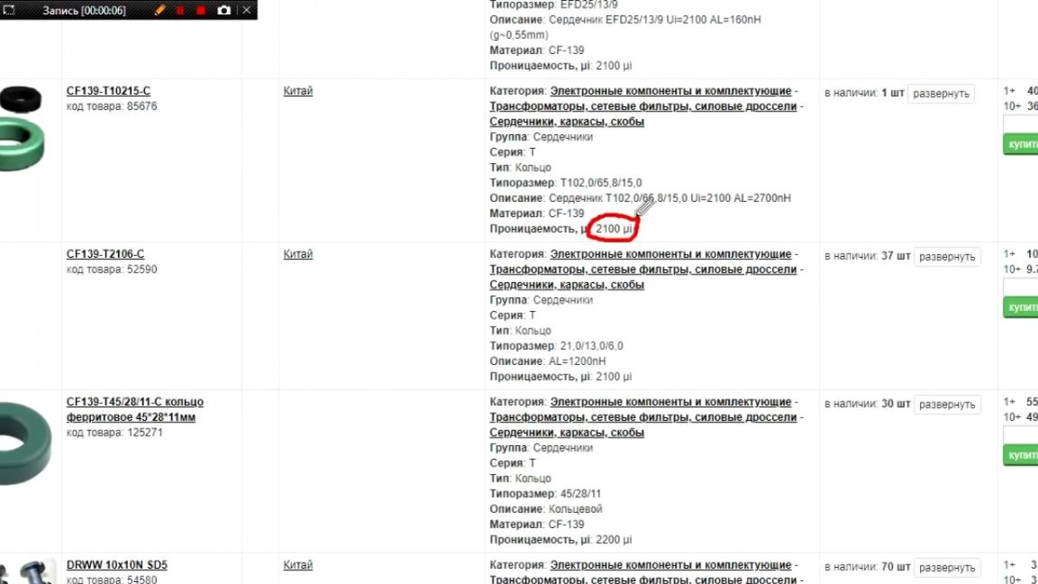
You can use both those and others. The cores made in the Soviet Union should have 2000NM marking, and when choosing Chinese, it is necessary to monitor permeability, it should be in the region of 2000-2200.
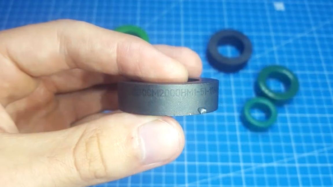
We figured it out, go ahead. As you can see, the Chinese cores are already coated with paint and, in fact, you can wind directly onto the core without insulation.
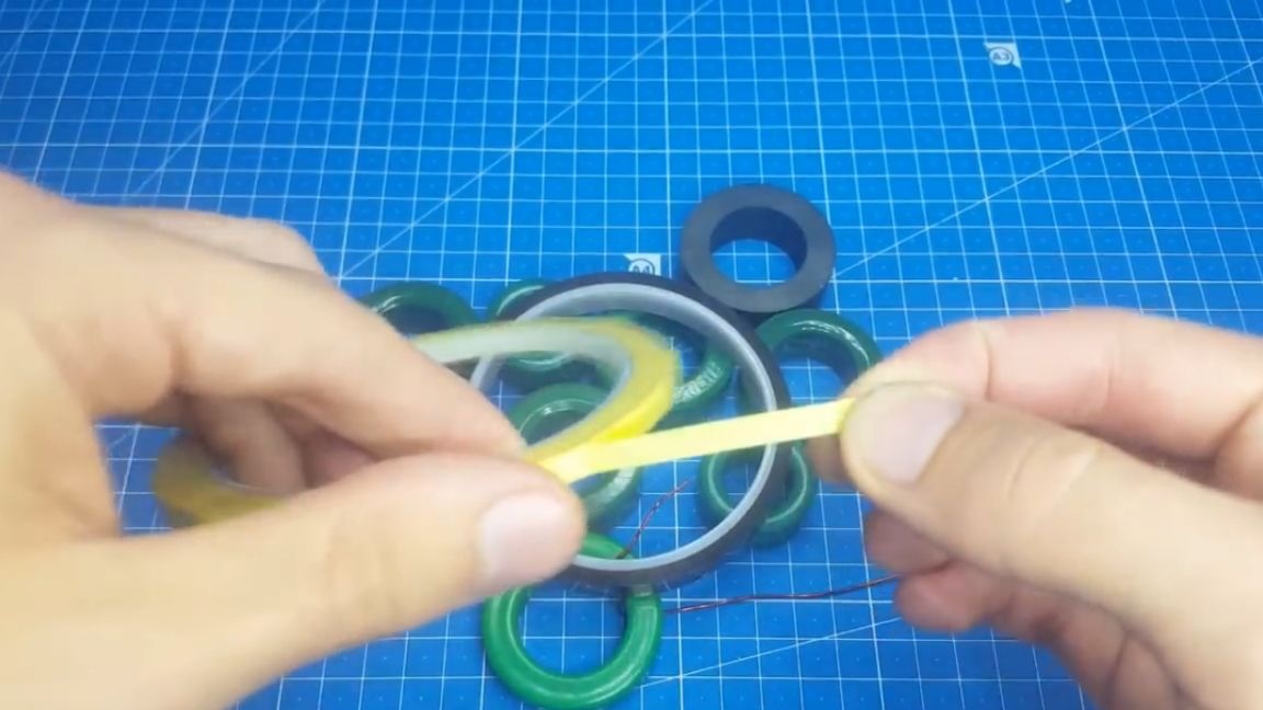
But then the wire will slide over the surface. If you, like the author, are not happy with this, then for isolation you can use just such a yellow high-voltage mylar tape:
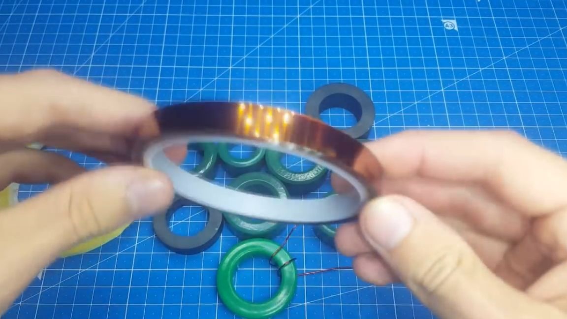
Or you can use this thermal tape:
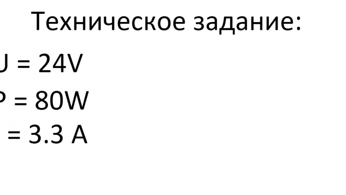
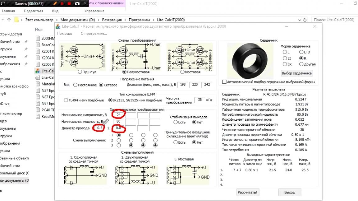
It is extremely undesirable to use the classic blue electrical tape in this case, since it strongly retains heat when heated. Before manufacturing the transformer, you already know what voltage and power it should give out. So the author came up with the following terms of reference: it is necessary to wind a transformer for 24V, 80W for a future project of a soldering station.
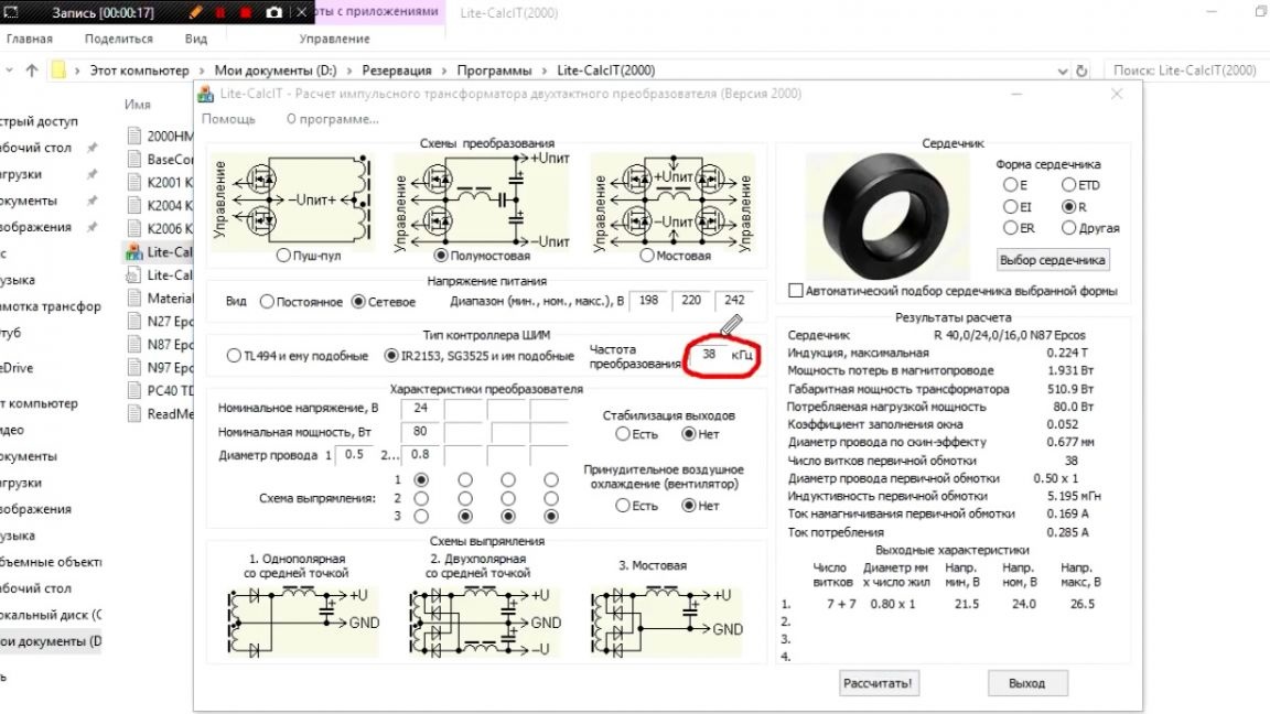
The following program will help us with the calculations:
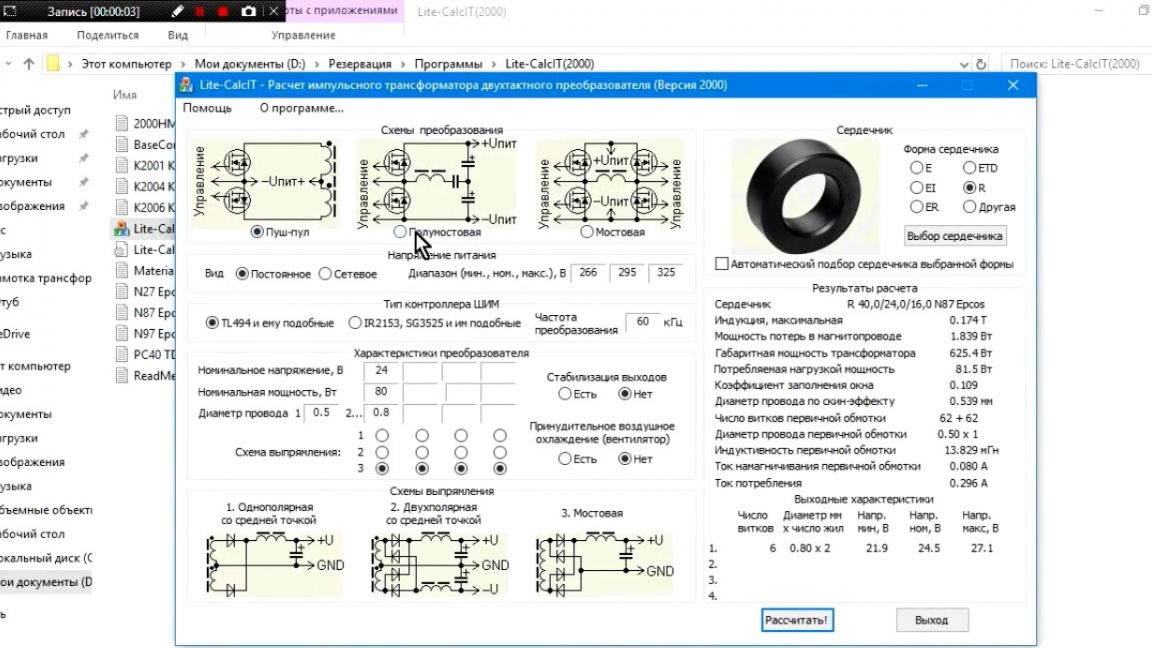
The author left a link to it in the description under the video (the SOURCE link at the end of the article). In the program we enter the necessary value. If you are making a switching power supply according to the author’s scheme, then simply repeat the steps as on the screen (this is shown in more detail in the author’s video at the bottom of the page).
Differences will be in several parameters. The first is frequency.
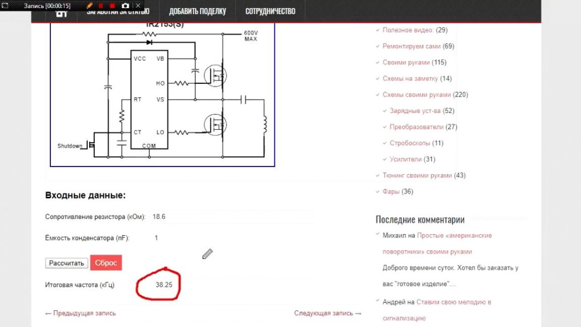
It depends on the value of this resistor:
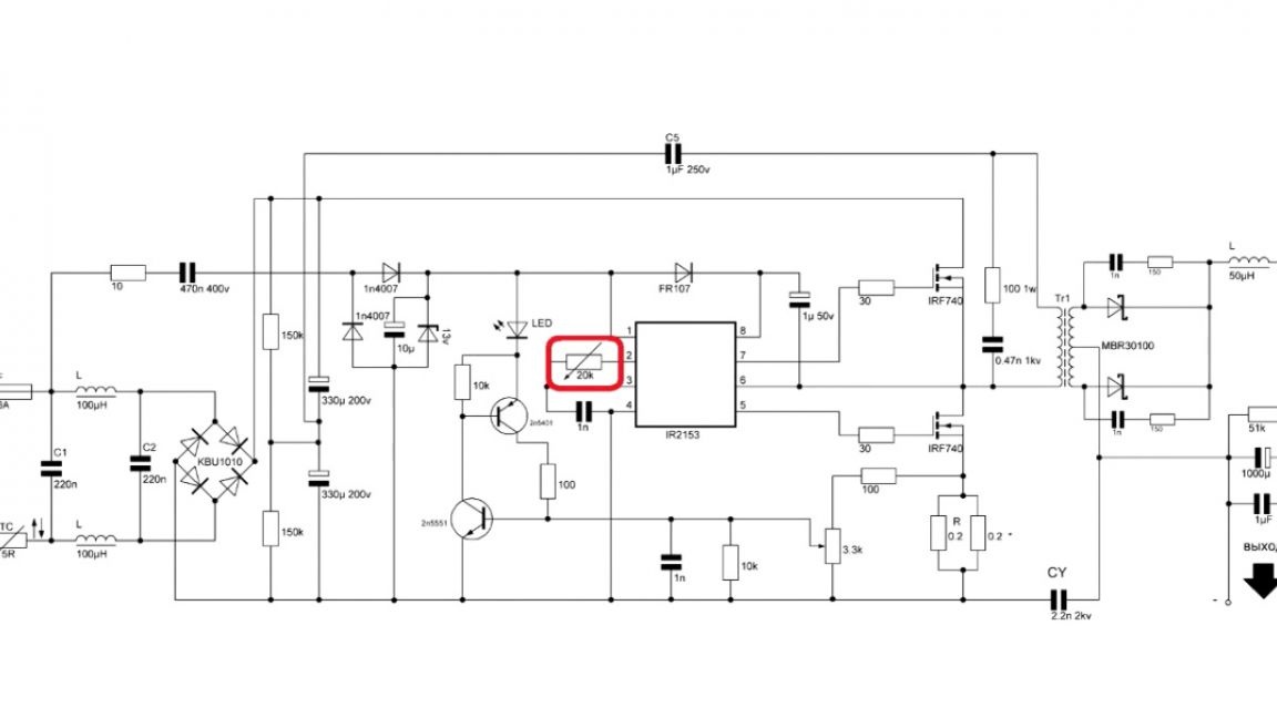
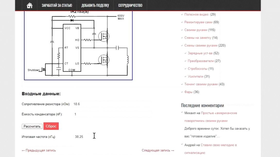
You can calculate it in the online calculator. It is enough to score the value of the capacitor and resistor. At the output, we get the frequency.
You will also have your own output voltages and wire diameters.
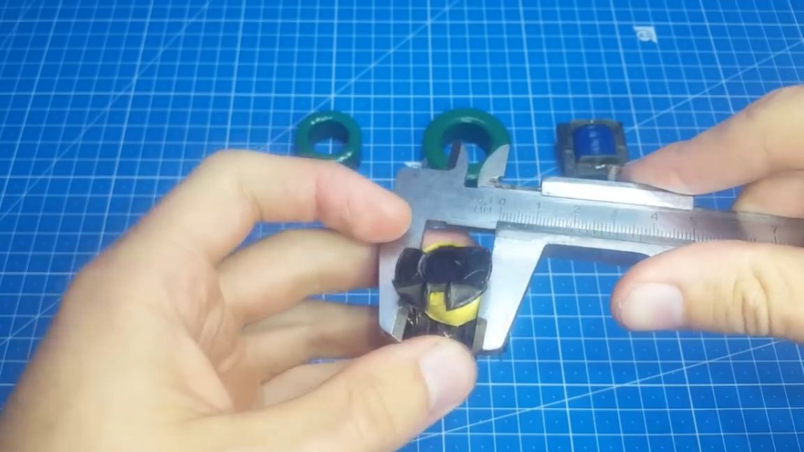
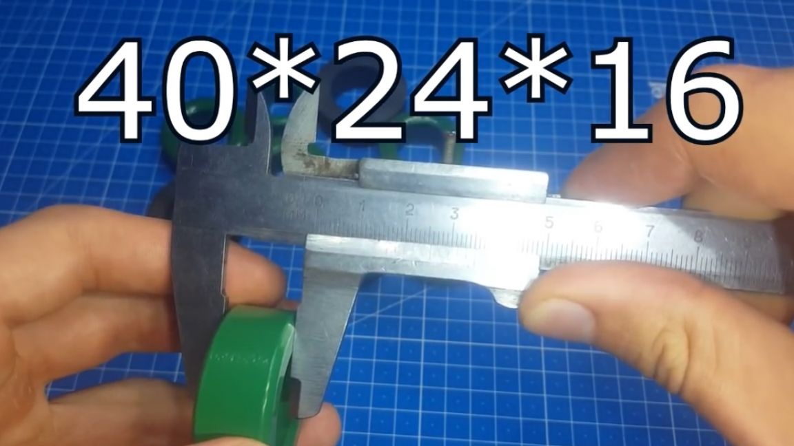
When we figured out the data, we proceed to the selection of the core. If you have cores in stock, then measure their size with a ruler or vernier caliper, and then look for the same size in the program. When you indicate your core, the program will show the overall power, and you already understand whether it is suitable or you need to look for a new one.
If there are no cores available, then just start sorting through different sizes. Thus, we find the desired core, and then it remains only to buy it in the store. I hope you understand the principle of core selection. The author had cores with a minimum power of 250W, they can be safely used. Yes, there will be a small overspending of the material, but this is not scary, it is better to have more power than less.
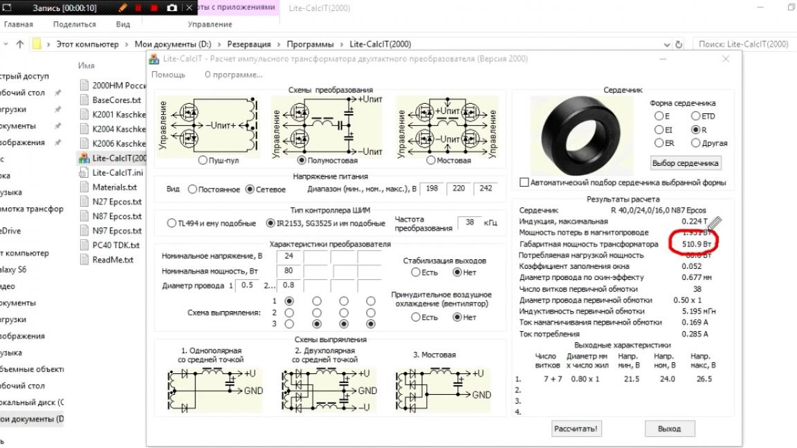
The author decided to use a core with obviously greater power, because the winding process will be more clearly visible on it. When all the data has been entered into the program, we press the “calculate” button, and we obtain the necessary parameters for winding.
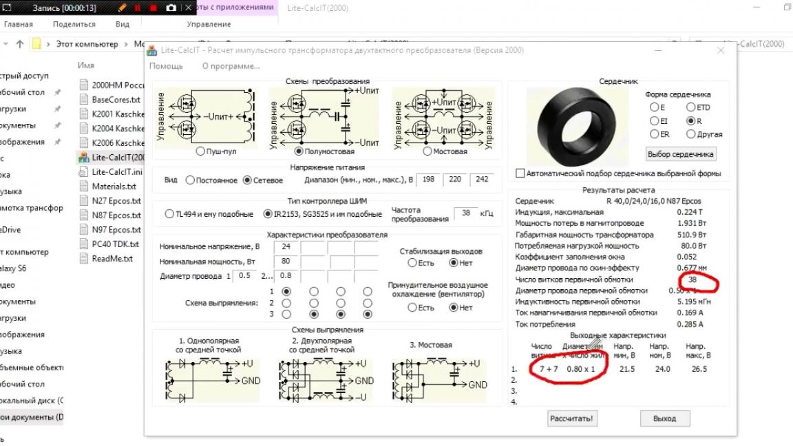
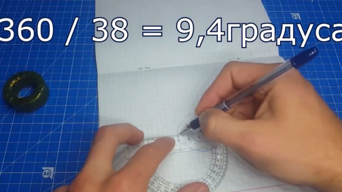
As you remember, we need to get a 24V voltage at the output, but according to calculations it turns out 26V. In this case, you can change the frequency and look for a value at which the desired voltage is output. Together with the change in frequency, the parameters of the winding also change. For example, we found a frequency of 38 kHz, at which the output voltage is exactly 24V. We go to the online calculator, and changing the value of the resistor, we find the value at which the desired frequency is 38 kHz, and then directly when the resistor is soldered onto the board, we set the desired value on it.

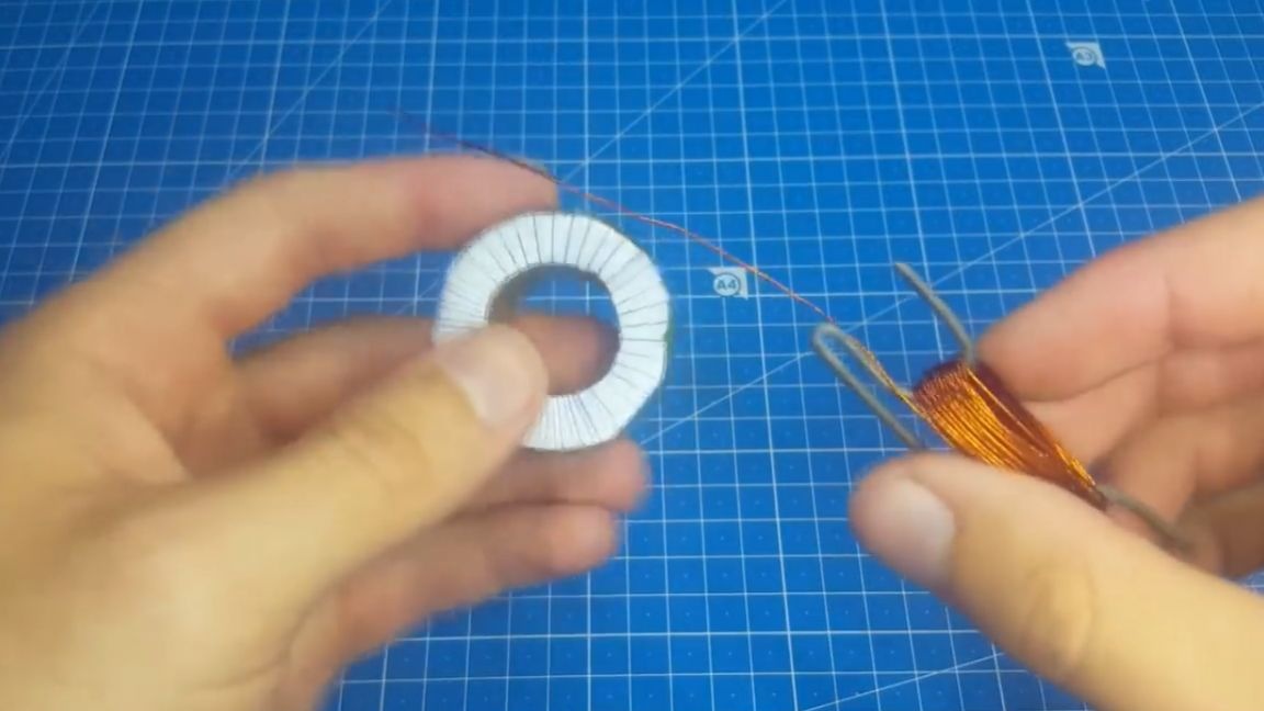
You can go to the winding. Isolate the core.
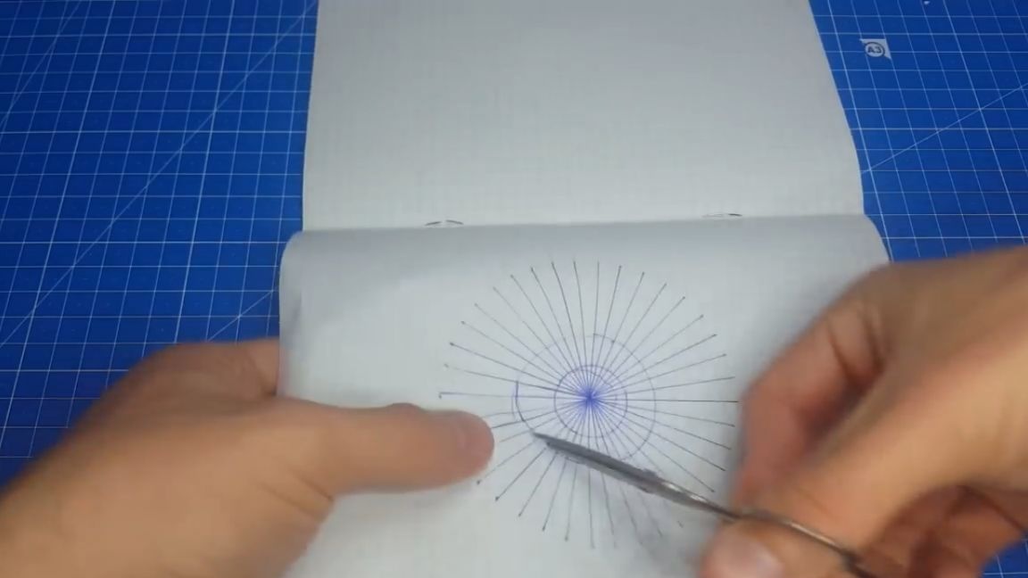
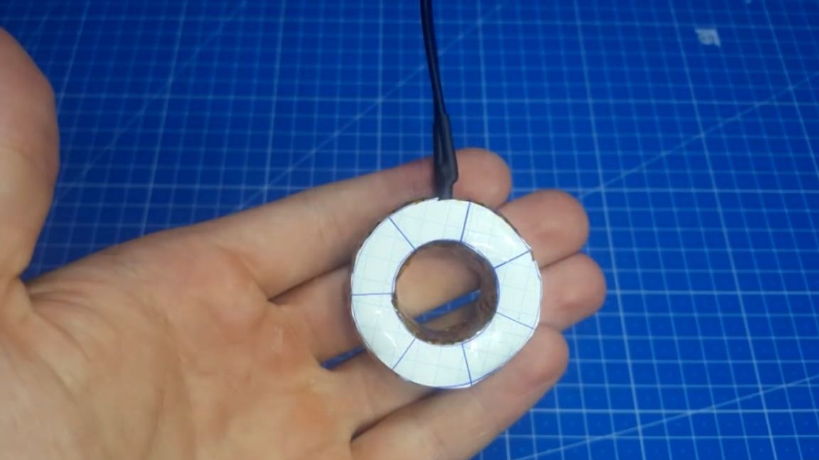
Now you can wind the primary winding, but it will be difficult to evenly distribute it to the eye, so we will make the markup. We need a leaf and a protractor. We make 2 diameters: internal and external. We set the starting point and using the protractor we divide our markup by the number of turns needed. Then we cut it out, and with the help of adhesive tape we glue it on the core.
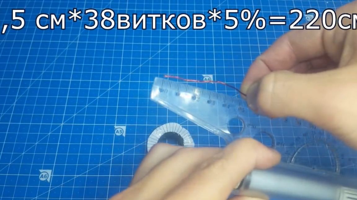
Next, you need to rewind the required length of wire for winding. This can be done by knowing the length of one turn, as well as the number of turns. We measure one turn and multiply by the number, and also add 5% due to the fact that the wire does not lie on a turn to the turn, but is slightly stretched, and conclusions must also be drawn.
When they learned the length of the wire, we unwind it, cut it off and you can wind it. For this, the author uses this device:
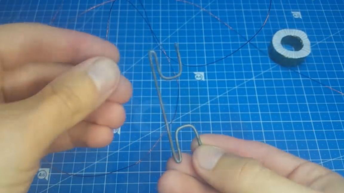
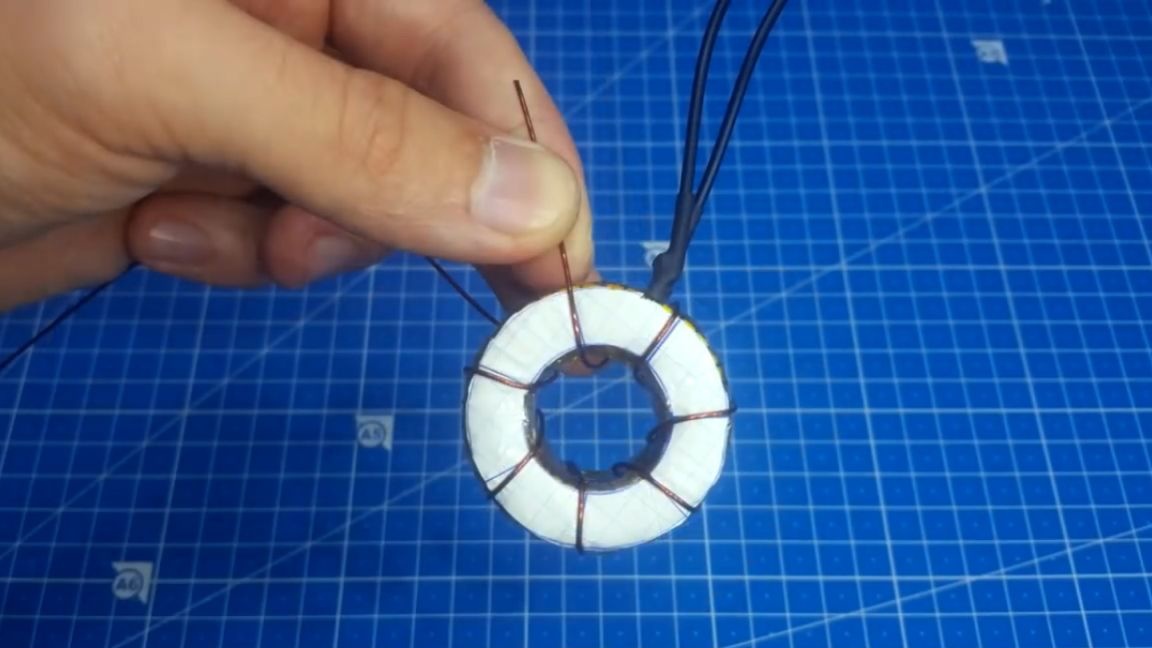
A wire is wound around it and then quietly threading it into the core, it is wound strictly according to the marking. To fix the coils, you can use superglue.
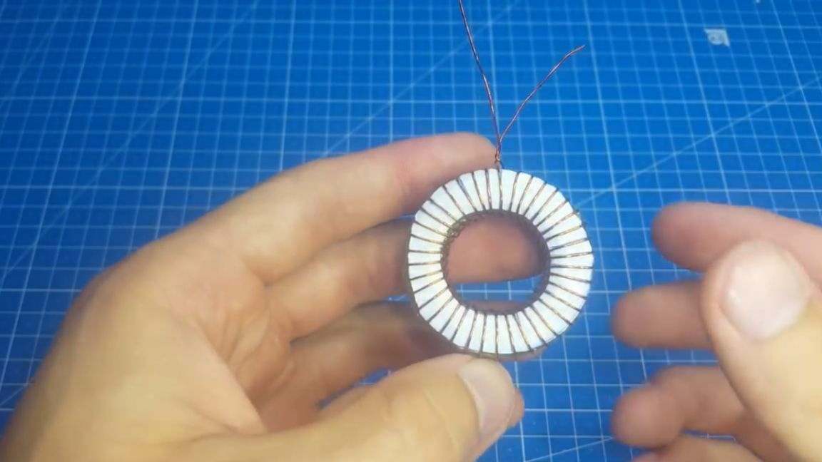
Now it remains to solder the stranded wire to the primary and insulate it with the same thermal tape.
That's all - the primary is ready, proceed to the manufacture of the secondary. The winding direction of the primary and secondary may not coincide - it does not matter. The secondary winding procedure is practically no different from the primary winding, the same marking, the turns are really less, but the process is identical.
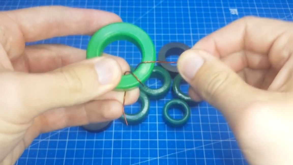
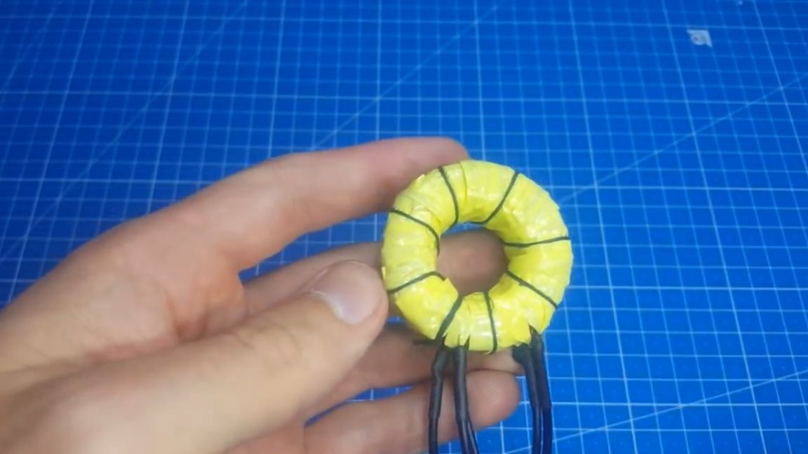
And now the most important thing. This is where most people get confused, this is how to make the middle point. So, now the author will demonstrate this as clearly as possible. So we wound one half of the secondary - this will be the middle point.
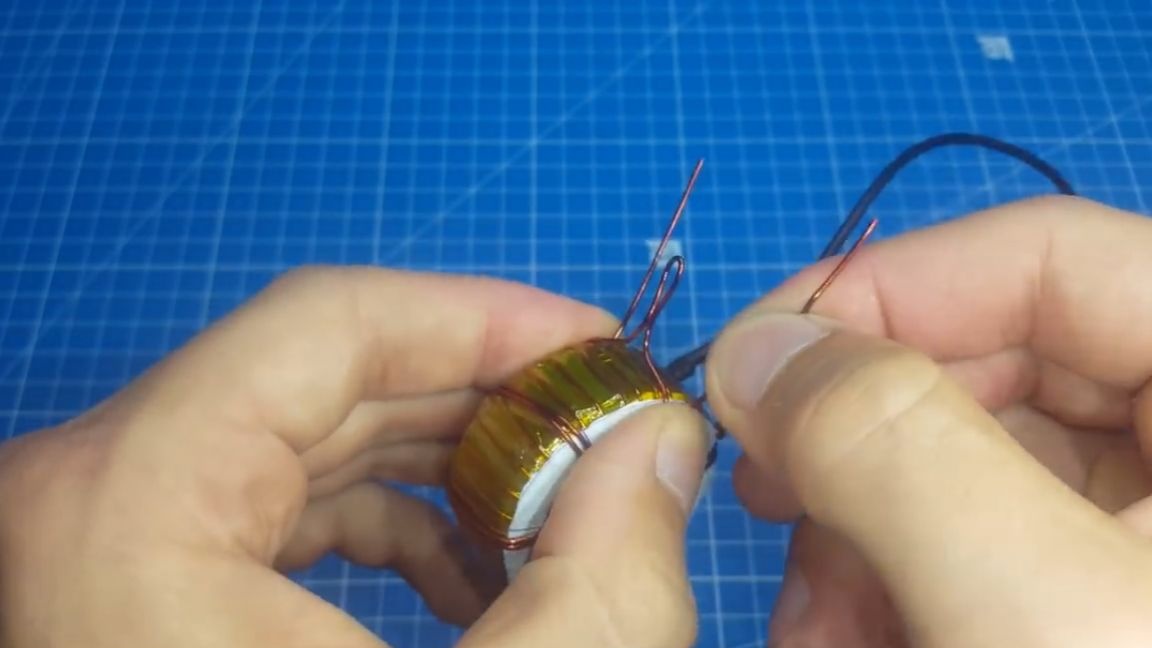
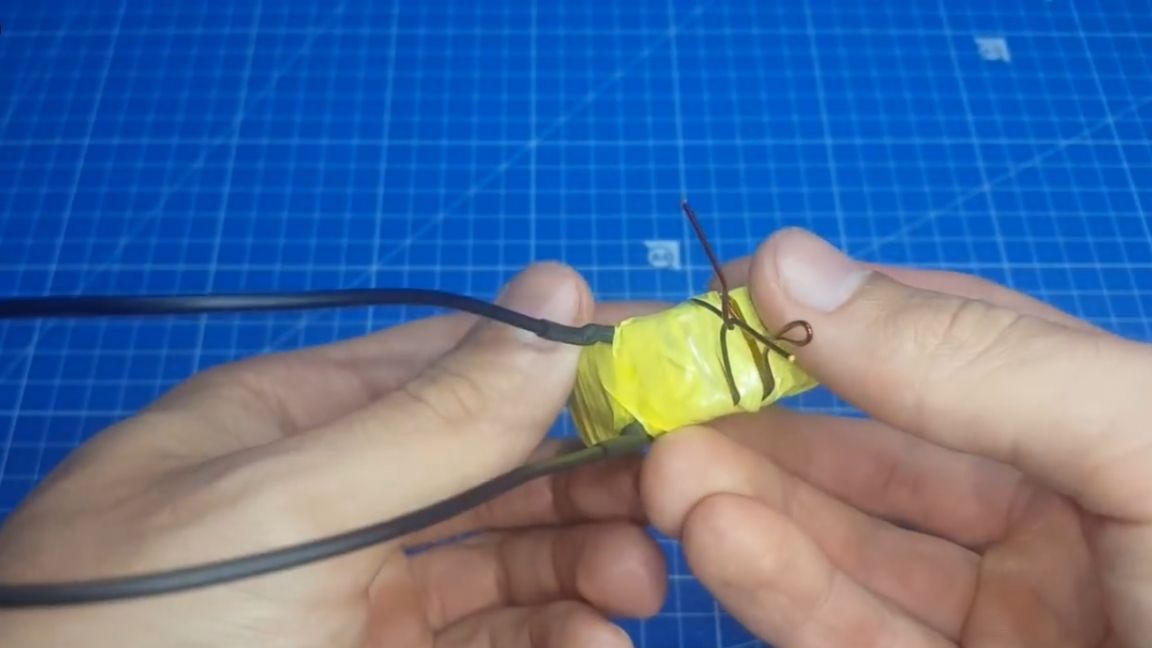
The author intentionally does not cut the wire, but I am doing just such a loop. Now we continue winding. We lay the wire round to round to the previous winding, while maintaining the direction of winding. Now we have 3 conclusions. Where one wire is the beginning and end of the winding, and the loop is the middle point.
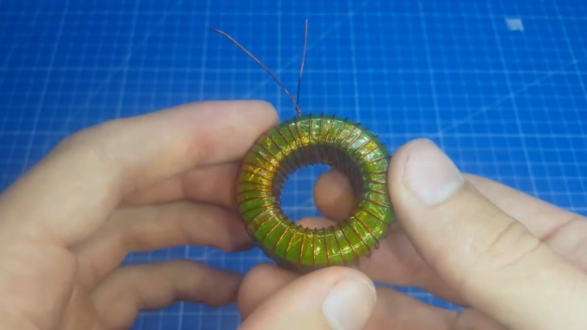
Everything is very clear here. If you need to wind in several layers, then you can immediately winding two cores, and repeat the same operation with a loop. After winding the secondary we isolate it and the transformer is completed on this. You can still go through the nylon threads along the entire length and strengthen the windings, but this is at your discretion.
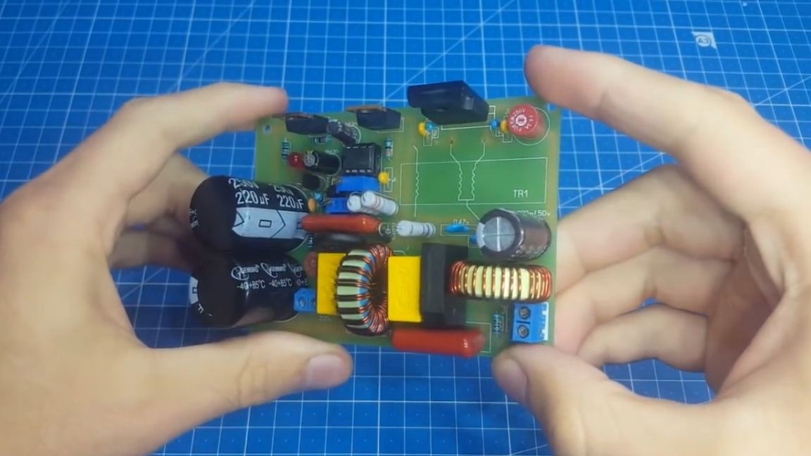
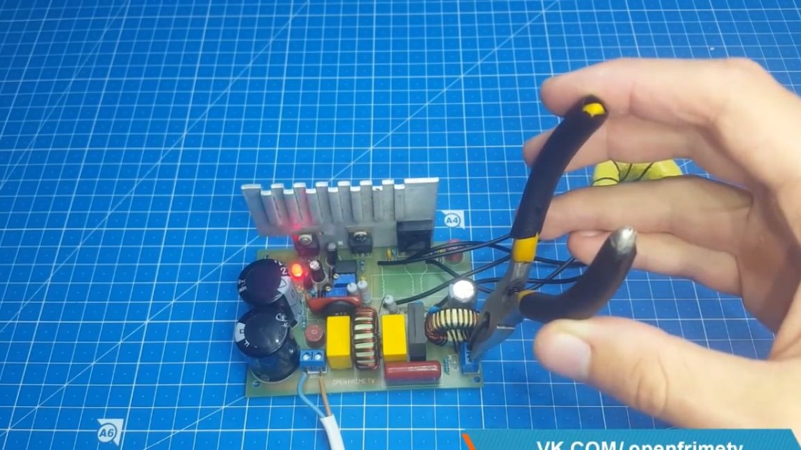
Now you can test our homemade transformer. For this we’ll use such a board.
We soldered the transformer to the board, and we measure the output voltage.
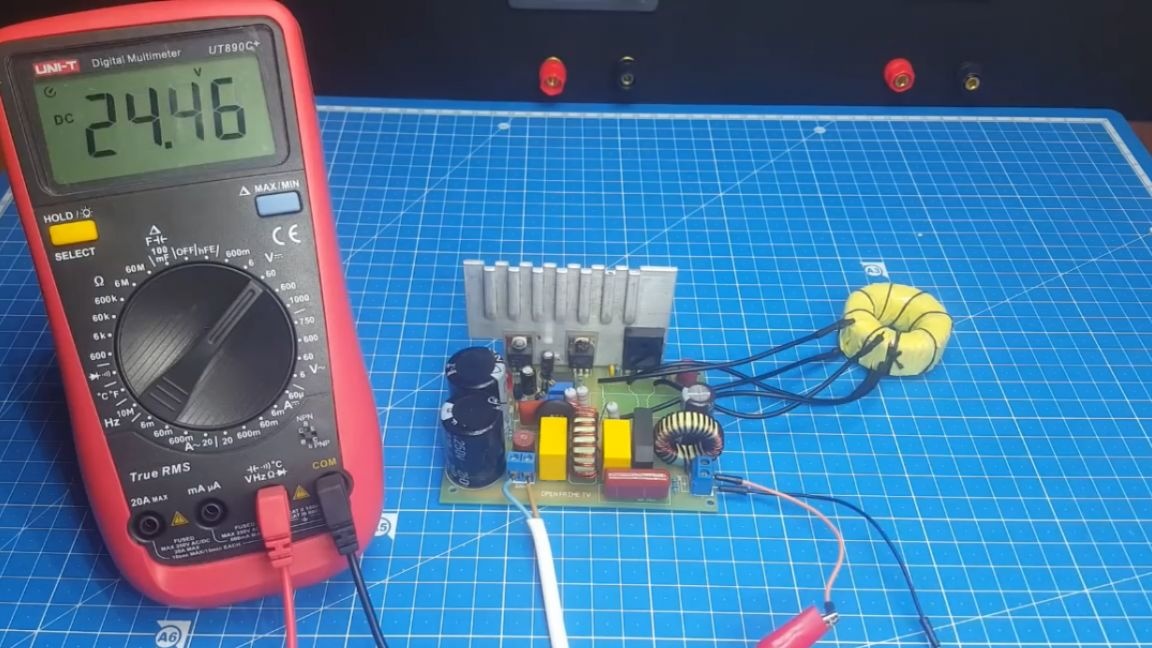
As we see, it coincides with the calculated one. Now you can connect our electronic load and see how the transformer holds power.
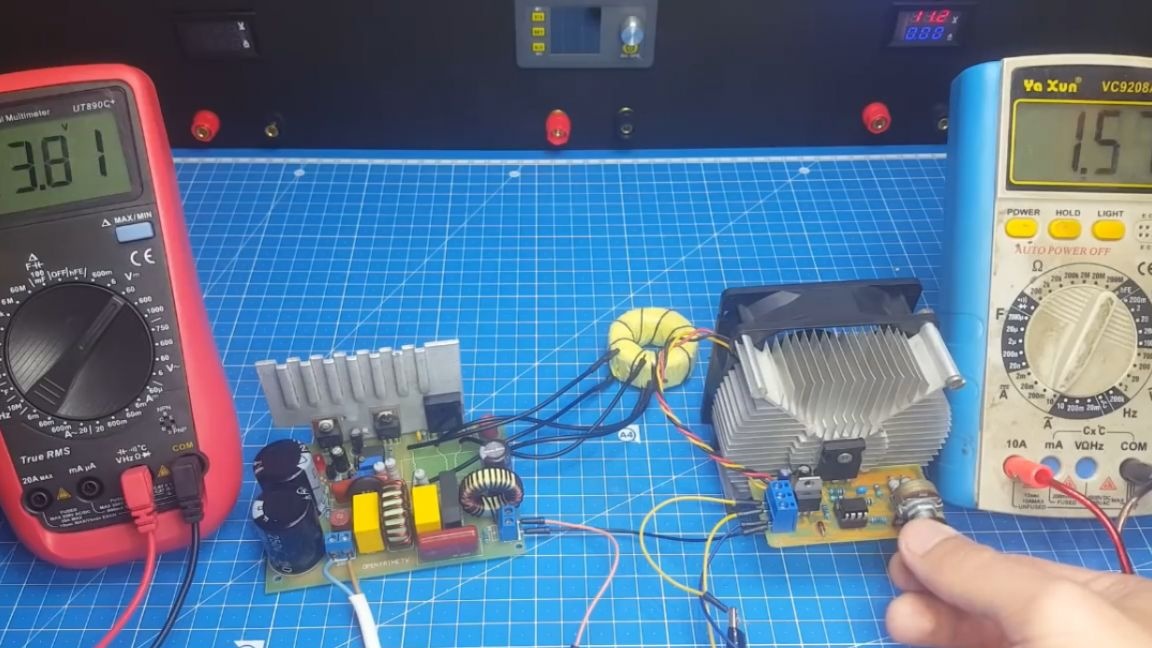
As you can see, with an increase in power, there is a voltage drop, though insignificant. Well, finally, we check the protection against short circuit.
As you can see everything is fine, the block is coping.
Well, that’s all. Thank you for attention. See you soon!
Video: