
Today, together with the author of YouTube channel "Radio-Lab" we will assemble a radio designer.
This is an LED sound level indicator. It is intended for visual control of the sound signal level, which facilitates the control of the device, for example, so that the signal at the input or output of the sound amplifier or microphone amplifier does not exceed a certain level. This is very convenient to do using a signal strength indicator. It also visually looks beautiful. Such indicators can often be seen on factory devices.

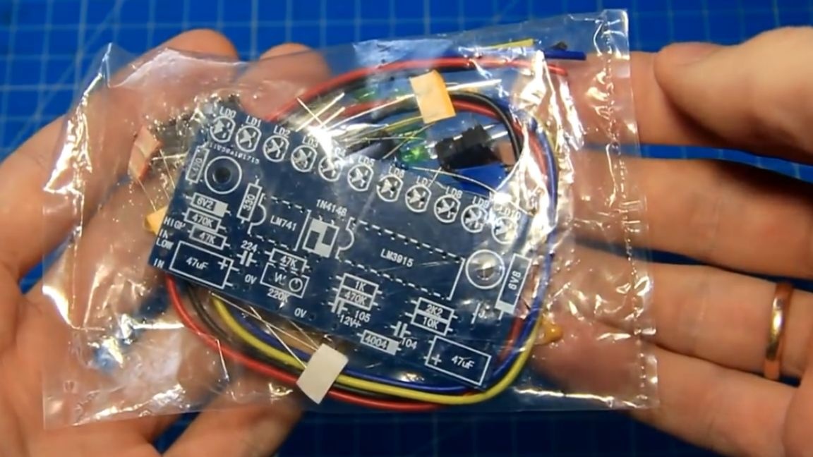
Most often, these are jumping luminous columns or moving arrows. Direction indicators are expensive, because for now we will collect a cheaper LED version. The kit comes in a sealed bag, carefully cut and get the contents of the package.
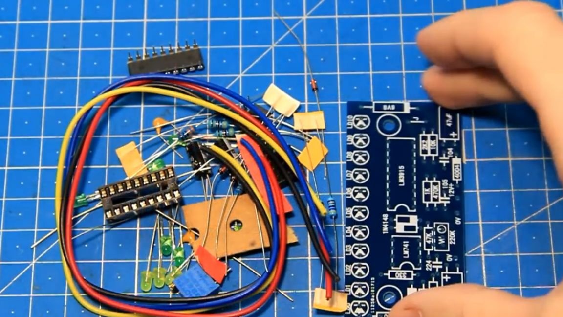
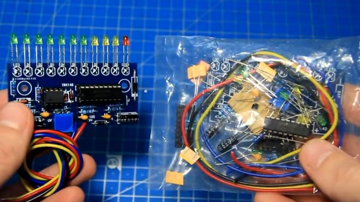
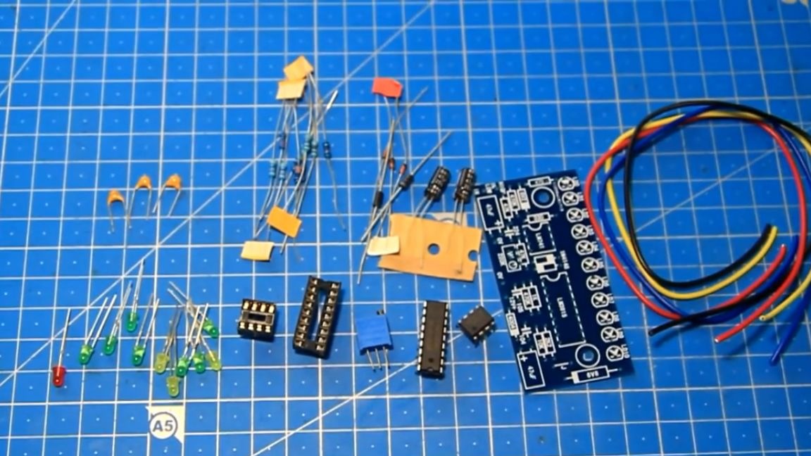
The set includes a printed circuit board, wires and various radio components. For convenience, we decompose all the details, there are not many of them.
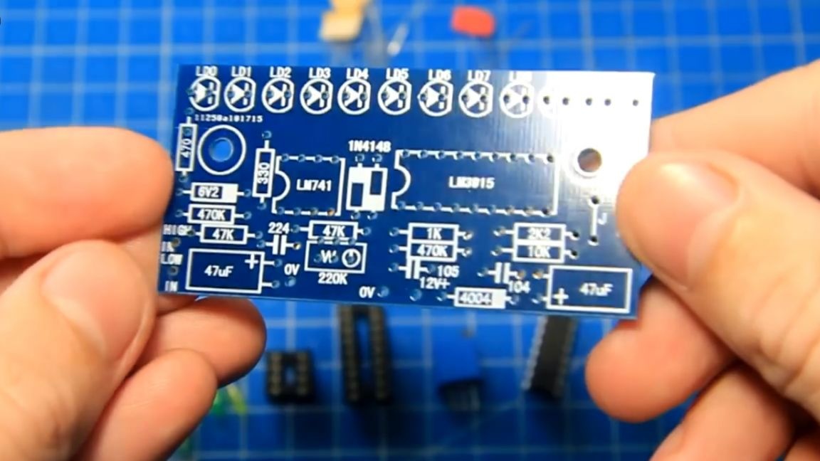
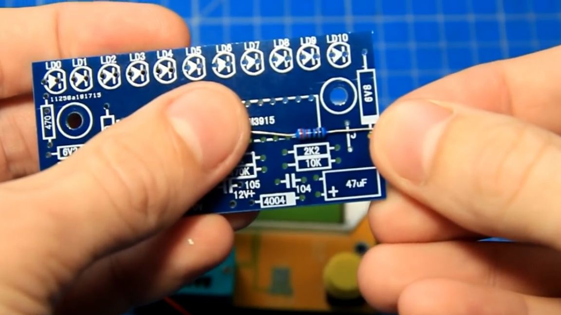
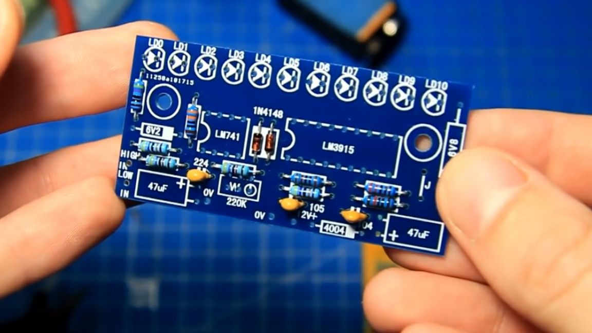
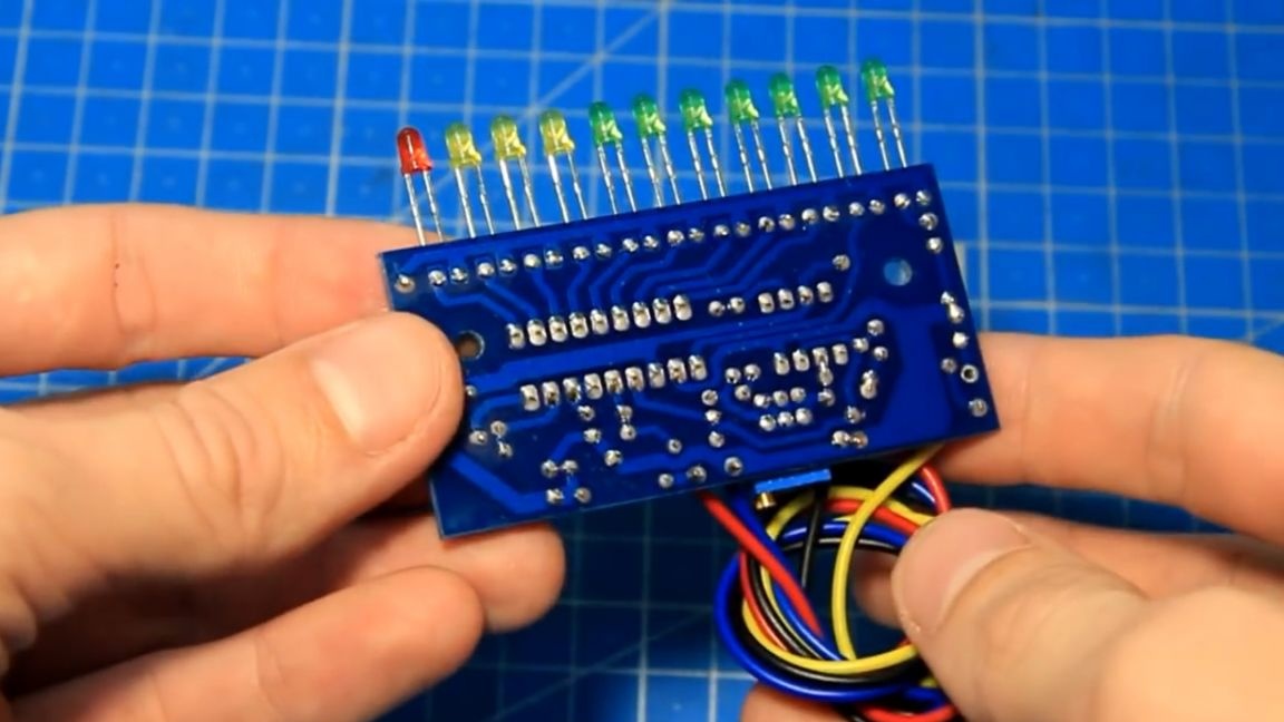
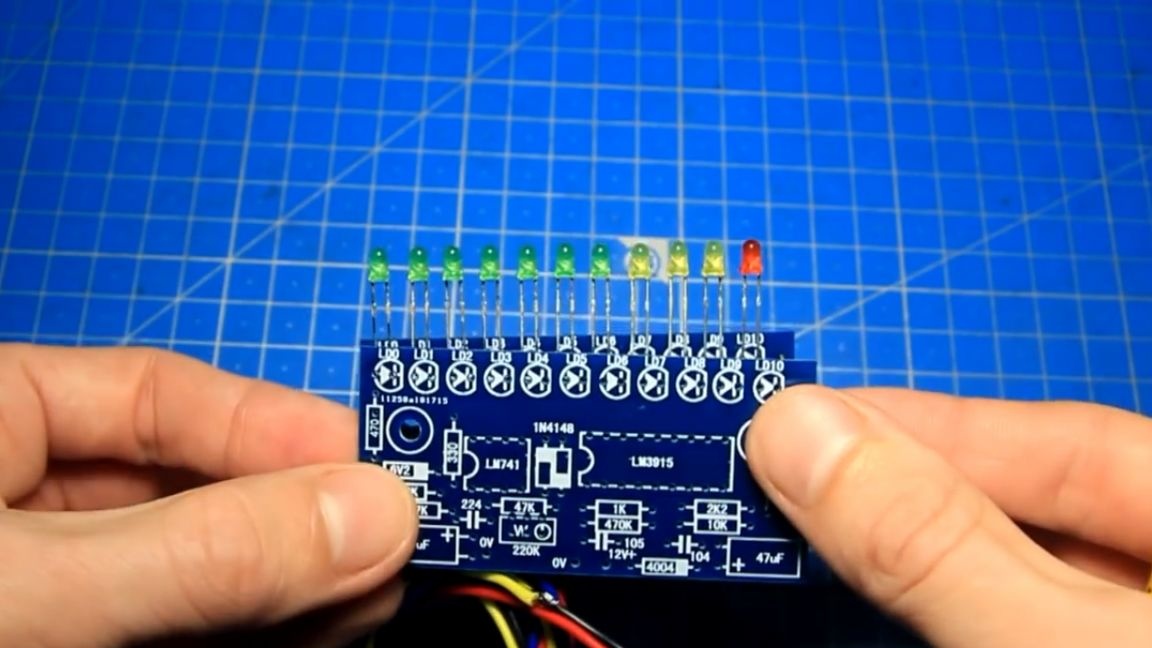
No instructions included. It looks like a printed circuit board of excellent quality, what and where to solder is on the board itself.
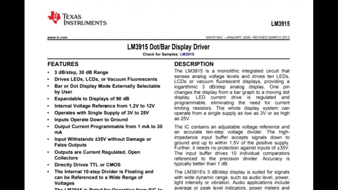
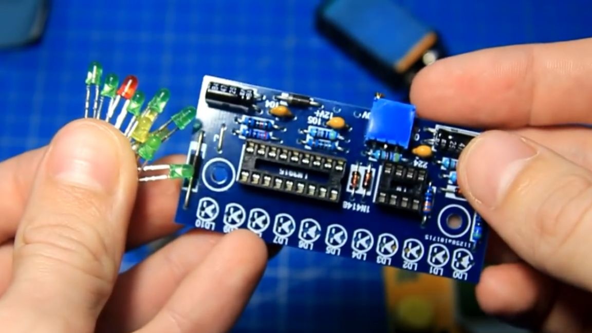
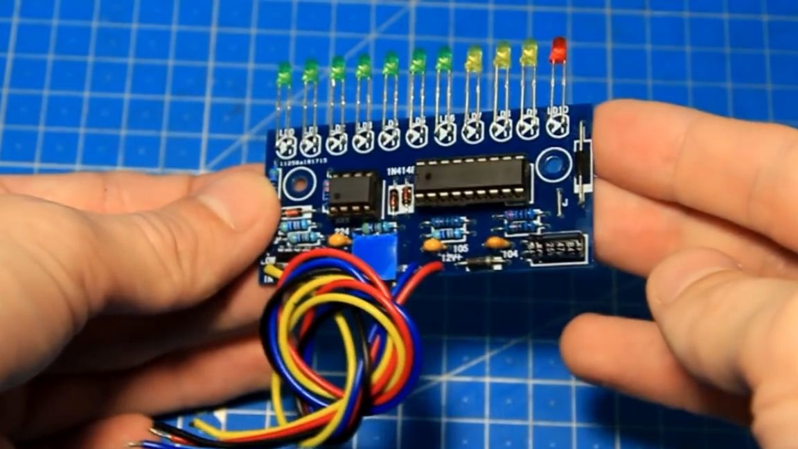
The basis of this module are 2 chips.
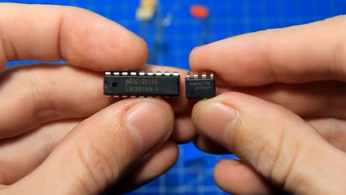
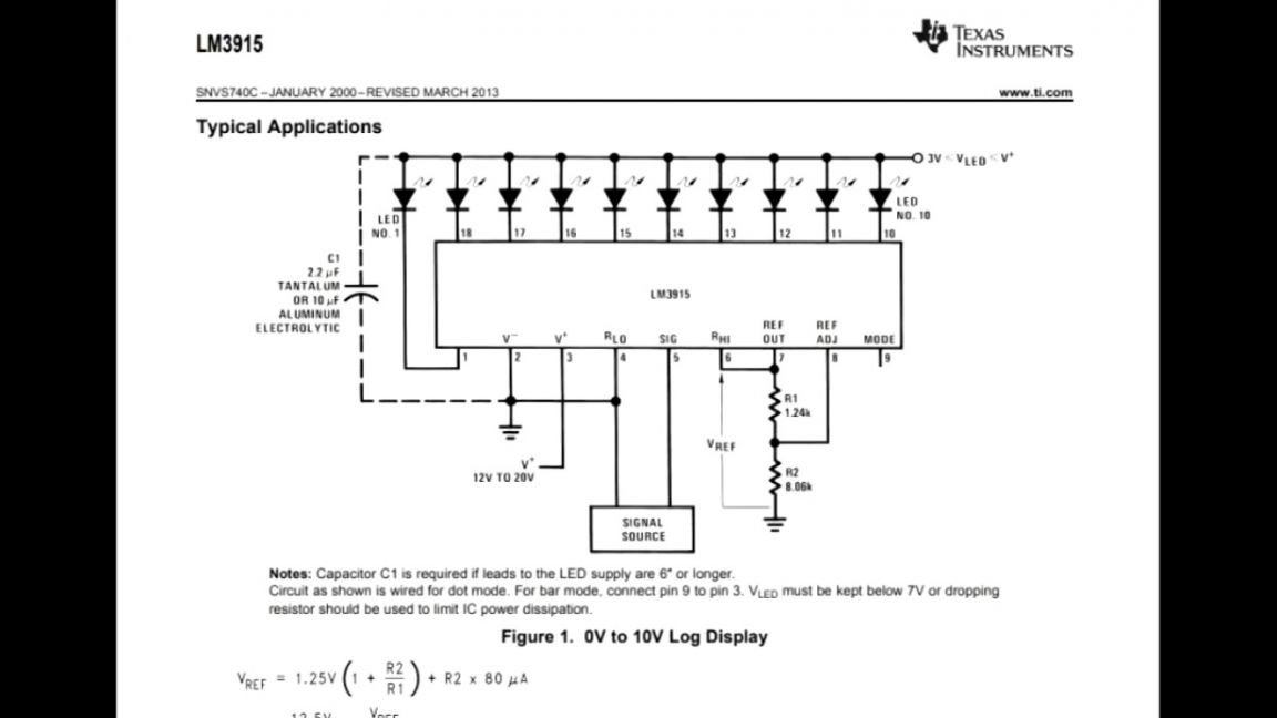
One is the UA741 operational amplifier and the LM3915 driver chip with a logarithmic scale of 10 outputs, a 30 dB range of 3 dB per step. This is a popular chip, information on it is on the Internet.
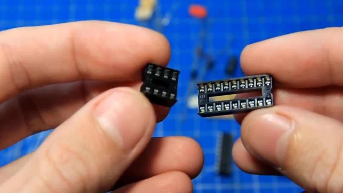
The chip set contains sockets, convenient in case of replacement or tests.
Well, now you can start assembling. First of all, we will install constant resistors. To find out the denomination of a detail, the author uses such a tester of radio components.
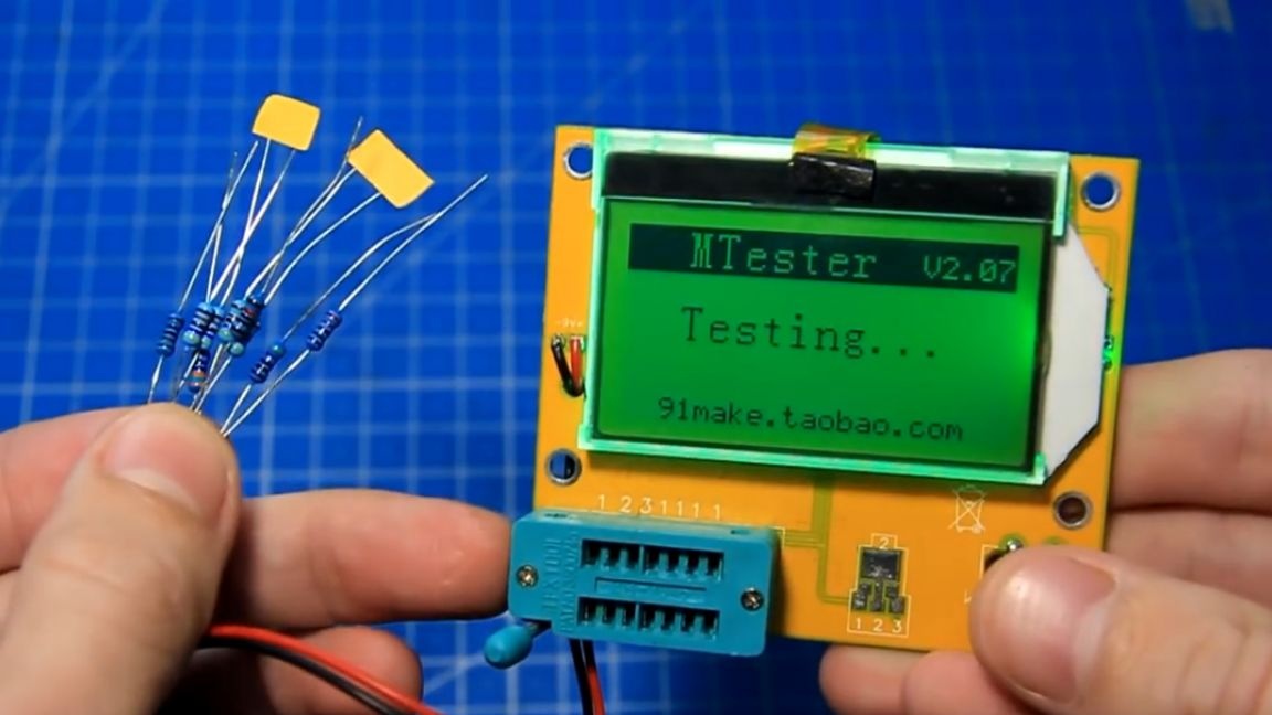
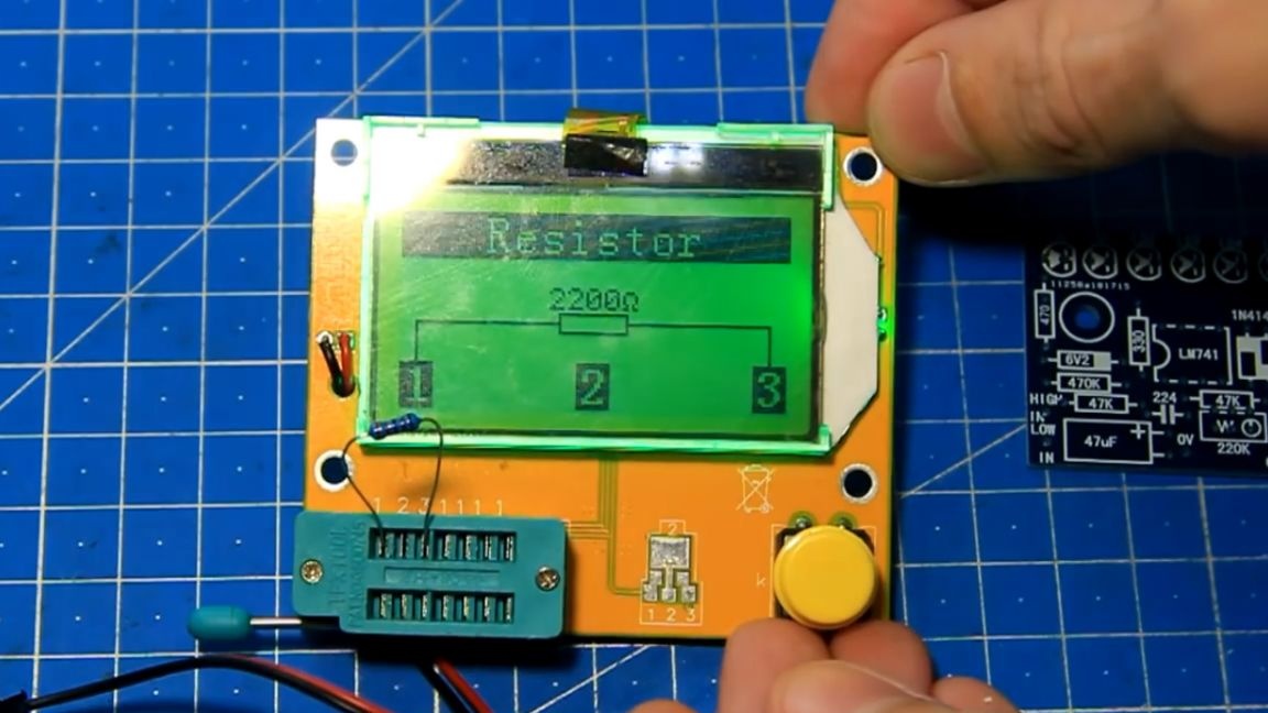
It's comfortable. The resistor was 2.2 kΩ. And now, by marking, we find the place of its installation on the board.
We try on a resistor, bend the legs, install, bite off the excess and solder the parts to the board.
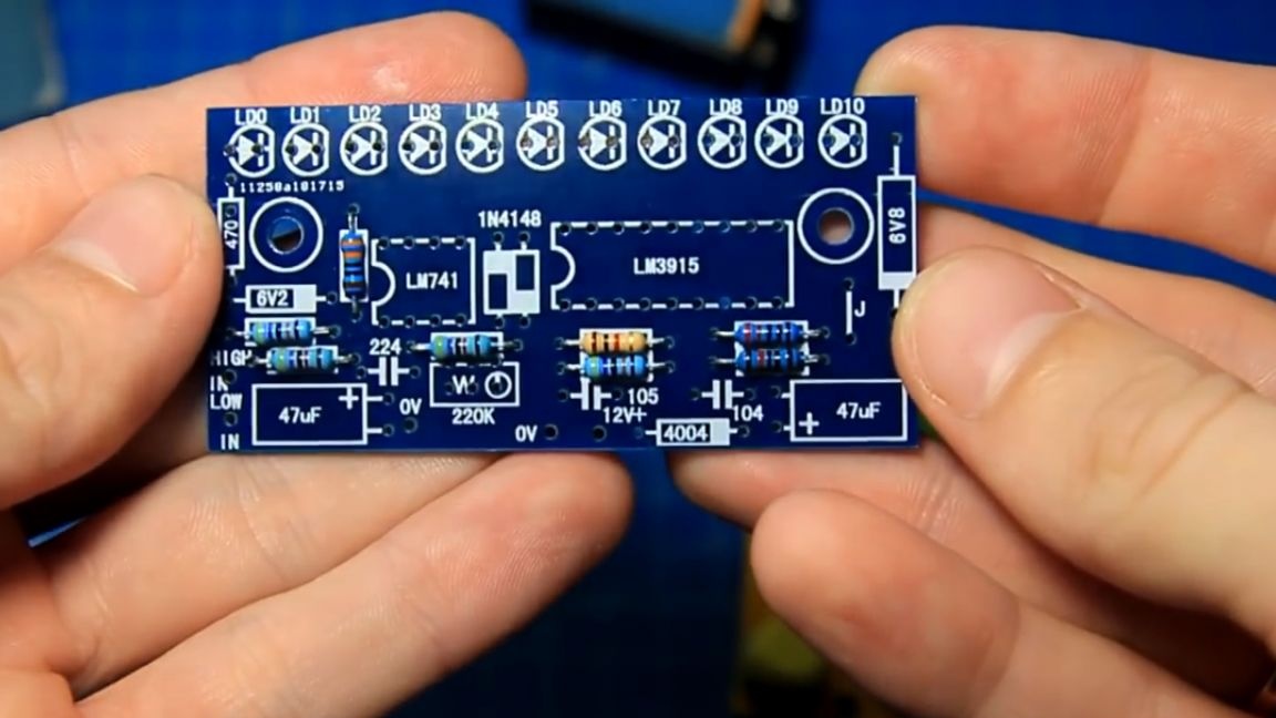
The set includes 3 multilayer capacitors, the ratings are indicated on the case. We look at the board and install them in their places.
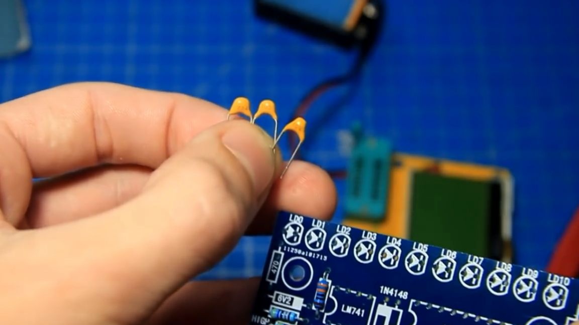
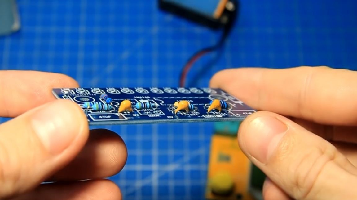
Yellow capacitors installed. Now we will solder diodes and zener diodes. They are the same and easy to confuse, you need to carefully look at the markings on the body of the part.
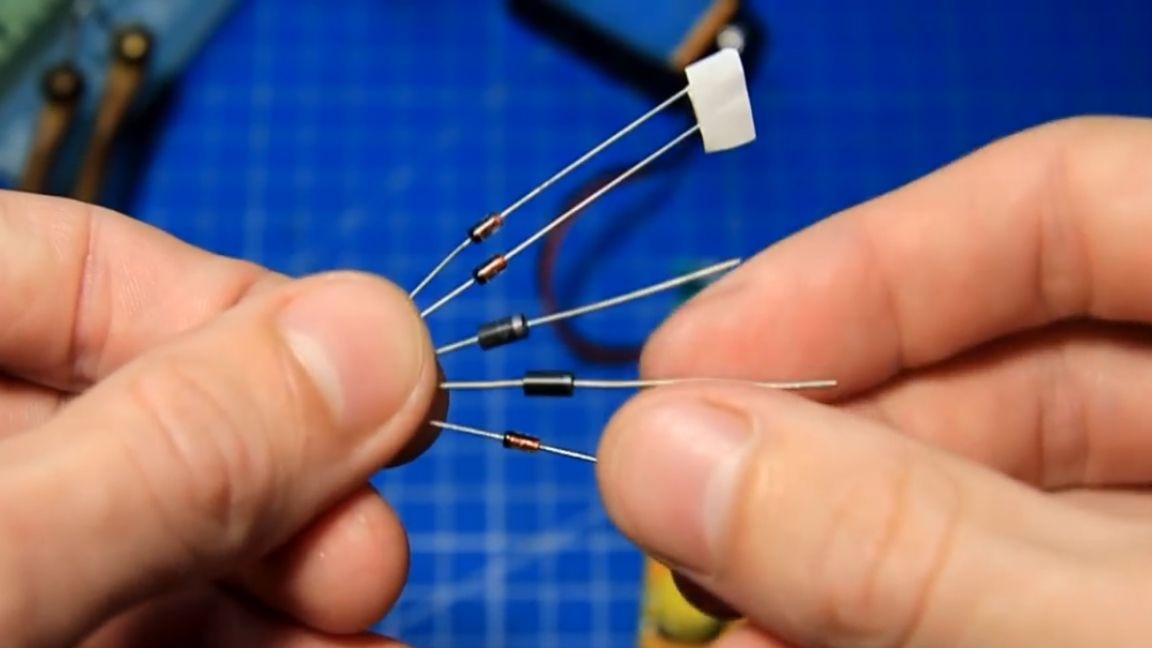
We look at the marking and take 2 diodes. We find their place on the board. Be sure to observe the polarity, for this there are marks on the case and the board.
Here again, the same diode and zener diode.
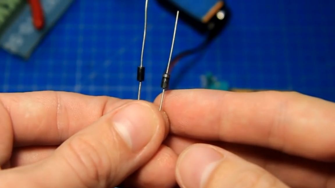
Again, there is a marking on the case and you need to look for similar numbers on the board.Here on the case of this part there is an inscription 6.2V - this is a zener diode. We look on the board and put it in its place.
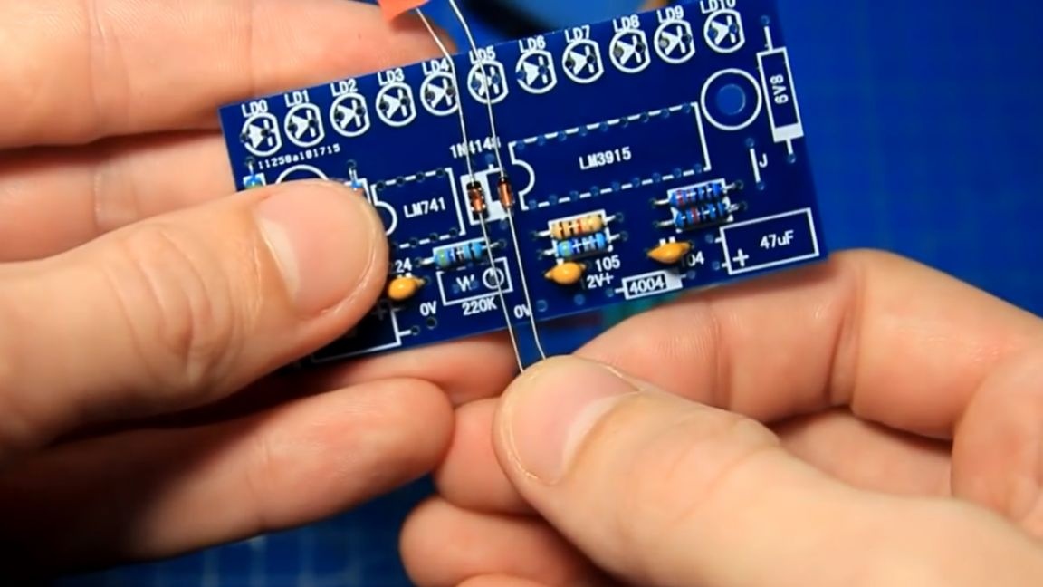
It remains to install and solder the zener diode, which is larger. Diodes and zener diodes are installed. On the board there is a jumper "J", bend a piece of wire and install this jumper.

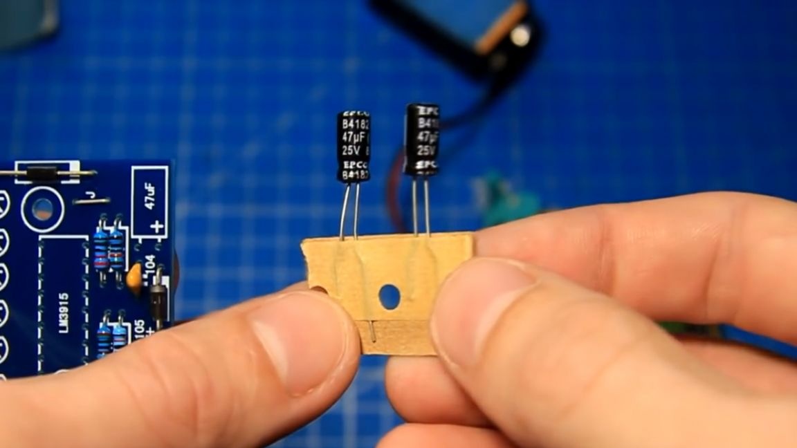
The electrolytic capacitors are the same, you just need to observe the polarity of the installation (for this there are marks on the case of the part and on the board).
In the figure, we set the tuning resistor. For the keys we install the socket panels for the microcircuits. It is possible to install a trimming resistor horizontally - and we will do so, more compactly.
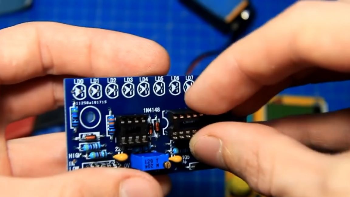
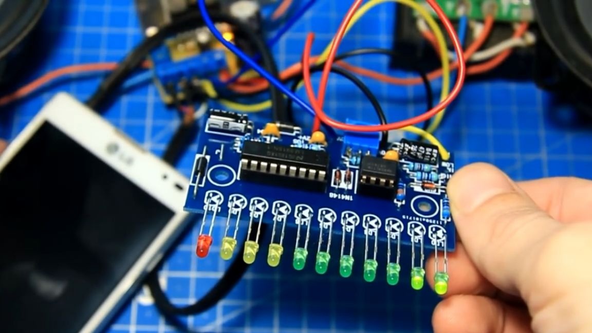
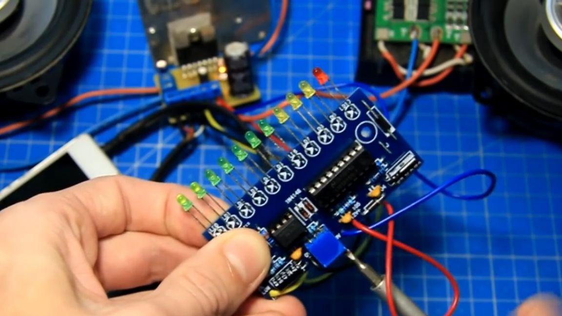
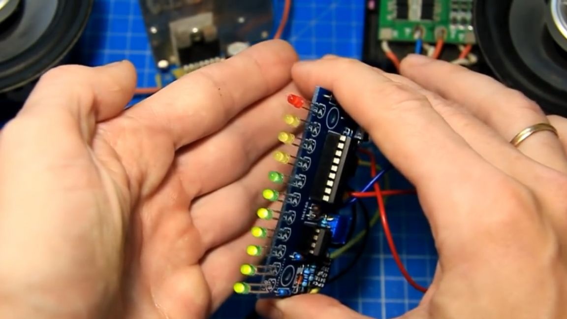
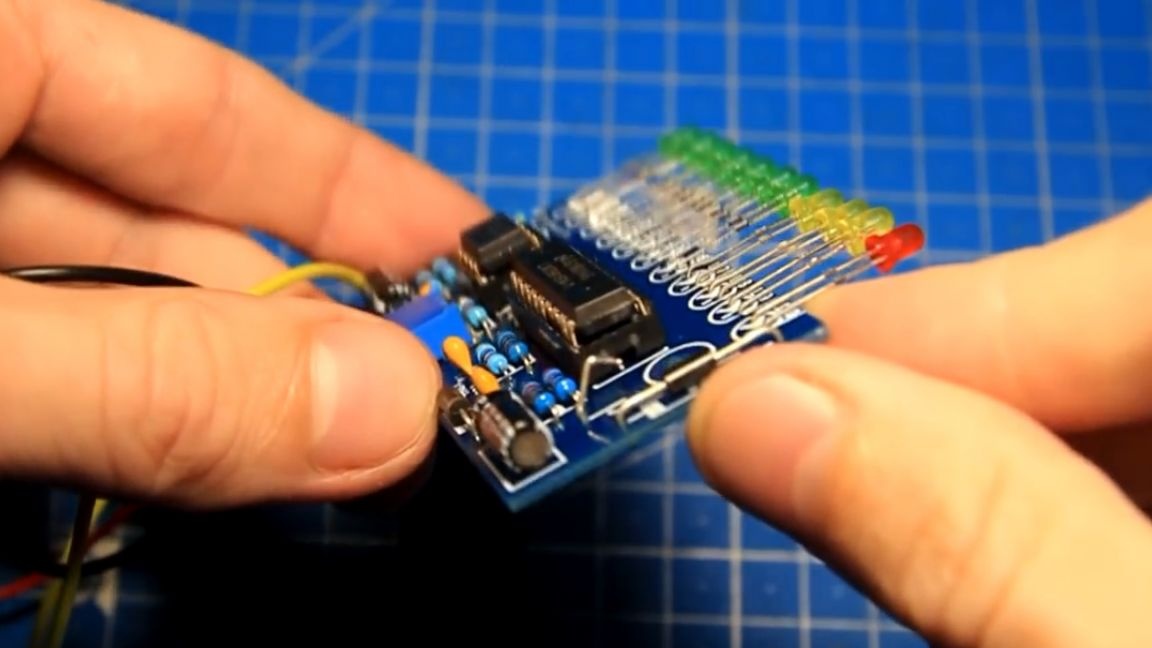
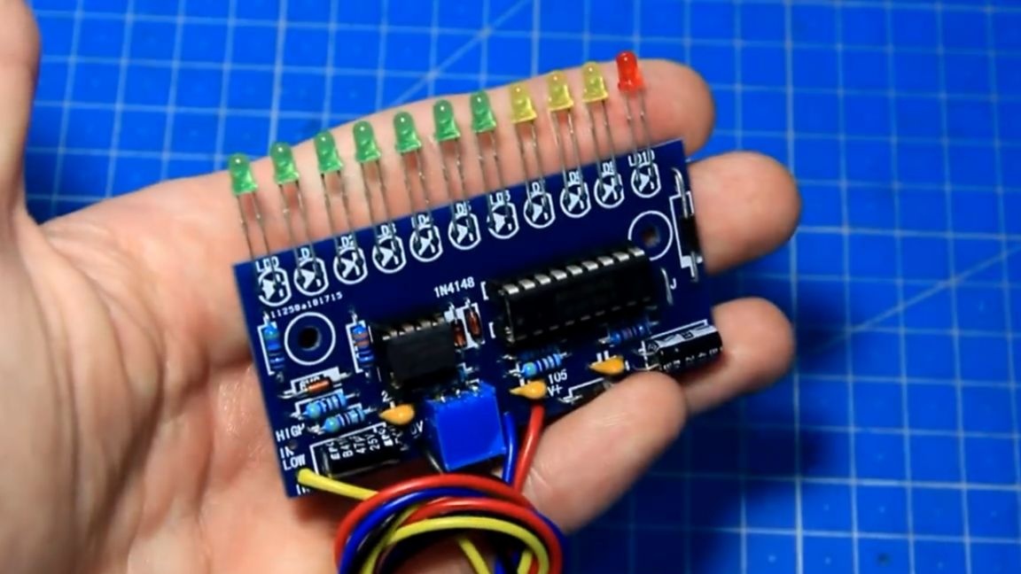
On the board there is a place for installing 11 LEDs. A longer leg of the LED is a plus. According to the drawing or marking, we install the LED on the board. The tenth LED is red.
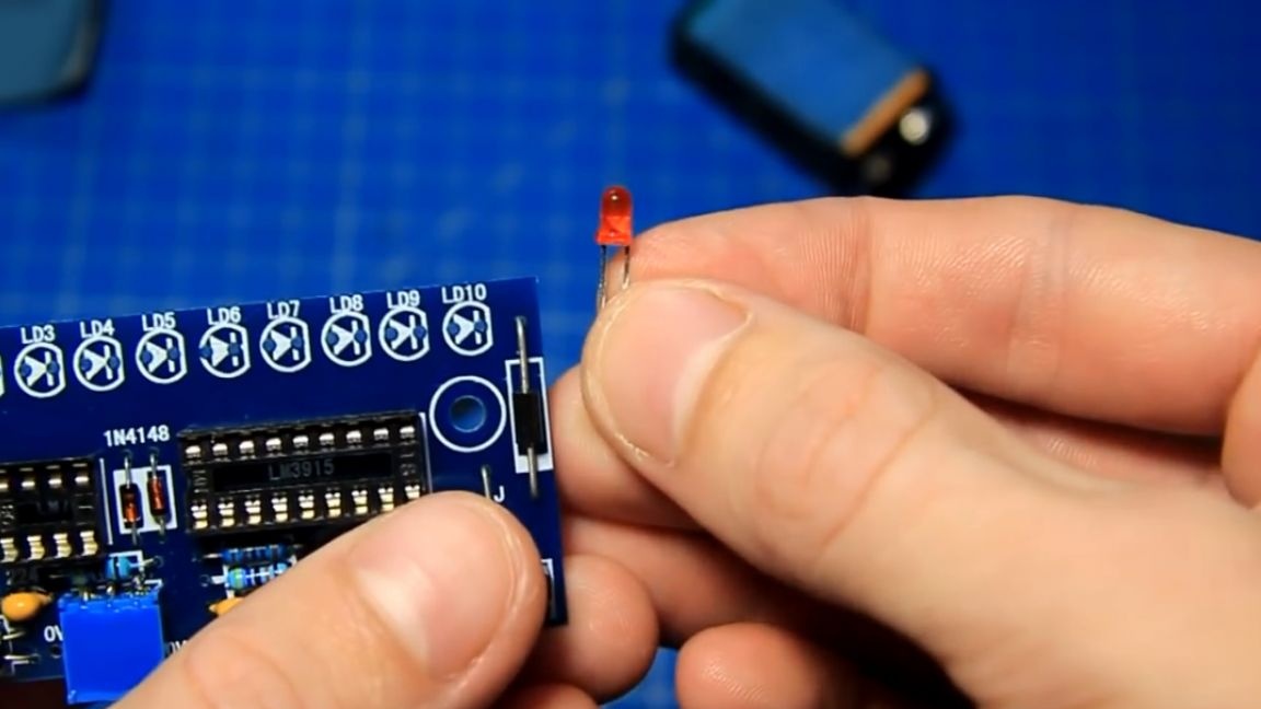
Further, with a decrease in the number, yellow and green LEDs are used. We solder all the LEDs into place.
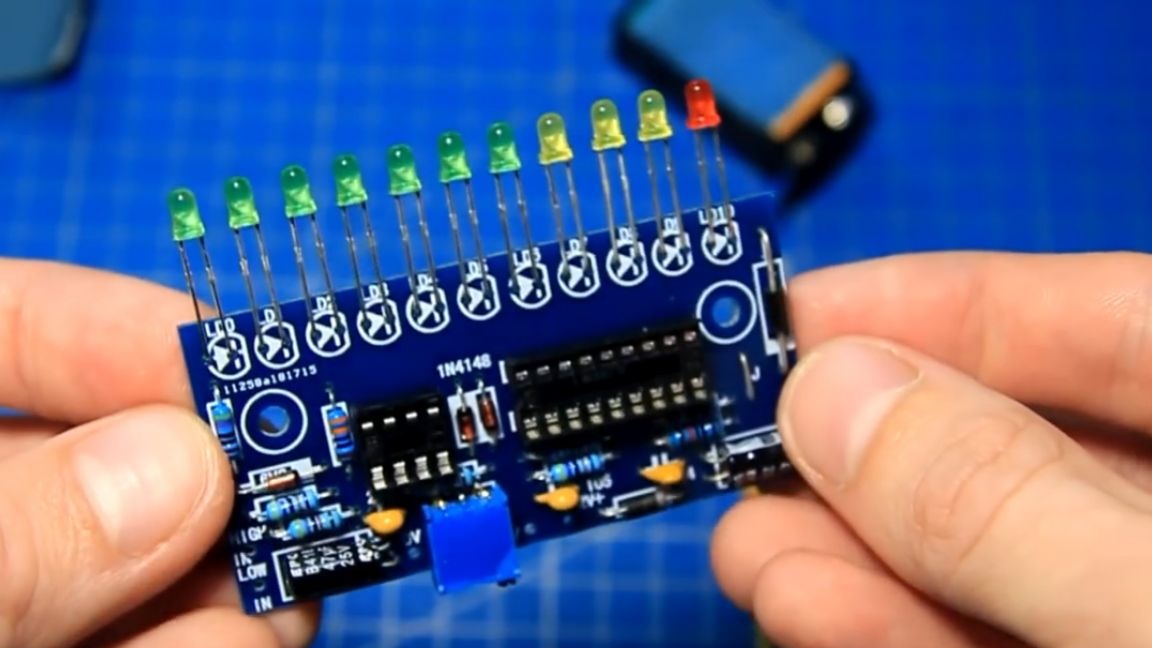
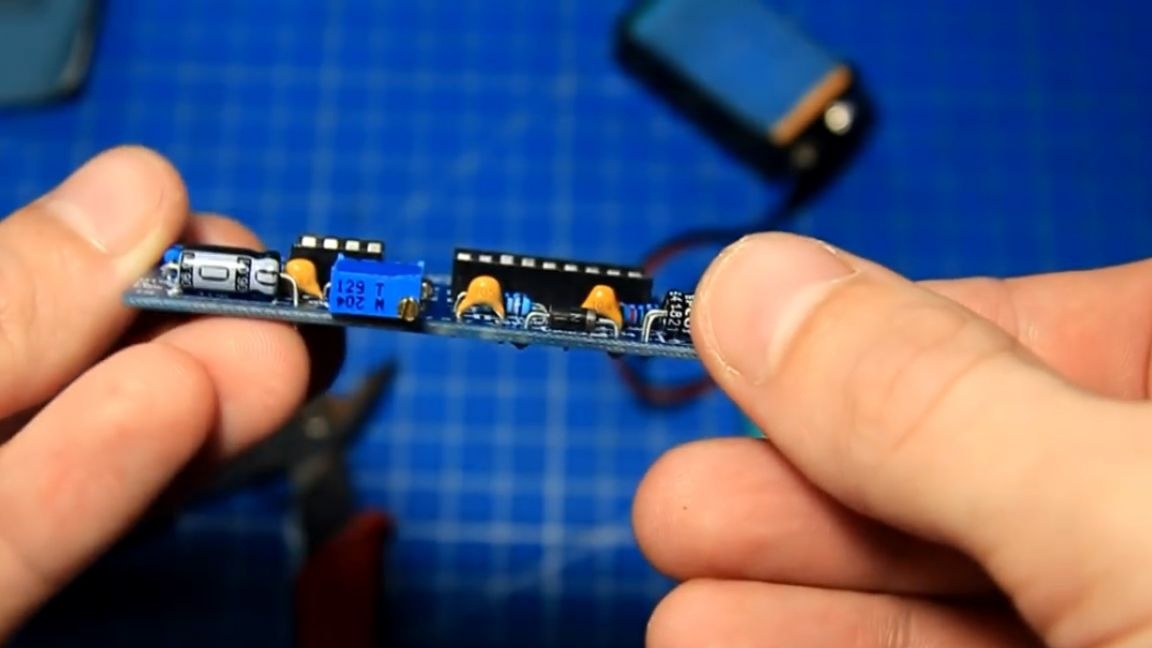
In height, everything is exactly. Next, we install the microcircuit keys in their places in the panel.
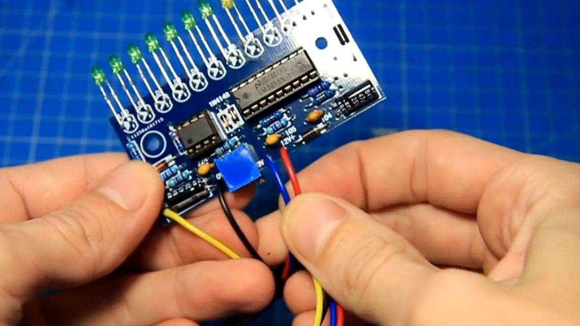
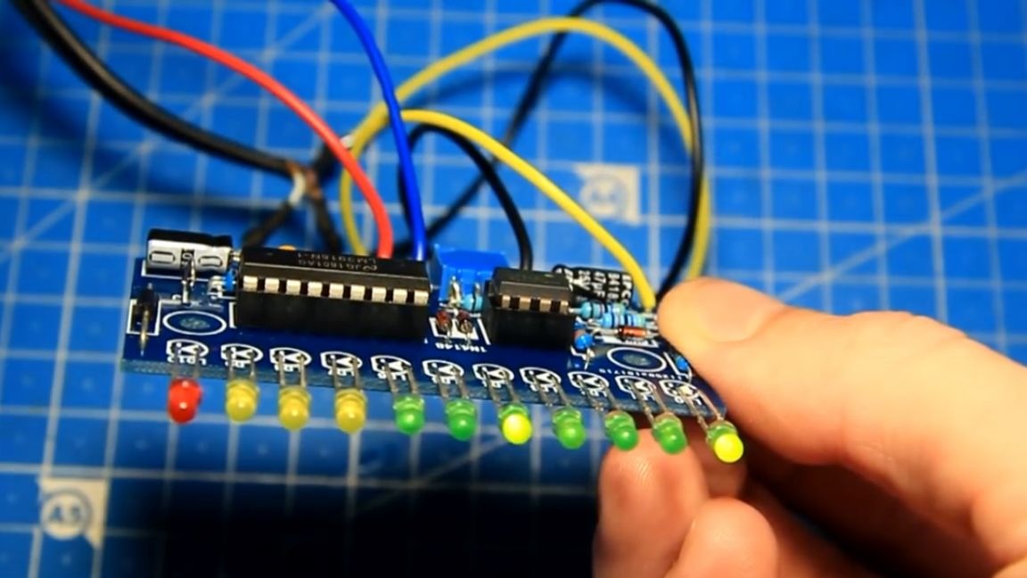
The author also dubbed wires for connecting the indicator (red and blue - plus and minus power, and yellow and black - this is the input for the signal).
Well, now, you can say, everything is ready. The signal strength indicator is fully assembled, the flux washed and now everything is beautiful.
This board has 2 inputs: low level (if the signal is weak, for example, at the amplifier input) and high level, for example, if the board is connected to the amplifier output. We will use a low-level input.

In the picture you can see all the characteristics of the inputs.

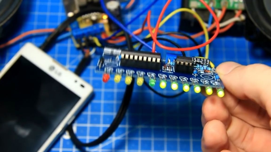
Board voltage is 12V. To test the performance, we will power the board from a 12V battery. If you apply power, you can see that the LED column bounces and fades - this is already good.
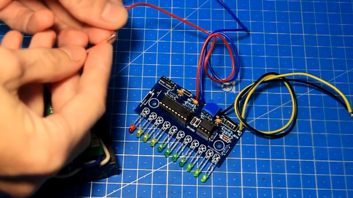
The zero LED lights up continuously when there is power. To give a sound signal, we will use this wire to connect to the phone:
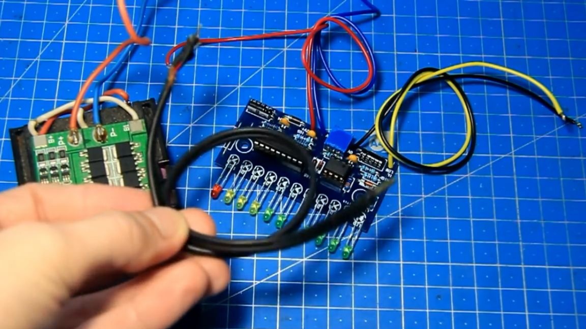
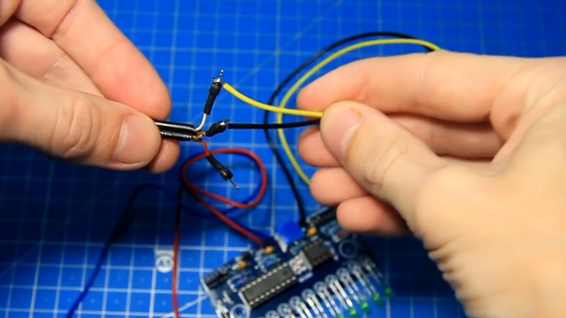
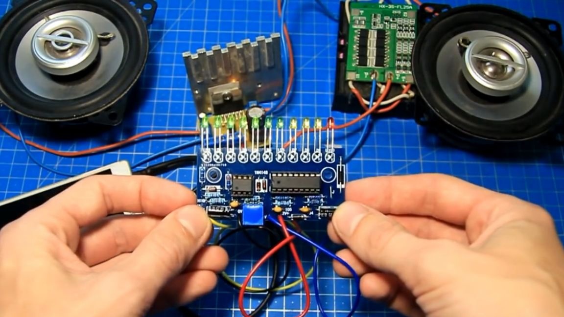
The author soldered the yellow wire to the signal sound wire, and the black one to the common wire. If there are two boards, then the second one is similarly connected to the second channel. To test the just-assembled LED indicator of the sound signal level, the author decided to use an amplifier on the TDA70377 chip with 12V power for convenience, to show, but you can take another one.
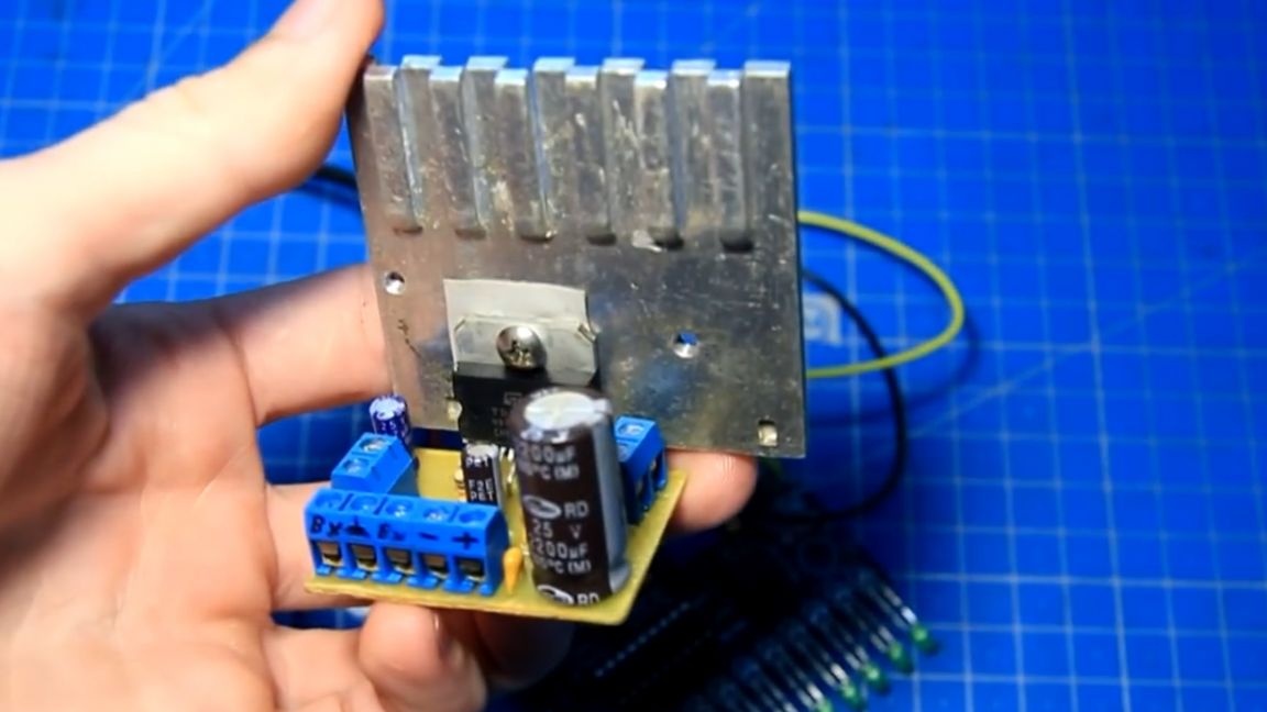
We connect the line input wire to the amplifier input, and a signal level indicator is connected to one of the channels there. The indicator power wires are connected in parallel to the amplifier power wires.
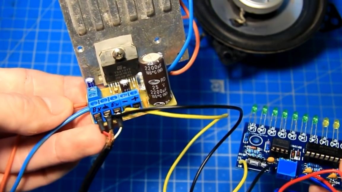
Check if everything is fine, then apply power to the amplifier. You can see that the level indicator is working (the indicator LED indicates this).

A sound amplifier is also powered. Now try to connect the phone and turn on the music. Let's look at the operation of the signal strength indicator.
Now let's try to add the volume to maximum.
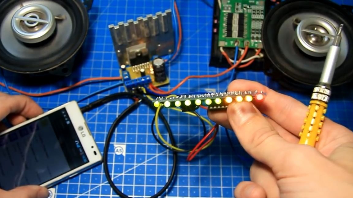
There is also a sensitivity setting on this board. By turning the tuning resistor counterclockwise, more LEDs light up.
This allows you to configure the board as needed. This adjustment makes it more versatile. If the jumper “J” is removed, then the board switches from the “column” mode to the “point” mode, also sometimes a necessary function.
But if you need columns, then the jumper must be soldered into place. Mounting the boards is easy, for this there are specially provided mounting holes.
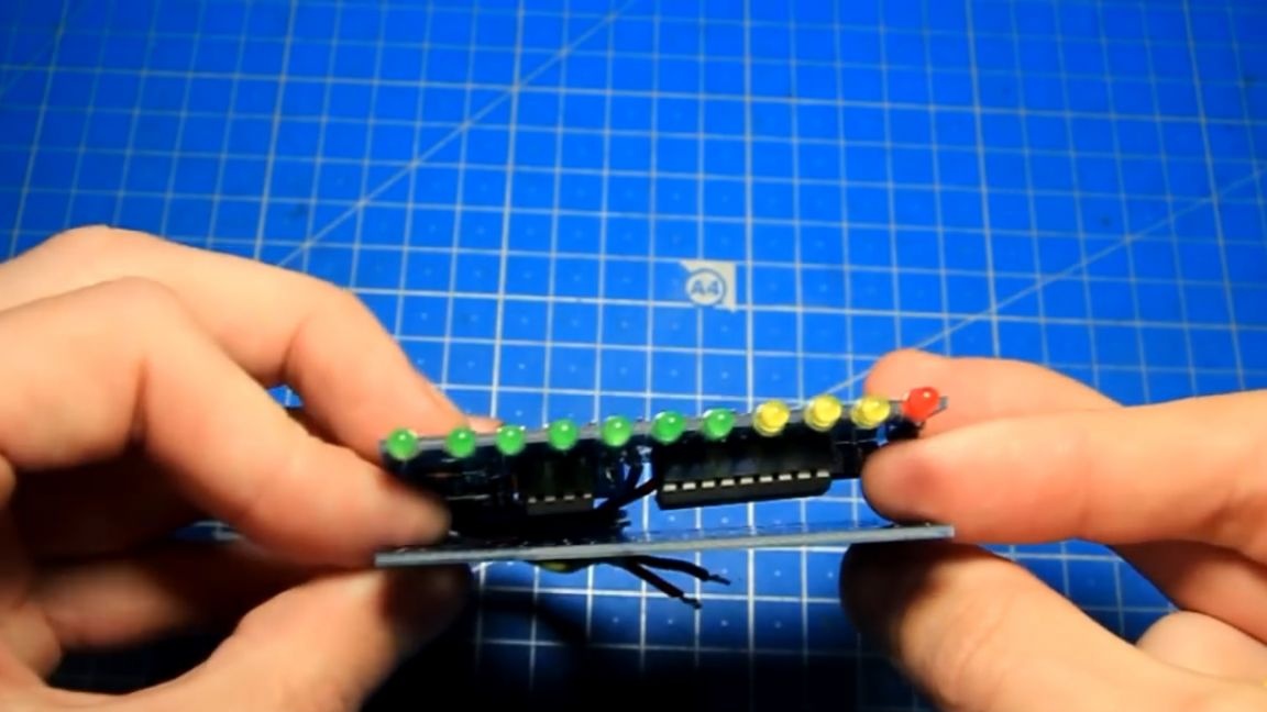
Also, the boards can be mounted on racks one above the other according to the principle of a sandwich and get, for example, a stereo indicator from two boards, or a quad indicator and so on.
Here is such an interesting radio designer. LEDs can be changed to more interesting, larger or rectangular. The author did not have problems with the assembly. If everything is correct, then the indicator will work immediately.It is connected and configured quite easily, you can try to collect. Using this board, you can make beautiful visualizations, for example, for an amplifier, a portable speaker, and much more, and also control the level of the input and output signal. In general, it’s already a matter of fantasy. Well, that’s all. Thank you for attention. See you soon!
Video: