
Now, together with the author of the YouTube channel “Open Frime TV”, we will assemble a fairly simple and reliable laboratory power supply with operational amplifiers.

I think everyone who wanted to assemble a linear laboratory power supply on operational amplifiers often came across this common scheme:
The Chinese even began to mass-produce it.

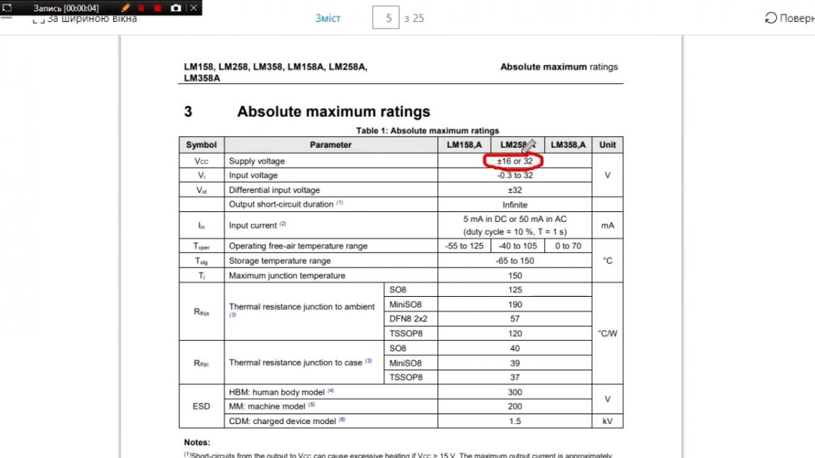
As you can see here, operational amplifiers were used to stabilize the output voltage, but there is one thing - but which makes this circuit very unattractive. This is because the input voltage cannot exceed 30V. Most people are confused by this limitation, because transformers are usually 24V and 36V. Finding a 30V transformer is problematic, and redoing a transformer for a power supply is irrational.
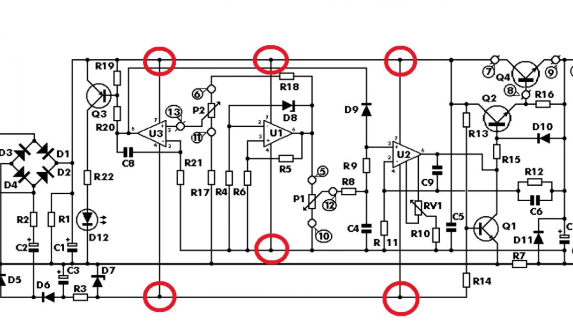
Why is this so? And all because operational amplifiers in this circuit are connected directly to the supply voltage, and they have an upper limit on the input voltage.

Of course, this option may suit someone, but he did not like the author, and then the search for a good scheme began. The desired circuit was found on one of the forums.

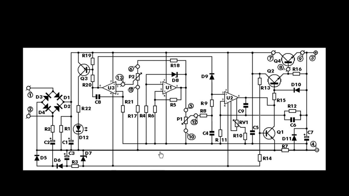
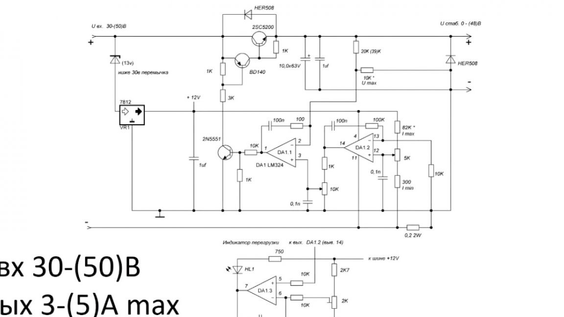
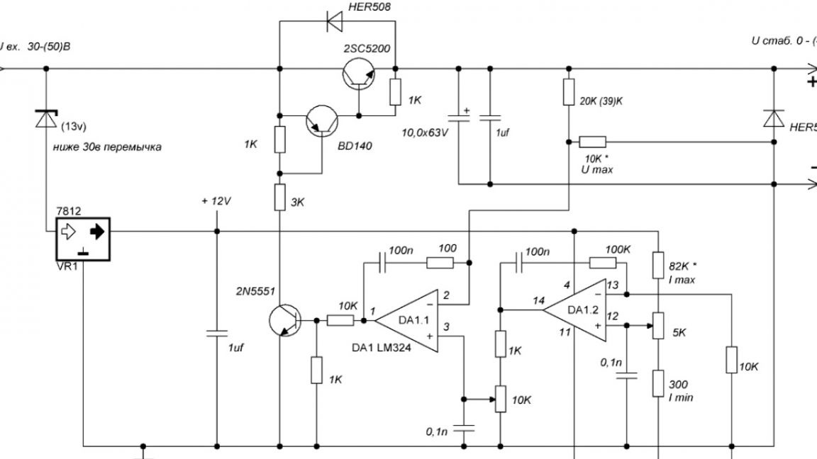
Several options were proposed there, the author tried one and the other, and eventually settled on this scheme:
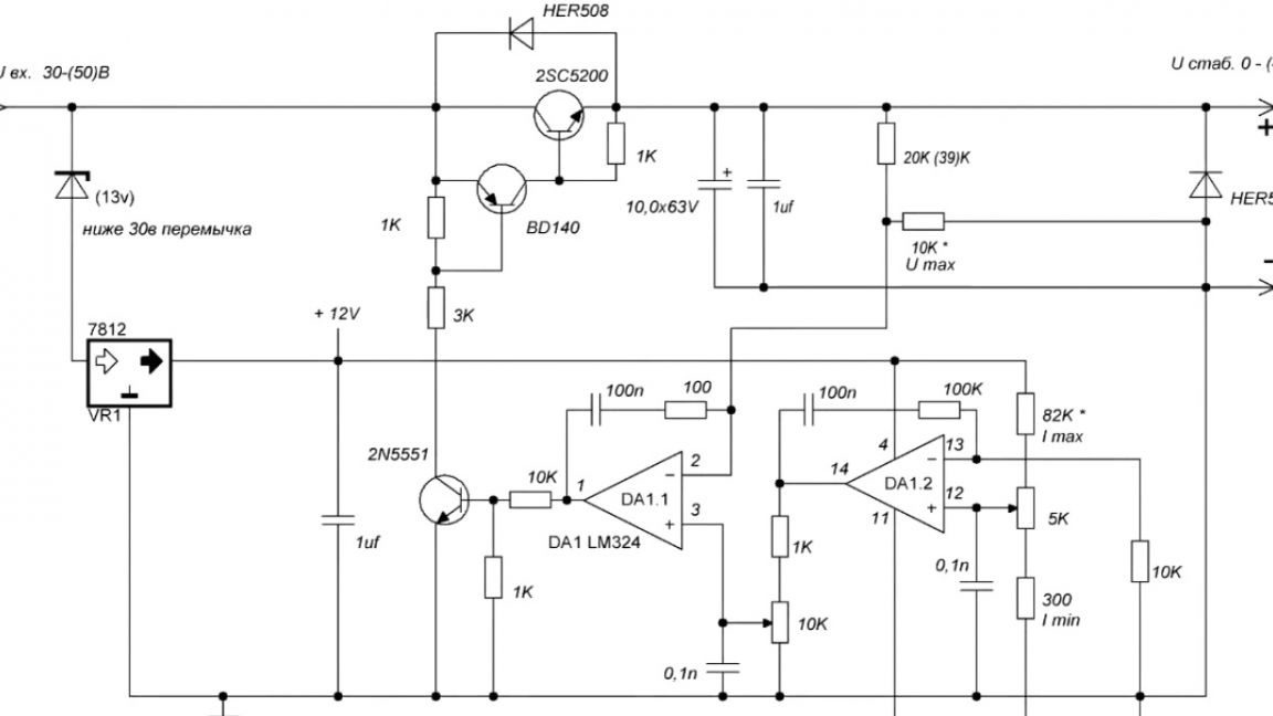
Specifications: an impressive input voltage (can reach 50V), the output current can be 5A (but this value is variable, more details during tests).
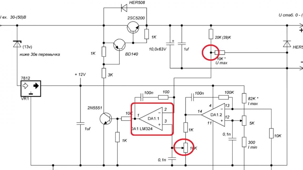
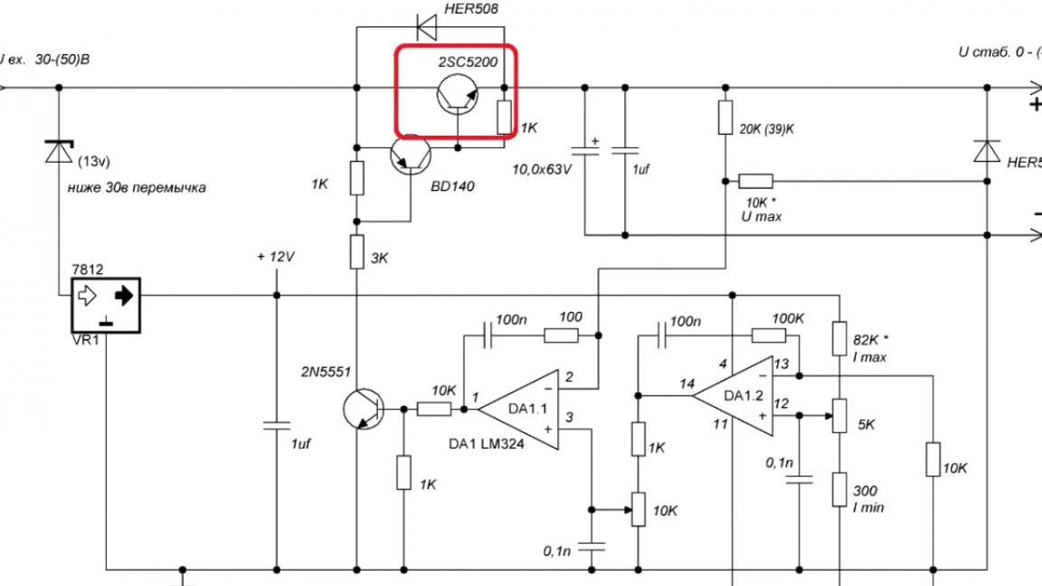
Now a few words about the operation of the circuit. One operational amplifier compares a given reference voltage and output, and depending on this, opens or closes the power transistor.
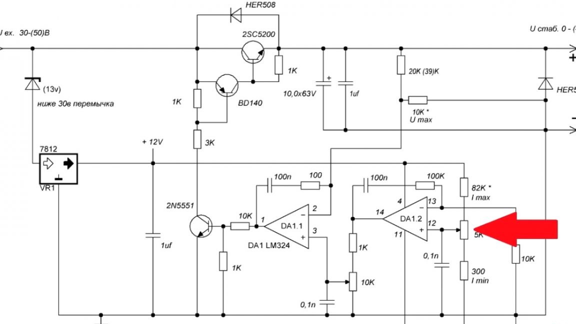
The second operational amplifier, monitors the voltage drop on the shunt.
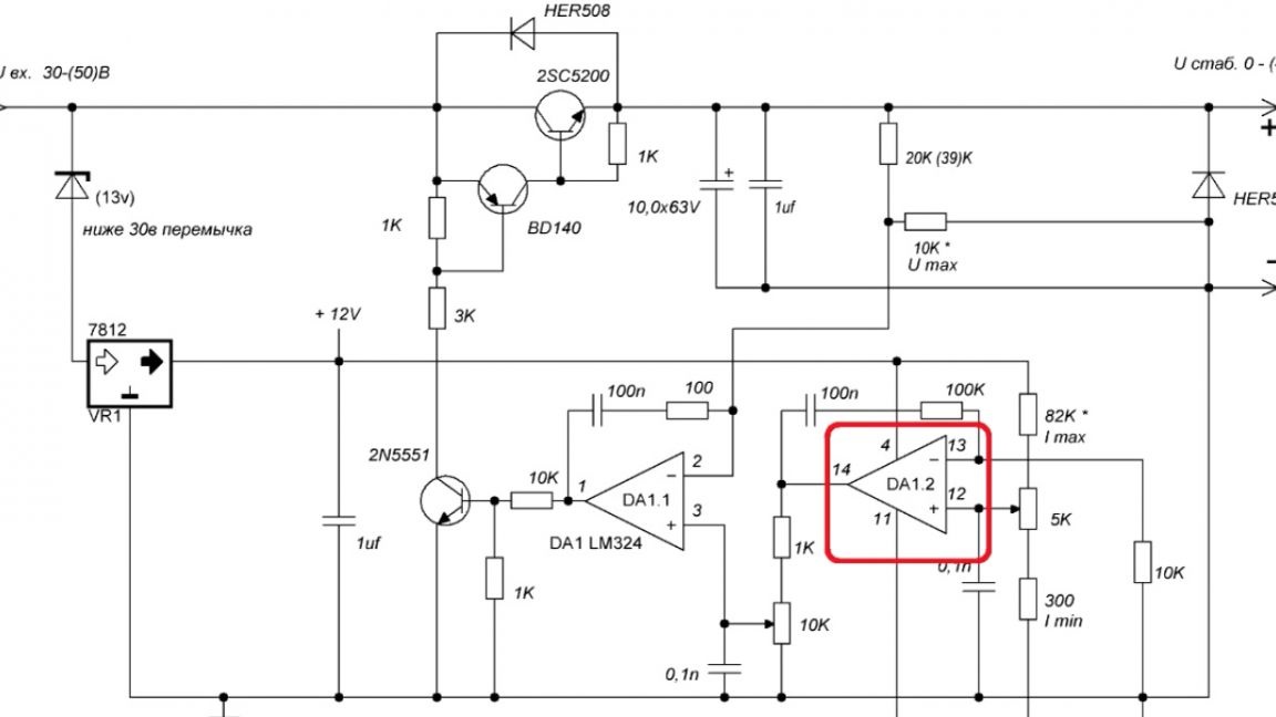
The meaning of his work is the same as the first, as soon as the voltage drop on the shunt becomes higher than a certain level, he will reset the voltage for the first operational amplifier. This one will start to close the transistor until the drop voltage on the shunt is equal to the set current value.
Also on the forum, people shared their options for printed circuit boards.

But in size they were quite large, and then the author decided to sketch just such a printed circuit board.
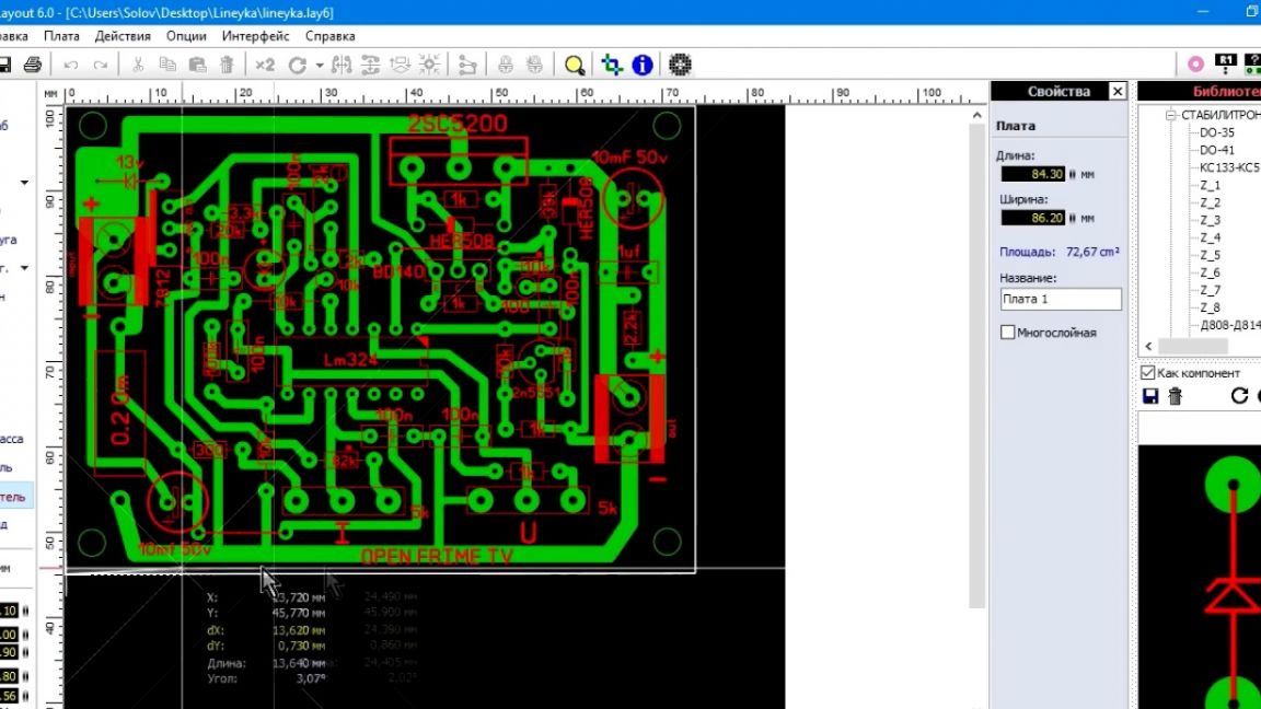
In terms of size, it turned out to be very compact. First, he made a test case using the LUT method and checked everything.


I liked the scheme in the work.After that, the author decided to beautifully design it and sent it to the manufacture of a Chinese company.

And so the boards were delivered. The author eagerly opens the box. They are well packed. Let's get a handkerchief and take a closer look.


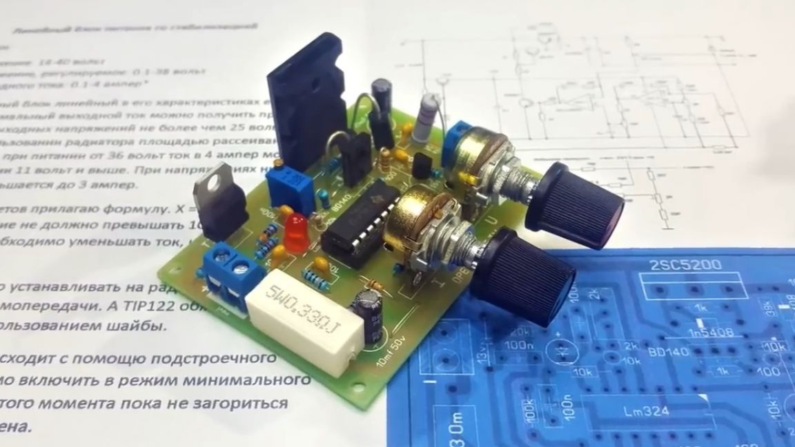
Well, quality is always on top. I immediately wanted to collect this board and check in work. The number of parts pulls to the average level. Soldering takes about 20 minutes of strength.
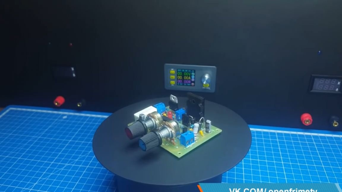
As a result, we get such a beautiful board:

You can test it. For this we need a power source, we also need electronic load.
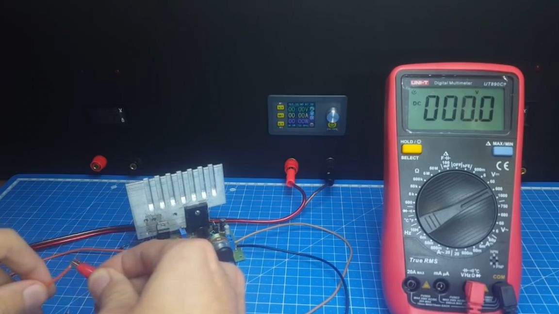

First of all, check the minimum and maximum output voltage.
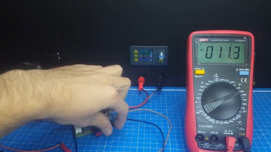
As you can see, the minimum threshold is 0V, and the maximum is only a couple of volts less than the input. Now you can check how much the output voltage sags under load. To do this, do not remove the probes from the voltage measurement and hang a light bulb there for a voltage of 36V rated at 100W.
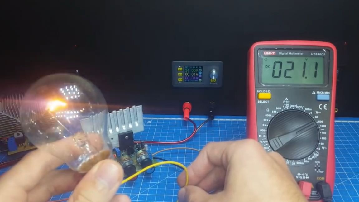

As we see, stabilization is on the level. Now let's check what current the circuit can produce. But to begin with, there is a caveat: the maximum current that can be obtained from this circuit varies. Now in more detail: the output current at 40 volts is limited to 5 amperes, but that's not all, when setting the maximum current, you need to make sure that the power dissipated by the transistor does not exceed 100W.

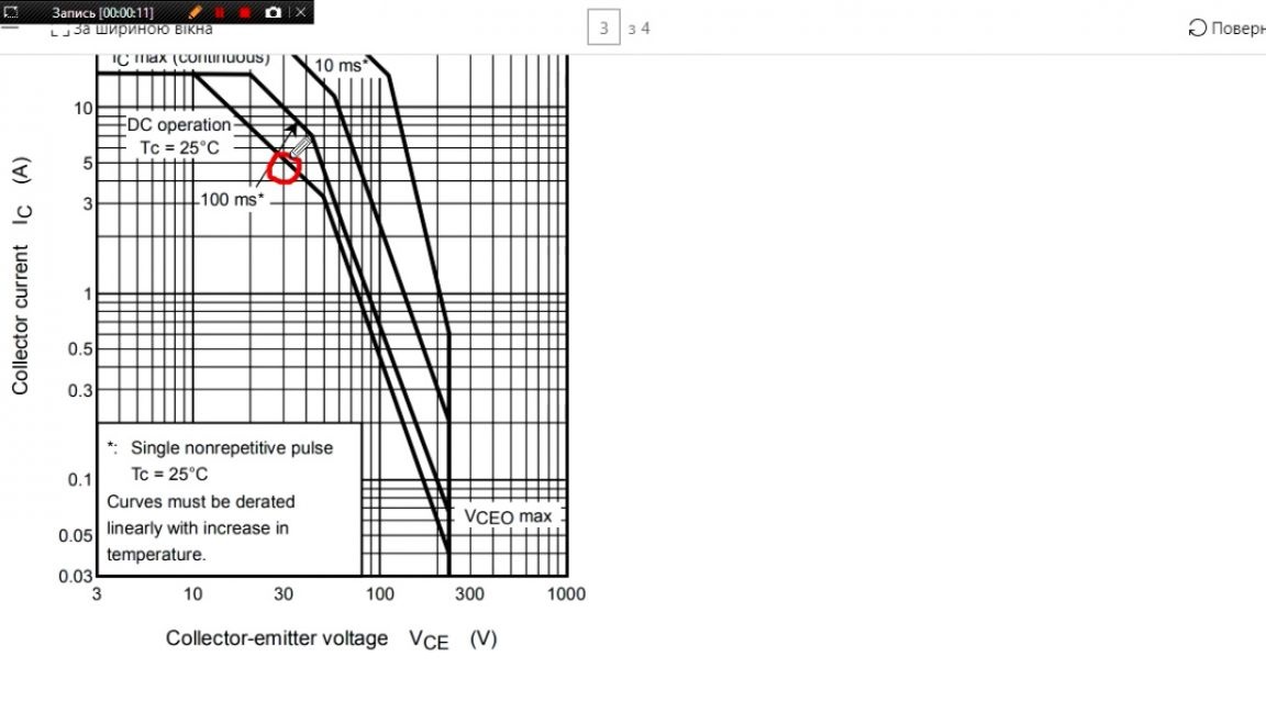

You can calculate this power using this formula:

We substitute the value of the difference between the input and output voltage and multiply by the current consumption. For example, if we have an input voltage of 40V, and a voltage of 2V and a current of 5A are set at the output, then 190W will be dissipated by the transistor. And as you know, he will not withstand such a load.

Therefore, you must either reduce the input voltage or reduce the current consumption. Now you can connect the load. We set the voltage equal to 30V on the power supply. At the output of the linear gauge, the voltage will be 20V. We load with current in 2A. We look at the stabilization of voltage and current.
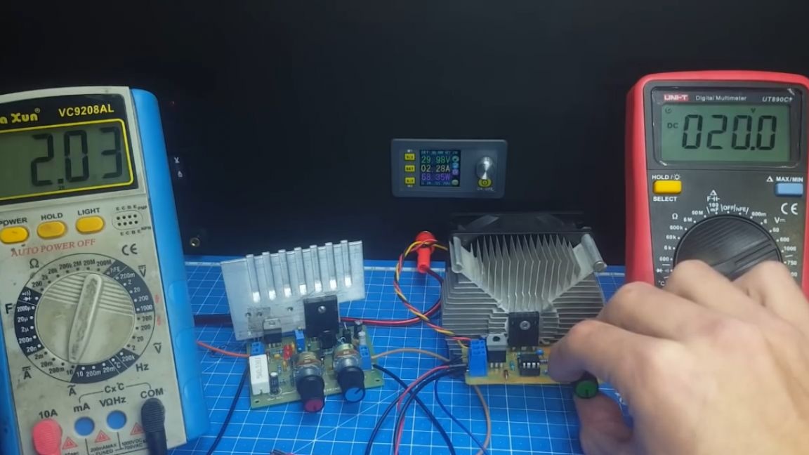
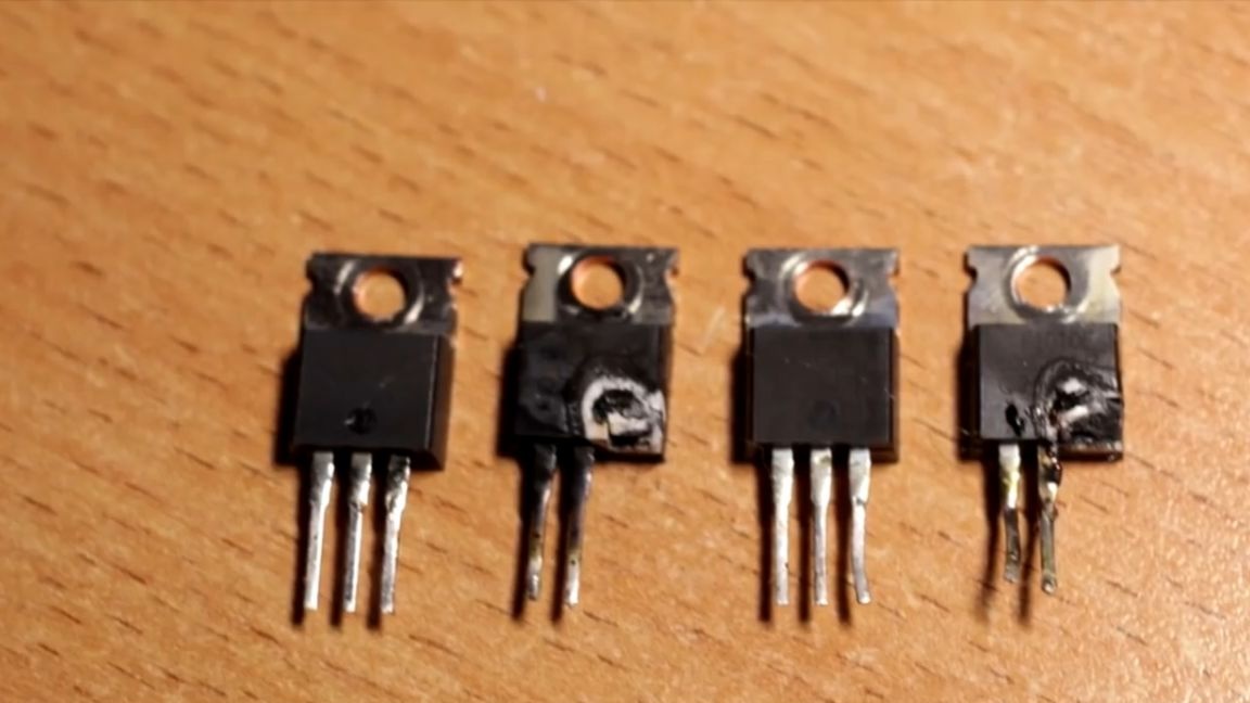
As you can see, the picture is excellent. The block copes with a bang. Also, do not forget to put a rather large radiator on the transistor, since the heating will be very strong, you won’t run away from this, the linear unit does not work differently.


Well, that’s probably all. Thank you for attention. See you soon!
Video: