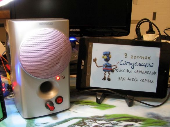
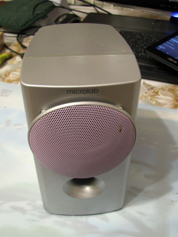
A few days ago, I got a pair of portable speakers "Microlab", faulty and easily so.
And if you, like me, have an itch to collect something, and the amount of “non-rubbish” is on the verge of “a little more and ...”, then I propose to assemble a portable column, which seemed to me to have interesting properties.
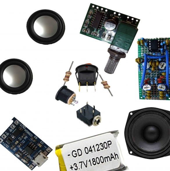
To do this, I needed:
- the first is the empty case of a portable stereo pair;
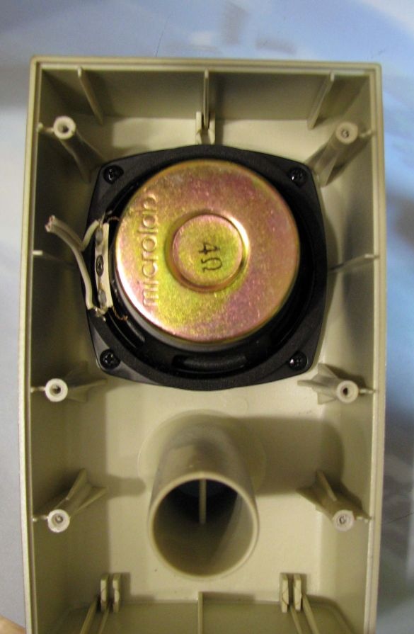
- The second, full-time dynamic head 4oma;
- the third, a lithium battery, any serviceable and of sufficient capacity, I have it from the tablet;
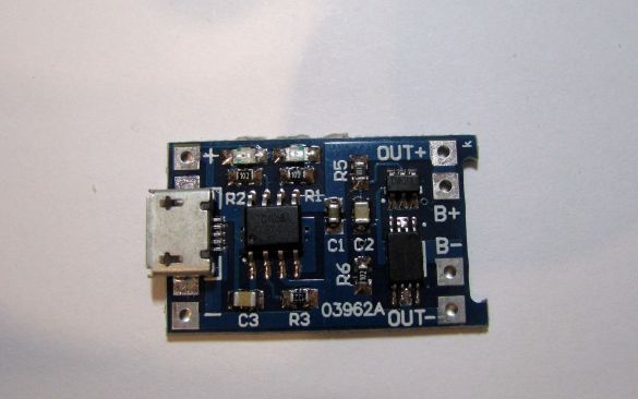
- a charge and battery protection board; I have it the simplest and only type that is available;
- two dynamic heads of 8th each and grids to them;
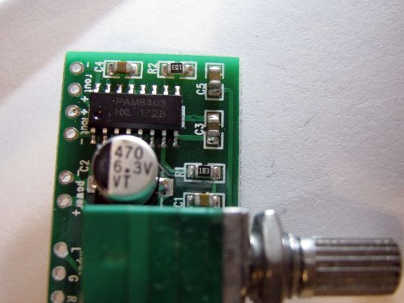
- ready-made digital stereo amplifier module;
- a 5.2 mm jack for connecting an external charging unit, a 3.5 jack for connecting an audio cord, a small-sized switch;
- two resistors of 2 kΩ each and two capacitors of 1000 μf;
- as well as the tone control I collected earlier.
You see the second column of two that I got for nothing. All electronics I stayed in another column (which I already gave), having previously built in the only one I had, the bluetooth module.
Tasks that I was guided in the development of the remaining column:
- I have a stereo amplifier module, but the speaker will be mono, I need to somehow dispose of the second, unused channel;
- it means that we are talking about two-way playback, I have additional speakers;
- messing around with the winding and calculation of separation filters - beyond my strength and understanding;
- I have two active stereo timbral units, and I collected them already last winter, but I didn’t attach them anywhere, - excellent;
- the time was three days, tomorrow, the column will already find the owner =)
External work.
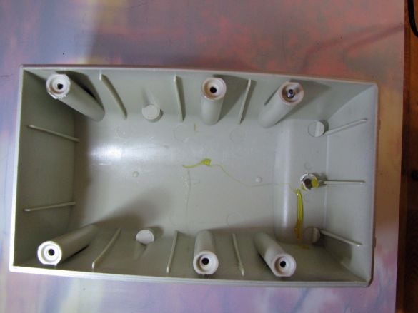
A disassembled column provides ample space
and
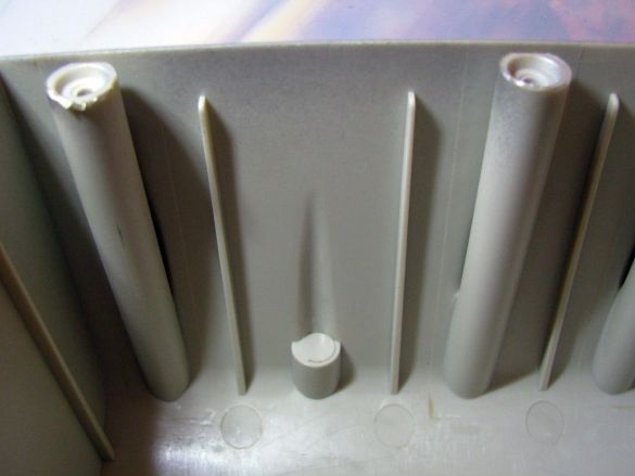
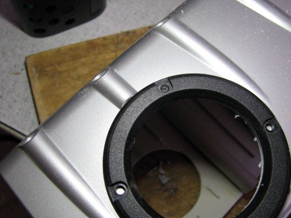
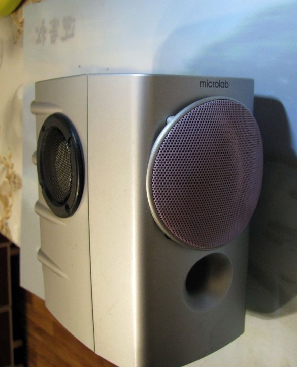
Pay attention to the previous photo. Additional speakers, I decided to install in the only places available at the ends of the column
They will be partially located on the site of false hull inflows
On the reverse side, there are no channels for inserting screws.
In general, I imagine it like this:
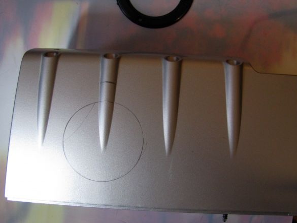
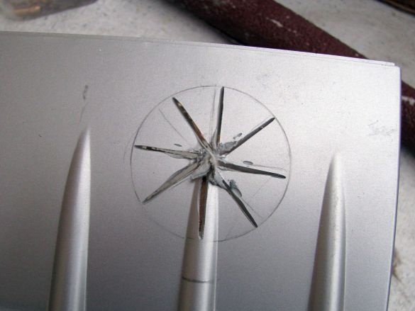
With a cutting disc, I made several cuts at once. I found that cutting sectors with a small circumference of the hole is much more convenient in terms of fear that the hand will lead the wrong way.
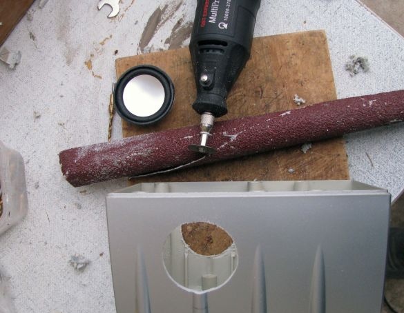
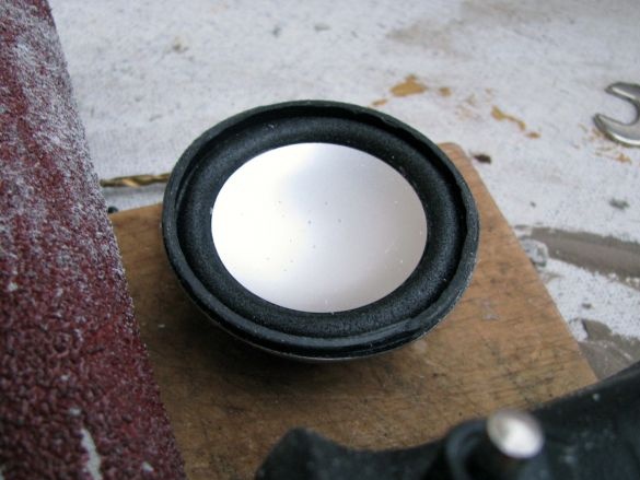
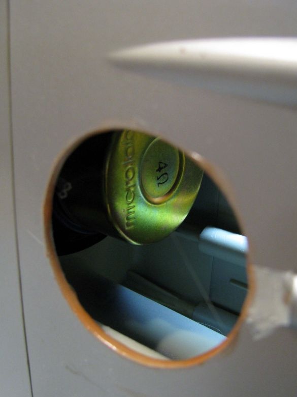
On the reverse side, I cut a hole in the same way, took the speaker and coiled it into a tube with a coarse-grained sandpaper, quickly adjusted the diameter of the hole to the outer diameter of the cardboard safety ring of the speaker.
AND
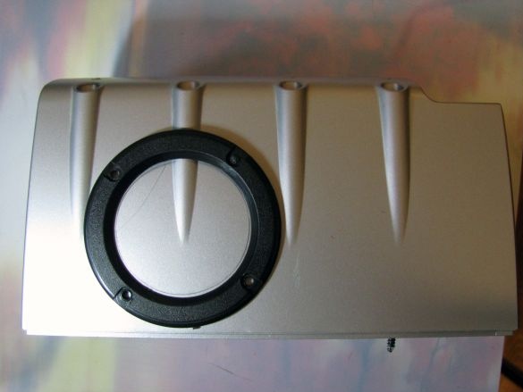
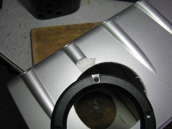
The end face of the cutting wheel, I rather melted than cut off the protrusion, which prevents the installation of a black pressure ring for the speaker grids.
It seems not bad for a collective farm =)
I pasted the speakers with Super-Monolith glue; it has the property of dissolving plastic during repeated and excessive application. On the inner circumference of the cut holes, I applied three standing glue with an interval of 20 minutes.
In the fortieth minute, I abundantly smeared the outer edge of the cardboard ring of each speaker with glue, and after another twenty minutes, firmly inserted both speakers into their intended places.
He quickly put down both the net and the ring, and figured it over his eye - did it happen as I intended - just like that =)
Tone control.
and
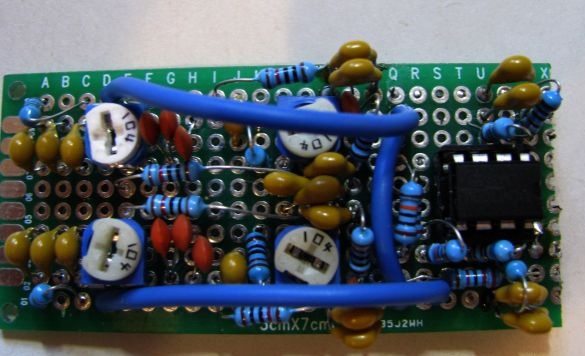
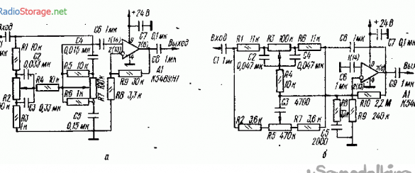
The scheme was taken from the amateur radio brochure. And over the past eleven years, this circuit has been assembled by me 5 times in the stereo version.
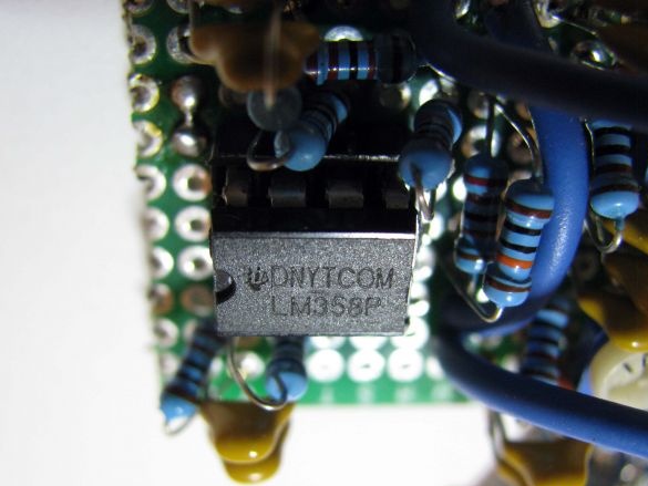
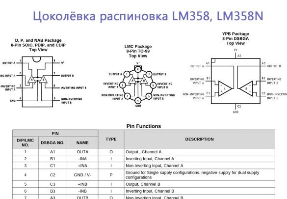
If the first three times, the circuits were assembled at k157ud2, then after so many years, I decided to use the relatively low-voltage lm358.
and
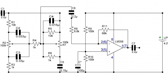
The scheme, taking into account unipolar power, naturally had to be adapted.
There is nothing special about her.
The only thing I notice is the mandatory use of a capacitor with a capacity of 470 microfarads and marked with an asterisk. When the whole circuit was assembled on the table, I connected the borrowed bluetooth whistle for a while, I heard strong interference. Not a digital blinking, namely a loud noise, and then I remembered the article I read not so long ago, I will give a link to it at the end. This article said that this capacitor attenuates the effect of amplified interference.
I didn’t have other capacitors, and I added them to the timbre block on the fly - the noise disappeared, but not blinking =)
Also, I soldered a 1000mkf capacitor to the power input of the tone block.
Charge charge.
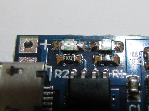
The simplest one, it indicates only the charge, with a red LED, and its end with blue. The inclusion of the load is not indicated in any way. But, I had no other controllers, only these.
I had to solder to the smd LEDs the wiring going to the two external LEDs that were glued into the holes on the outside of the speaker casing.
On the output load of the OUT module “+” and “-” I also hung 1000mkf.
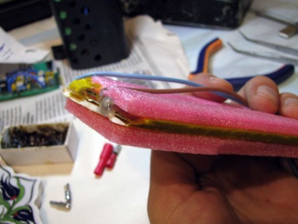
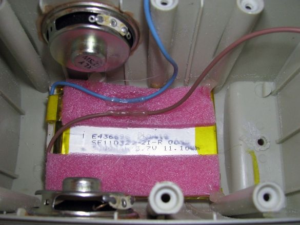
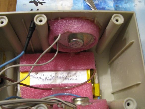
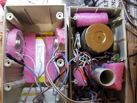
The battery itself is conveniently located on the back of the speaker. At first, I glued strips of foamed polyethylene to the battery with Super Monolith ...
... and then those strips, fixed with drops of hot hot melt glue, it seemed to me a bad idea to pour a hot liquid directly onto the battery.
Also, I decided that the only large speaker will be a low-frequency one, and the pressure it develops will modulate the diffusers of small speakers, I eliminated this by pasting the latter around the perimeter with strips of the same foamed polyethylene, the same “Super Monolith”
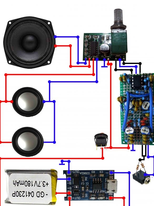
Visual connection diagram.
The speakers were tested and phased, all three must move their diffusers in phase. Two small speakers, each 8th, I connected in parallel.
On the rear roof there is a battery with a detachable connection and a charging socket, also with a detachable connection. Thus, I facilitated the assembly and setup.
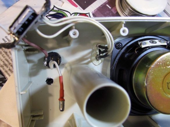
In the front half of the case, I placed a jack for connecting a stereo cable. Right on the socket contacts, I soldered a resistive adder of two resistors of 2 kOhm each, because I need one channel, not two.
Wrapped in a strip of foamed polyethylene, I placed a charge controller next to it.
Below it, the power switch is located, which is included in the OUT “+” gap of the battery charge module.
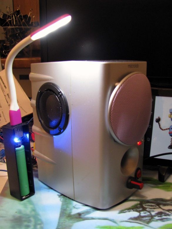
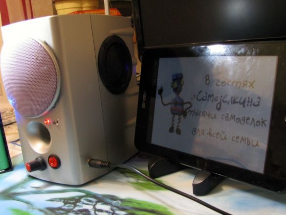
Here is what I ended up with:
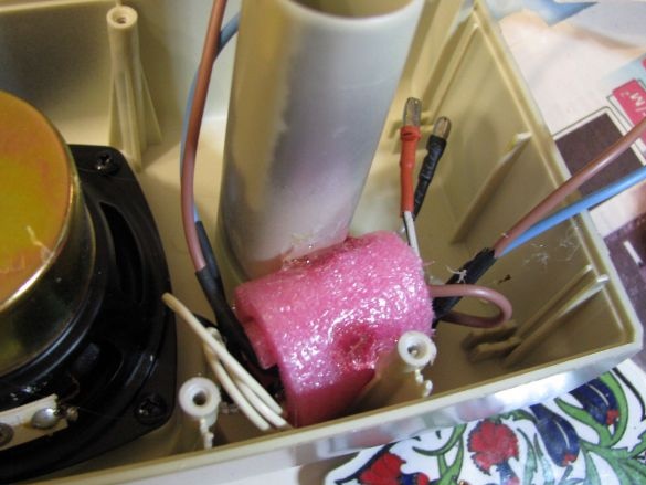
On top of the main speaker, there were unused power wires threaded through a ferrite ring - it touched the future, as soon as the bluetooth whistle arrives, I will withdraw the speaker and build it inside - such a danger exists.
On the right, there is a timbral block.
Below the pipe of the bass reflex, the power amplifier blocks on the PAM8403 are located. Directly to its power input, a capacitor of 1000 microfarads was also soldered.
Test
.I set the timbre by ear.At first, I tuned low, unscrewed both resistors to maximum, I removed the gain of the higher frequencies. In the same way, but in a mirror, I acted with a channel of higher ones.
I listened to the Madonna “Something to remember” and a strange sensation arose.
Putting on the stereo headphones, we listen and hear the work of the sound engineer who brings the composition together. We hear the depth that there is no way to hear in reality.
Not so long ago, I disappeared for an hour after hearing a symphony orchestra through the headphones on the “Culture” when I checked the equalizer on the tablet. You must admit that it is simply impossible to achieve such a clear localization of instrument sections just sitting in the hall and using only your two ears - but this is stereo.
In my case, this is total mono, and, turning the speaker towards myself with a small speaker, I had the feeling that I was looking into the concert hall through an ajar door.
It is often said that the sound is mono, as if if all the instruments and singers (or the singer) are locked together with them in a small box from which they scream.
Madona was not locked. She sang pathetically and velvety, namely I - peered through the doorway leading to the hall, where she stood at the microphone. =)
Well, actually, as I understand it, these are the advantages of multi-band playback. In addition, this balalaika will be used (most likely) in the kitchen, where there is no place for all texics-shmektis =)
AND
and
additionally:
- reference;
- on the chip K548UN1;
- Features of the use of operational amplifiers.


