Good afternoon, this time I want to share instructions on making a model of a heavy loader from Lego. Electrification as usual - Arduino. Model made on the basis of Lego 42079 HEAVY DUTY FORKLIFT. The brain of our model will be Arduino Nano v3, control via Bluetooth. For control, you can use an Android phone or tablet, or another Arduino board with a connected Bluetooth module.
Homemade Loader Video:
The list of everything you need is quite long:
- Lego Technic 42079 or 42029
- Lego Technic 42033
- Arduino Nano v3 AT Mega 328
- L9110S engine drivers 2 pcs.
- Servo SG-90
- Bluetooth module HC-06, HC-05 or equivalent
- Mini gear motor 50 rpm
- Mini motor gearbox 100 rpm
- Motor gearbox 6v 150 rpm
- White LED 2 pcs.
- Resistor 150 Ohm 2 pcs.
- Capacitor 10v 1000uF
- Single row comb PLS-40
- Inductor 68mkGn
- 4 NI-Mn 1.2v 1000mA batteries
- Connector dad-mom two pin to wire
- Homutik
- Wires of different colors
- Solder, rosin, soldering iron
- Battery A23 or A27
- Bolts 3x20, nuts and washers for them
- Bolts 3x40
- Bolts 3x60
Step 1 We assemble the case.
First you need to download the instructions Lego 42079 from the official website:
Having opened the Lego instruction, we collect all points from 1 to 40 inclusive. Do not put only gears (they will interfere), differential, knee shaft. Next, perform steps 56 to 75 inclusive. This should be the basis:
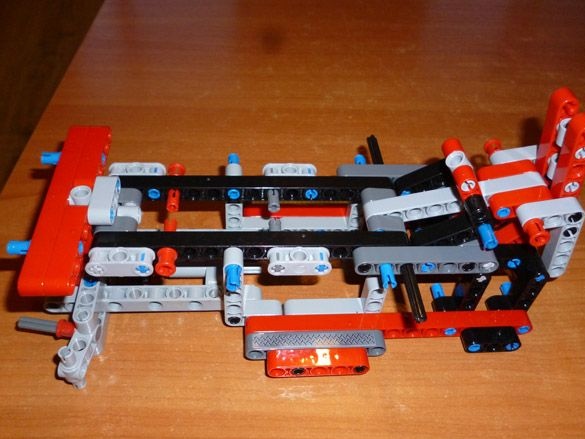
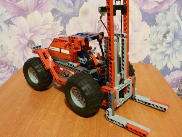
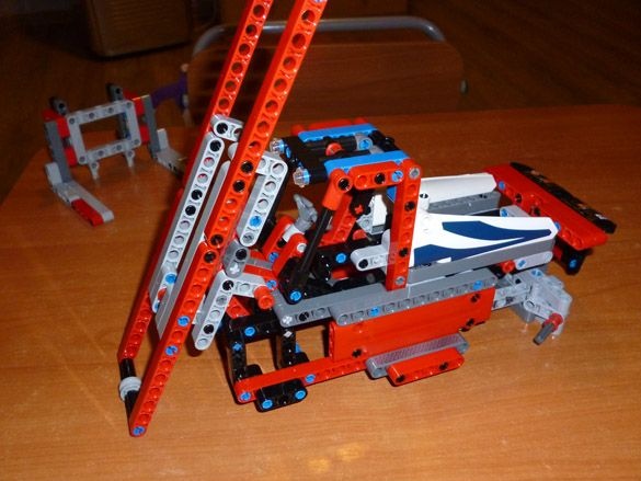
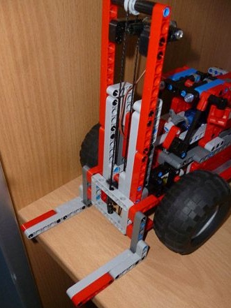
Then we perform steps 95 to 15 inclusive. We get the following:
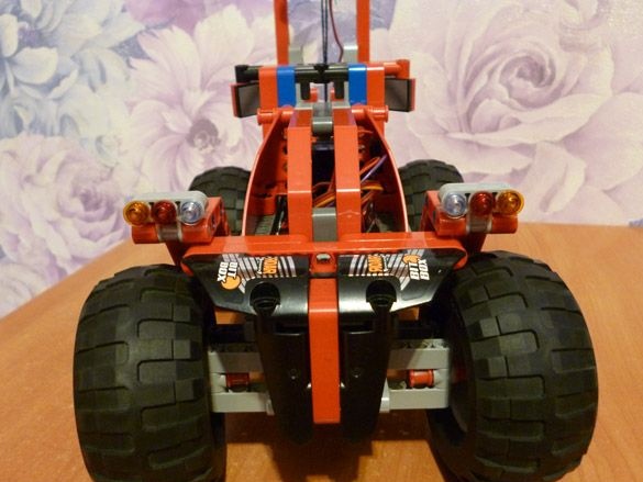
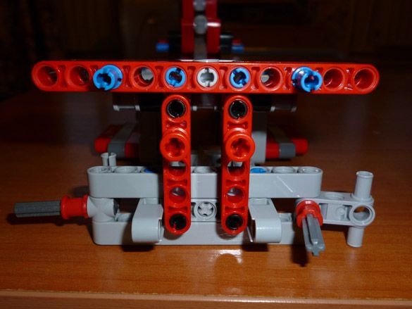
And front view:
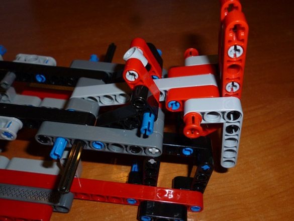
The tilt mechanism is slightly redone as in the photo:
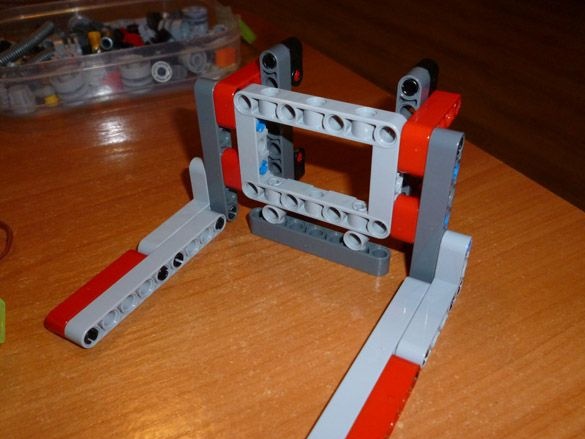
We collect the pitchfork, these are steps 183 to 192. We get:
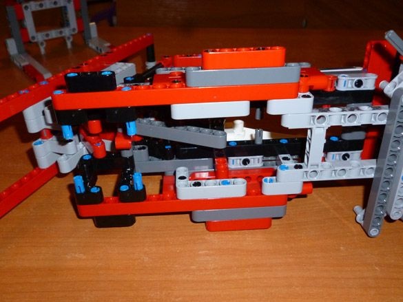
Add details according to Lego instructions steps from 116 to 158 inclusive:
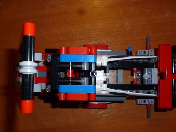
And below it looks like this:
You should also collect the pallet from the photo:
Step 2 Add Engines.
To implement the movement of the leading axis, we take a gear motor with a rotation speed of 150 rpm and a 6-volt motor. The output shafts of the gearbox are trimmed, giving them the form of a standard Legovsky part:
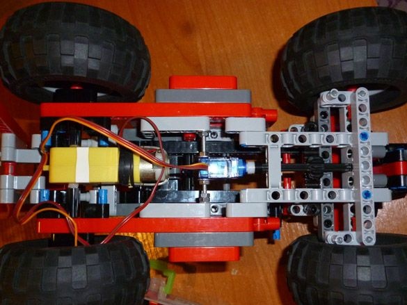
When making cross-shaped shafts, try putting on lego connecting sleeves. When the connecting sleeves are put on a sufficient depth, insert the gear motor into the housing, as shown in the photo. And immediately put on the wheels:
The motor gear itself is fastened to the body using 3x60 bolts.
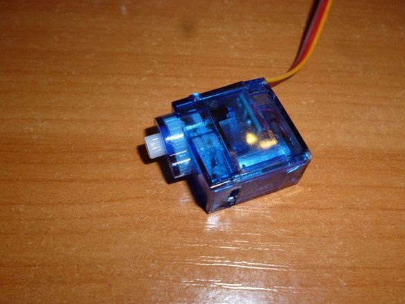
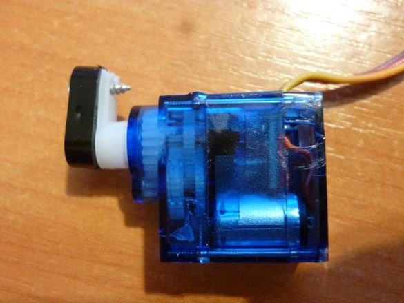
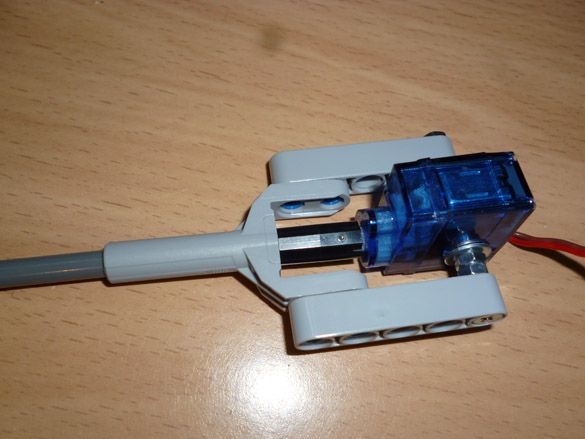
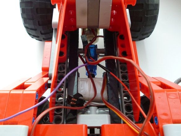
Now we pass to the rotary mechanism. For him we need a servo SG-90. It is better to choose with metal gears. To begin with, we need to cut off the protruding parts of the case, designed to mount the servo. And also make a through hole in the bottom of the case.You can use a 3mm drill, or just cut it with a knife, the main thing is to do it carefully so as not to damage the inside of the servo:
To connect with lego parts, take the smallest lever from the servo and screw the small lego part to it. It should look like this:
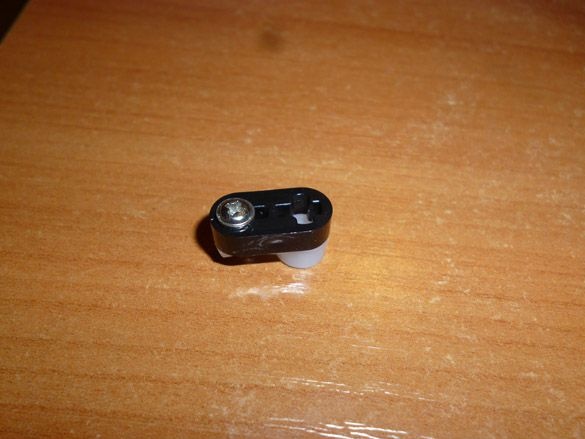
We put the resulting part on the servo:
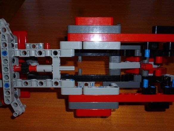
We fix the servo in the lower part of the model, approximately in the middle. For fastening we use a 3x60 bolt. Then we insert the lego shaft and put on it a gear that rotates the wheels:
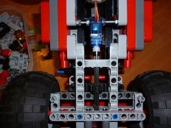
We put on all four wheels:
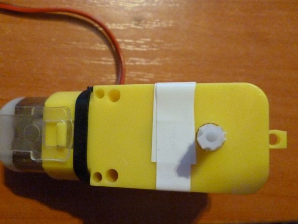
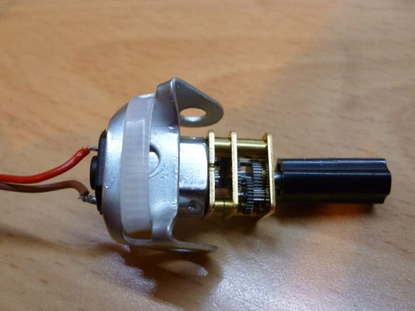
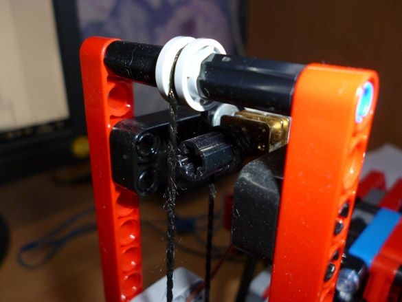
We pass to the lifting mechanism. For it we take a mini gear motor with a speed of 50 rpm. The output shaft of such a motor gearbox is 3mm, it is well suited for the Legovsky connecting sleeve. It is only necessary to insert a piece of a match for fixation. And also bend the part from the metal constructor, as shown in the figure, for attaching the motor to lego:
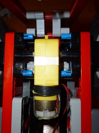
Now put the mini gear motor in the upper part of the lifting mechanism, as shown in the photo. We take a thick thread, throw it through the upper roller, then we wind it onto the connecting sleeve from the motor (three to four turns) and pass it through the lower roller. It should be like this:
We put the forks on our design, and we tie the ends of the thread to the forks:
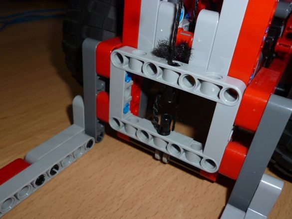
The entire hoist assembly looks like this:
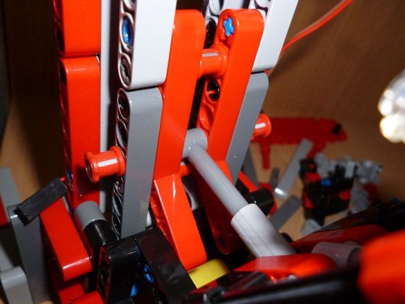
Now let's move on to the tilt mechanism. For him, we take the servo SG-90. Preferably with burnt electronics. We disassemble it and take out the controller board, solder the wires directly to the motor. We disassemble further and take out the largest gear, cut off the restrictive projections from it from below and put it in place. It is also necessary to cut off the tabs for mounting and make holes, as in the first servo drive. The converted servo is attached to the legov details:
We put the mechanism inside the cab:
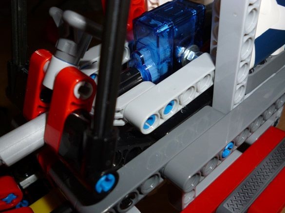

And its end is attached to the lifting mechanism:
Step 3 preparing the programming environment.
Editing and filling sketches is done through the Arduino IDE. This program must be downloaded from official site and install.
Then you need to add two libraries to the programming environment that are used in the sketch. Servo.h is a library for working with servos, and SoftwareSerial.h for creating a software channel for communication with the Bluetooth module:
Downloaded and unpacked archives should be moved to the “libraries” folder located in the folder with the Arduino IDE installed. You can go the other way, namely without unpacking the archives, add them to the programming environment. Launch the Arduino IDE, select Sketch - Connect Library from the menu. At the very top of the drop-down list, select the "Add .Zip library" item. We indicate the location of the downloaded archives. After all the steps, you need to restart the Arduino IDE.
Step 4 Bluetooth module.
We will take one of the most affordable Bluetooth modules for today - HC-05 or HC-06. They are full both in Chinese stores and on the Russian market. They have not so many differences: NS-05 can work both in master mode (slave) and in slave mode (master). NS-06 is only a slave device.
Briefly the characteristics of the modules:
- Bluetooth chip - BC417143 manufactured by
- communication protocol - Bluetooth Specification v2.0 + EDR;
- radius of action - up to 10 meters (power level 2);
- Compatible with all Bluetooth adapters that support SPP;
- The amount of flash-memory (for storing firmware and settings) - 8 Mbit;
- the frequency of the radio signal - 2.40 .. 2.48 GHz;
- host interface - USB 1.1 / 2.0 or UART;
- power consumption - the current during communication is 30-40 mA. The average current value is about 25 mA. After the connection is established, the consumed current is 8 mA. There is no sleep mode.
For the correct operation of the module, you need to configure before connecting. The setting is done by giving AT the commands entered in the terminal window. We will customize the HC-05. For other modules, commands may be different. We will connect the computer and the Bluetooth module through Arduino. Fill the following sketch in arduino:
This sketch is needed to send AT commands to the Bluetooth module. Arduino simply transfers everything written in the terminal to the Bluetooth communication module. Now and in the future we will connect the module through the SoftwareSerial library. The link to download it and the installation instructions were in the previous step.At high speeds, the library is unstable. If you encounter problems with the communication speed, you can connect the module directly to the Arduino's RX and TX contacts. Do not forget to correct the sketch in this case. In this case, we will work with the module at a speed of 9600. So, after filling in the sketch, open the terminal window and enter the following commands:
“AT” (without quotes) the answer “OK” should come (it means everything is connected correctly and the module is working)
“AT + BAUD96000” (without the quotes) the answer “OK9600” should come.
If you have the right answer, go to the next step.
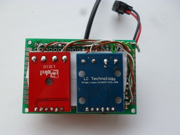
Step 5 Managing electronics.
To revitalize our model, we will use the Arduino Nano v3 and the Bluetooth module, as well as two L9110S engine drivers.
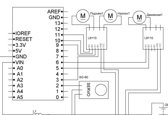
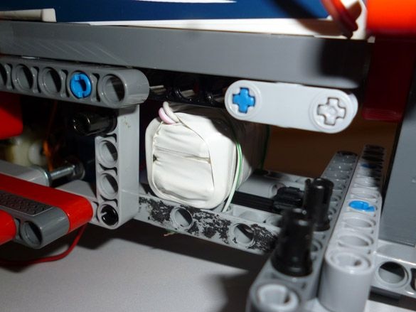
To connect the components, we will use wires with Dupont female connectors at the ends. For nutrition, you can try two options. First: 6 NI-Mn 1.2v 1000mA batteries connected in series, then both Arduino and motors are powered by them. For Arduino, a 10 V capacitor with a larger capacity, as well as an inductor, must be included in the power circuit. This is necessary to stabilize the power of the microcontroller. For flashlights, connect the anodes of two LEDs to 4 pin Arduino, cathodes to GND. Resistors should be selected for the LEDs used. The second option: separate food. Then for engines we use all the same batteries wound with electrical tape:
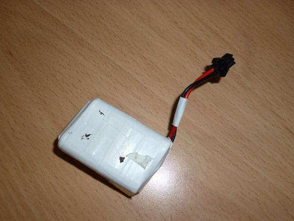
And for Arduino, the battery is A27 or A23:
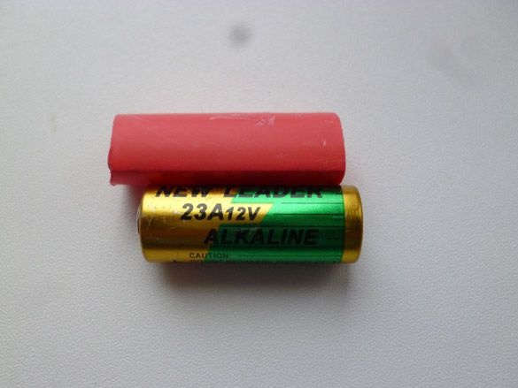
For reliability, place the battery in heat shrink.
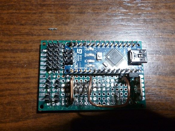
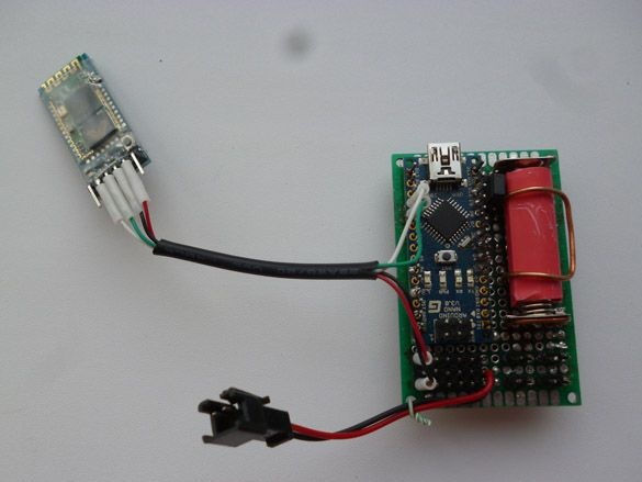
Of course, you can connect everything according to the scheme simply on the "weight", but it is better to do it all on the circuit board. We solder the Arduino Nano from above, a place for the battery and conclusions for powering other elements:
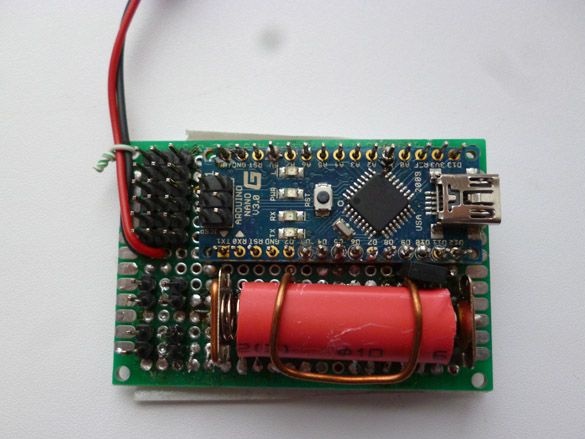
We put the battery in its intended place:
From below, you can solder everything in tracks, but faster just with wires in insulation:
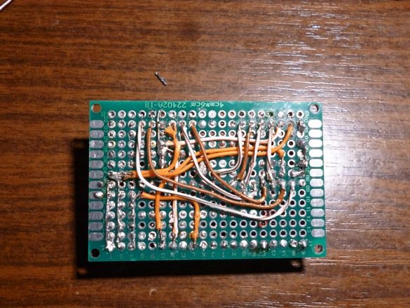
We attach and solder the driver contacts to the bottom of this board:
It turns out compact and reliable wires.
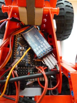
All electrics are placed behind the cab:
We fix the batteries below:
We connect the Bluetooth module as follows:
Arduino Nano - Bluetooth
D7 - RX
D8 - TX
5V - VCC
GND –GND
And we place the board together with the module in the place intended for them:
Step 6 Control Panel Setup.
As a remote control, you can use an Android phone or tablet, a computer running Windows or a hand-made remote control on arduino. Let's start with the version on Android, for this you will need to install the robot control program via Bluetooth. Enter “Bluetooth Arduino” in Google play and install the program you like. I recommend BT Controller. Then, through the Android settings, we establish a connection with the Bluetooth module. The password for the connection is “1234” or “0000”. Next, configure the program for the appropriate commands. The list is below.
The next option is a Windows computer. You can use the terminal window to send commands or use the convenient Z-Controller program. Select the port (com port through which the connection is made) and configure the keys for the commands. The setup is simple and won't take you much time.
And finally, the third option, and in my opinion the best, is the use of a physical remote control, since then you feel the click of buttons. I advise you to make a remote control, following mine instructions.
And add to it Bluetooth module.
The management commands are as follows:
W - forward
S - back
A - left
D - right
F - stop
G - steering wheel
K - headlights
L - headlight off
R - lift up
E - downhill
Q - stop lift
T - tilt on yourself
Y - tilt away from you
H - stop tilt mechanism