
I think that each of you who played games, sooner or later wanted to use cheats. This also affected the author (YouTube channel "Open Frime TV") of this homemade product. As a result, we got such an installation that plays in your place.
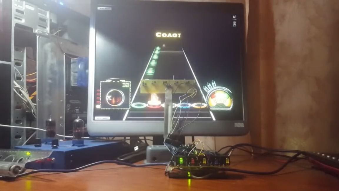
Since childhood, the author loved to play different games, and one of them was “Guitar hero”. The author still plays it, it helps to relax after a hard day, as well as to train the reaction.
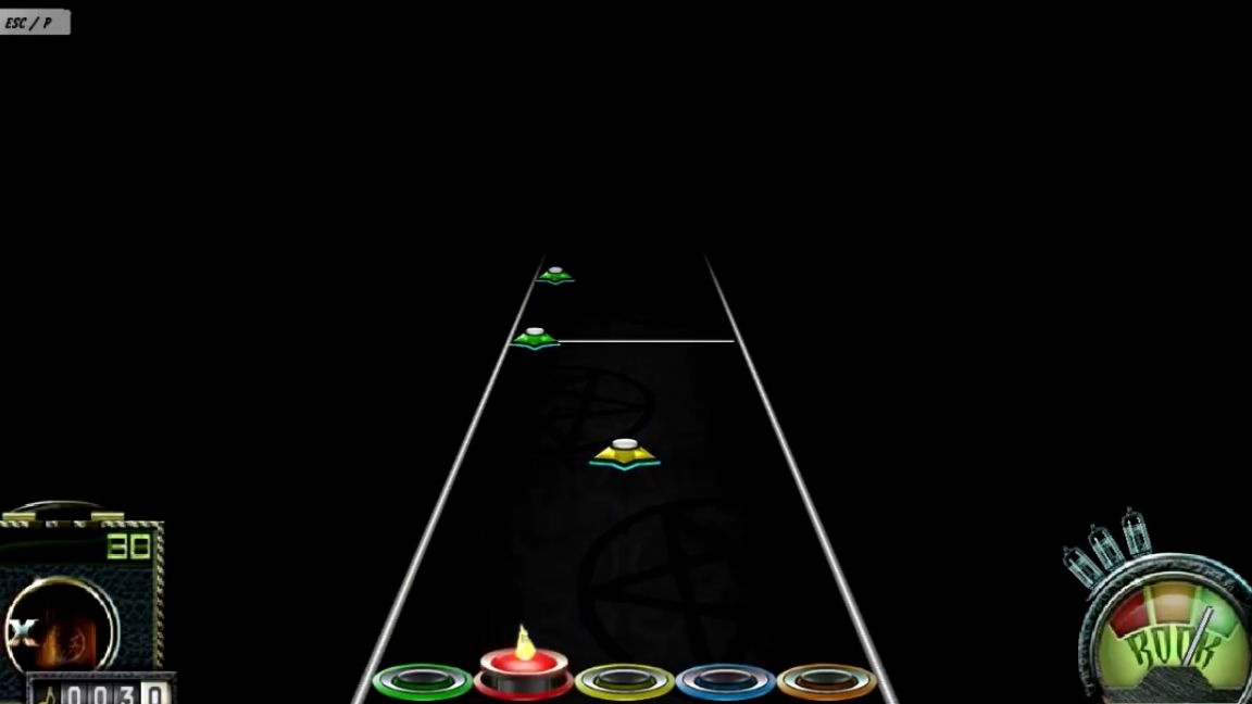
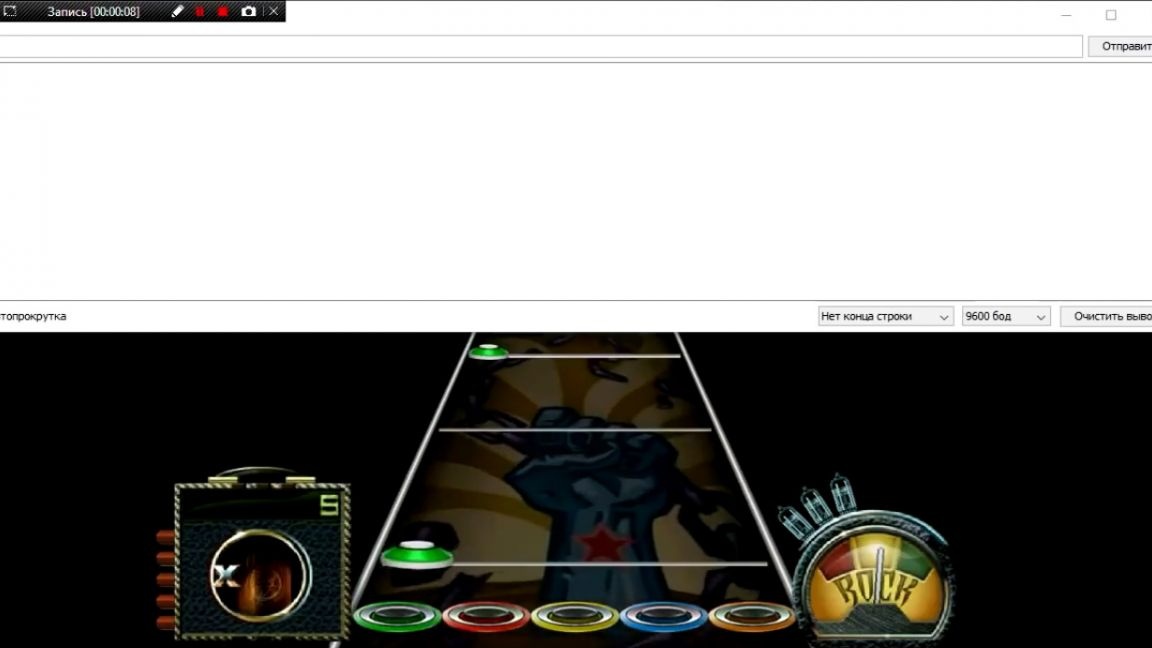
As you understand, in this game you need to play songs on the guitar, getting into the notes. When a note approaches approximately this area, you must press the corresponding key.
Also in this game there are very complex songs that are almost impossible to pass. It was then that the author came up with the idea to assemble a device that would follow a note suitable for a certain zone and, in accordance with this, press the desired key. Here you can immediately make 2 comments. First: of course, it is easiest to do this generally programmatically and use it as a cheat.

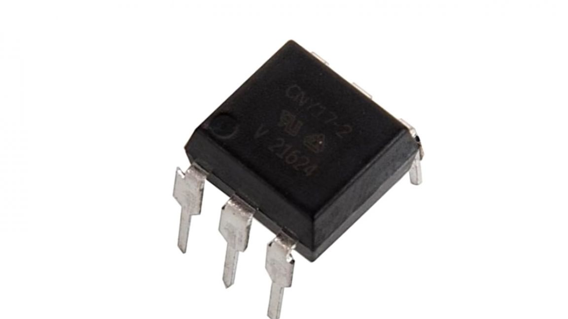
And the second, even if it is not done programmatically, it is extremely undesirable to use a relay, it is better than an optocoupler or something else.
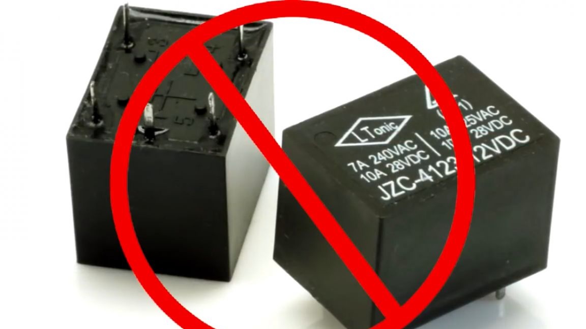
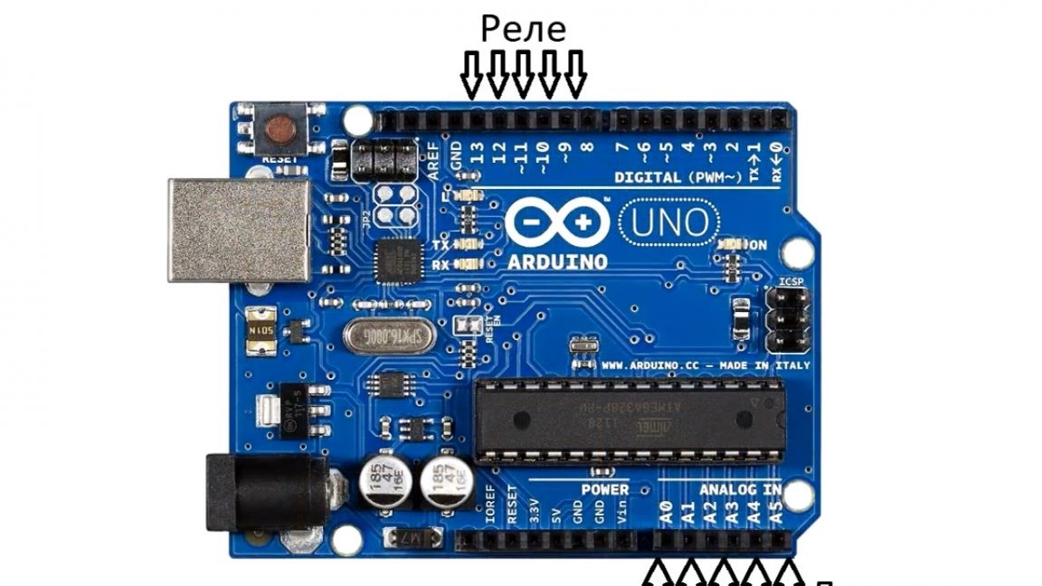
Now in order. If you use the program code, then in this game you can easily catch a ban. The mechanical cheat is almost impossible to calculate. Now about the relay. His clattering creates an indescribable atmosphere and the full effect of presence, so it was decided to dwell on them. So the task is clear. Now you will see how the author of this homemade robot managed to implement it. Everything is simple. Arduino Uno drives this whole thing.
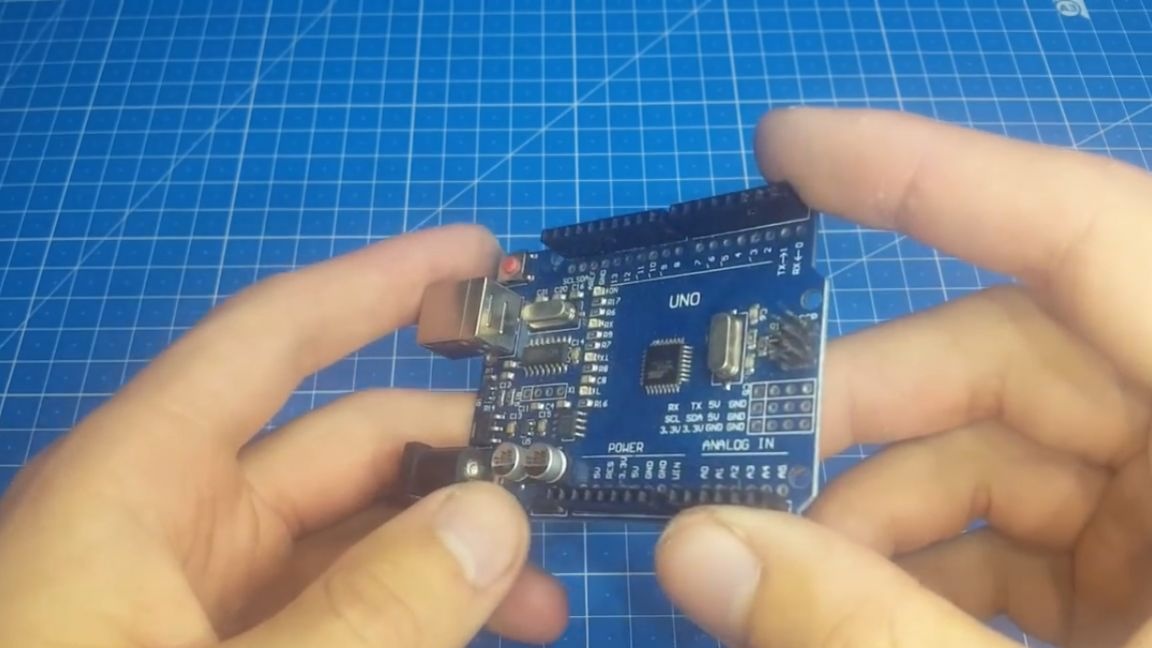
And there are two reasons for this. Firstly, because the Arduino Uno board was already in the possession of the author, and secondly, I did not really want to bother and do this homework on operational amplifiers, since arduino much easier just by changing the values in the code.
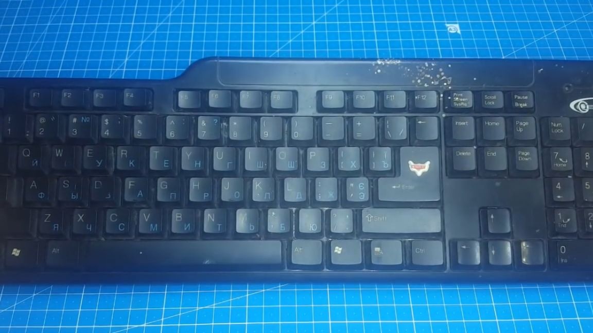
Also, to create a home-made robot bot, we need an old computer keyboard, to which we will connect and press buttons.
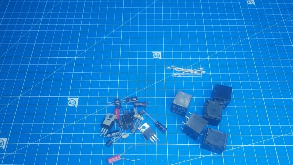
We will also need reels, phototransistors and various trifles, you will see this later.
Why did the author decide to use phototransistors? The answer is this, at first he made a robot using photoresistors, but then it turned out that they were too slow and did not have time to work out.
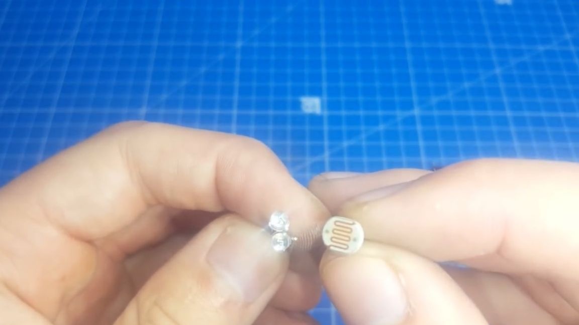
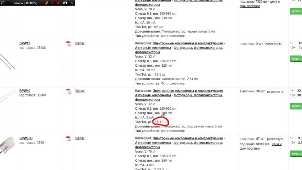
At the phototransistor, the switching speed is only 0.01 seconds, and this gives us excellent performance.
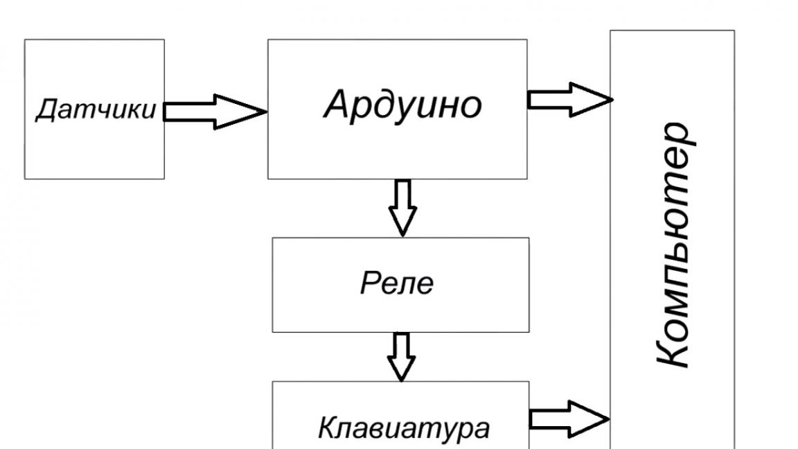
Now go directly to the device diagram. Let's look at the flowchart first.

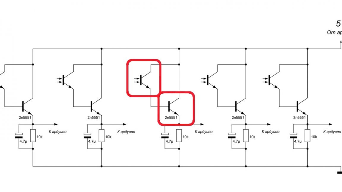
As you can see, everything is pretty simple here. And now, separately, we consider each block. The sensor circuit looks like this.
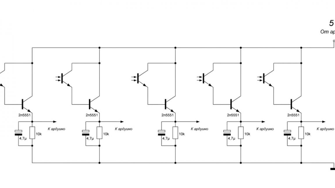
Each photoresistor is combined with an ordinary transistor to increase the gain, and there are also pull-up resistors and smoothing capacitors to prevent false alarms.
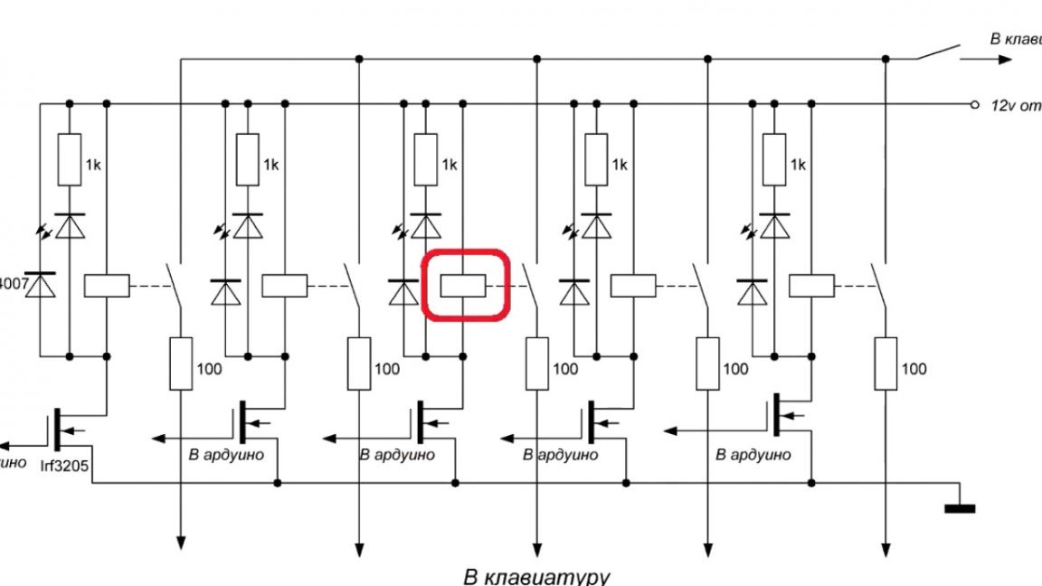
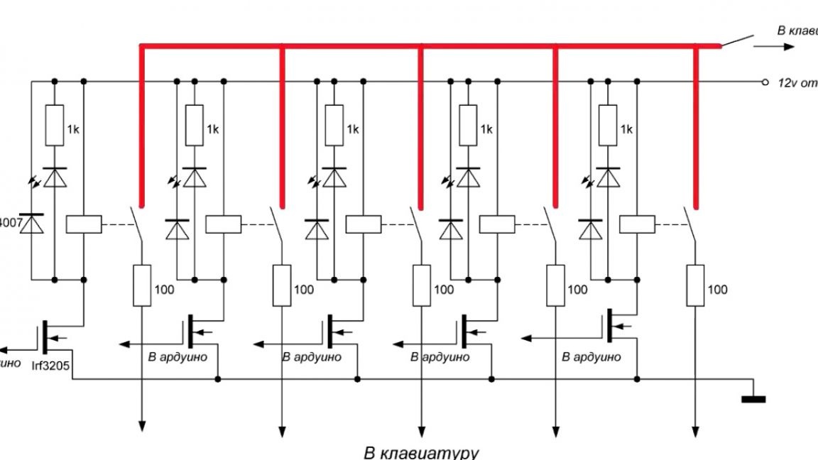
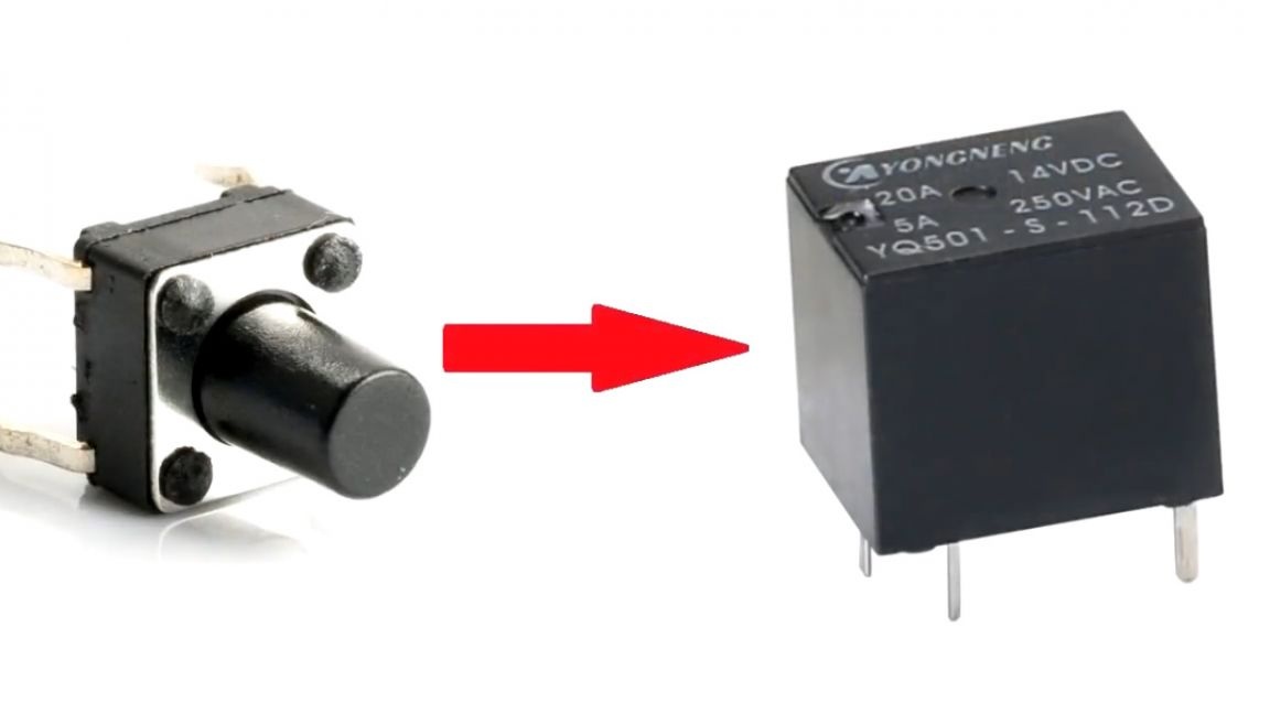
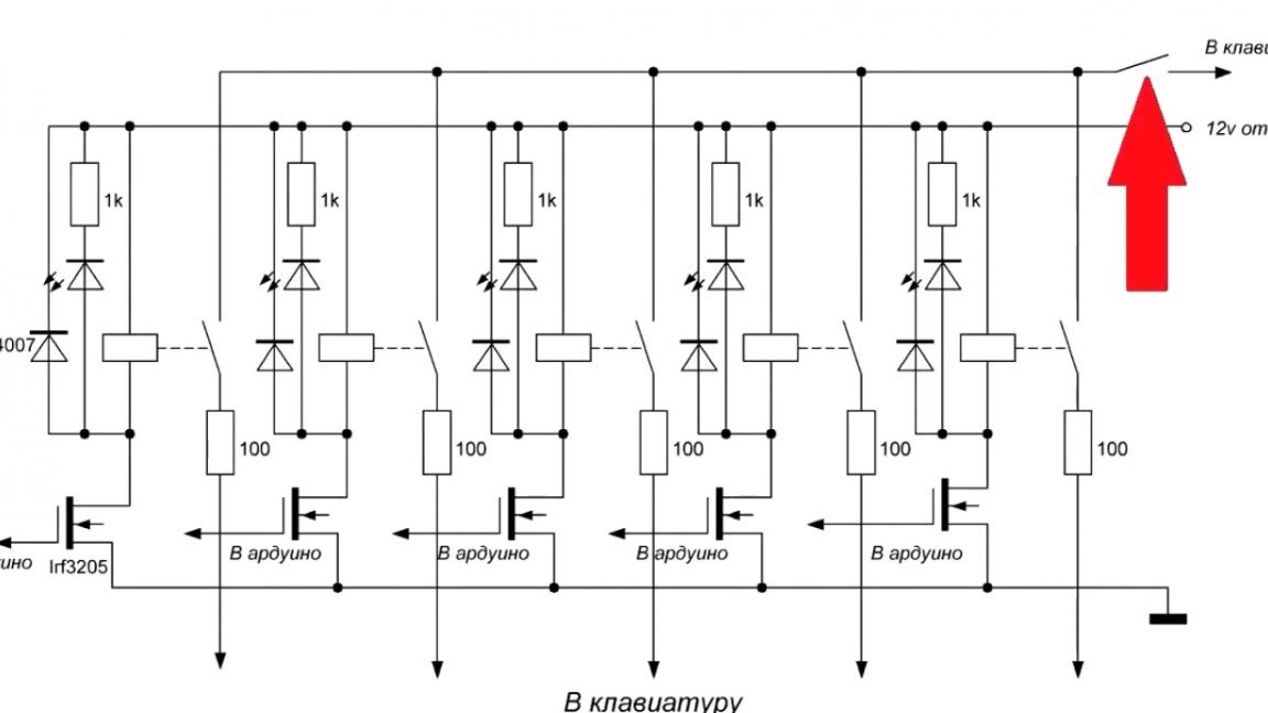
The second scheme is a rely scheme.
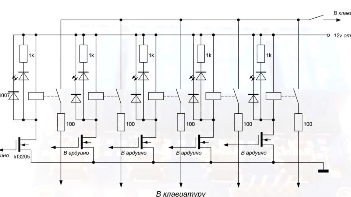
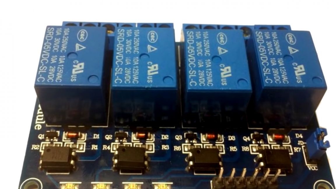
Instead, it was possible to take a ready-made module, but what kind of radio amateur are we then, if we do not do it ourselves? do it yourself.
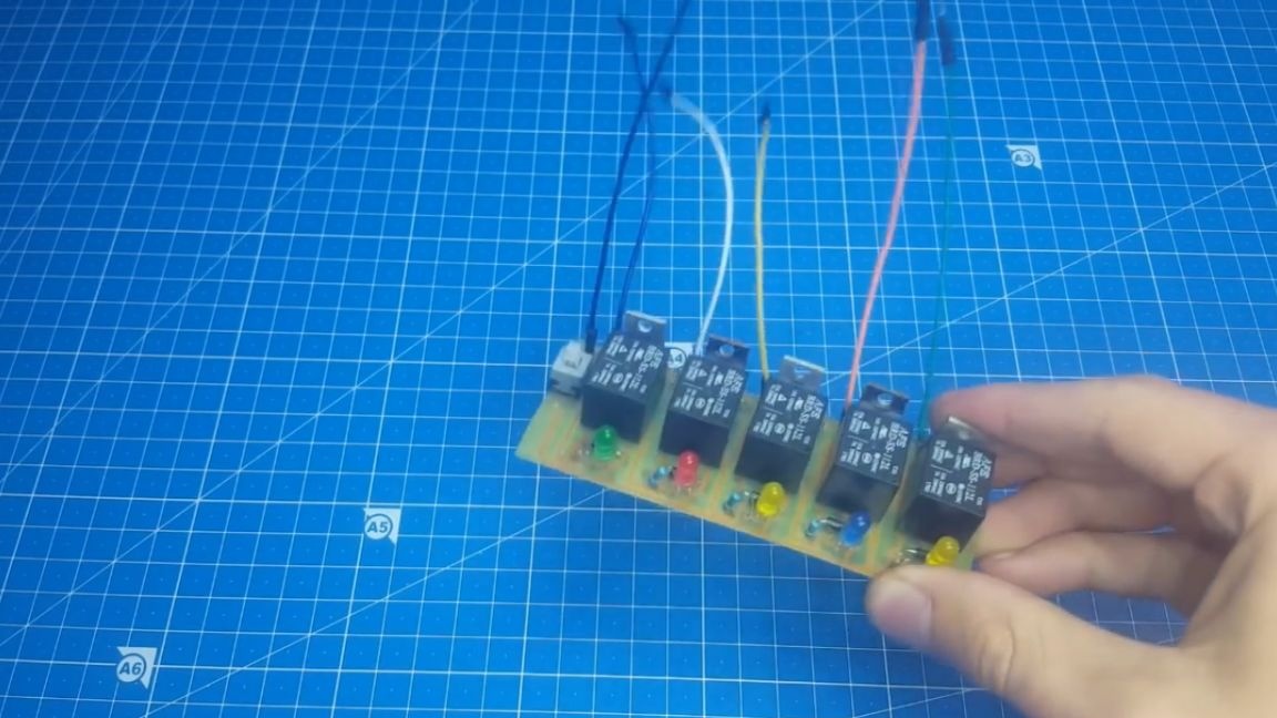
In this diagram, you can see mosfets that control the rail, protective diodes, as well as LEDs (it was decided to put them at the very end to simplify device setup).

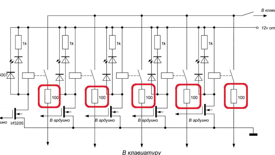
Also here we see an incomprehensible track and resistors, let's figure out what it is.
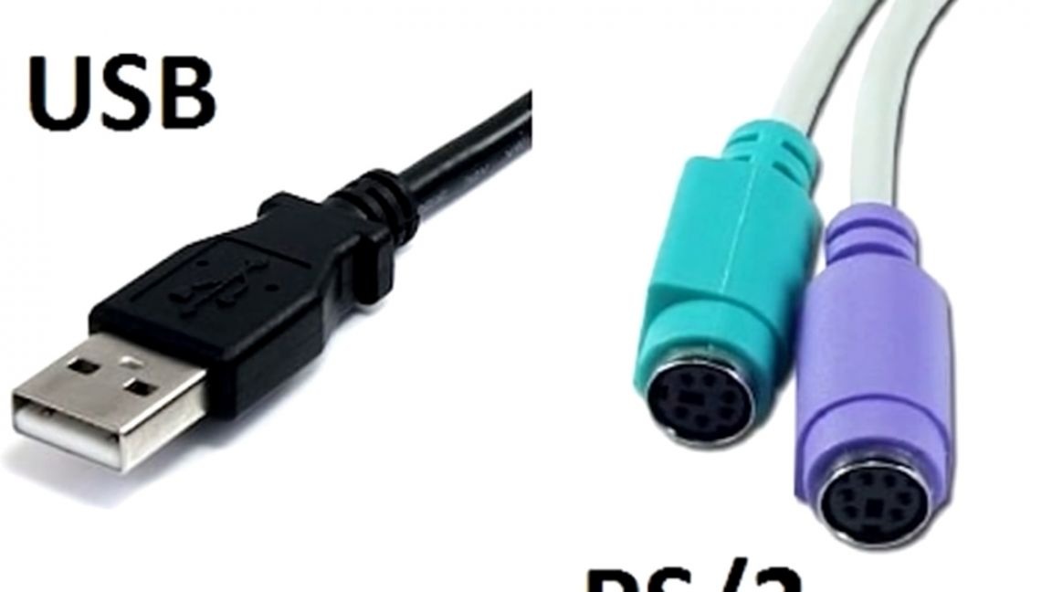
So, as mentioned earlier, for the manufacture of this homemade product we need an old keyboard, it can be used with a different connection interface (usb or PS / 2 is not important).
From it you need to get the module.
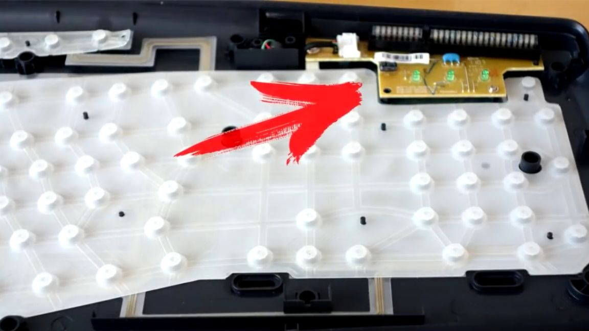
Now you need to solder the reels instead of buttons, for this you need to understand how the keyboard works.
The platform itself with the keys contains tracks, but these tracks are not easy, but with resistance.
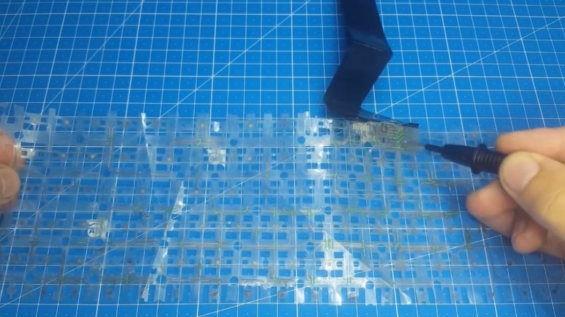
And let's say if we close at this point, then the resistance is 50 Ohms:
And at this point it’s already 100 ohms.
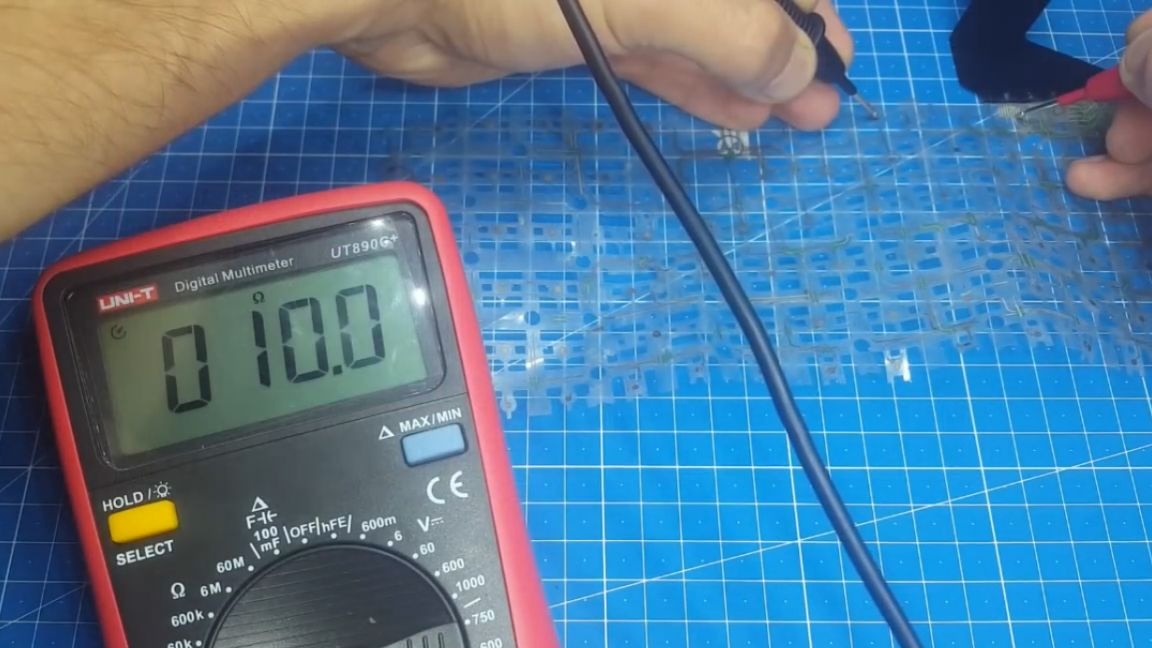
The module sees this and provides information to the computer. We need to replace these tracks with resistors. To do this, measure the resistance of the track.
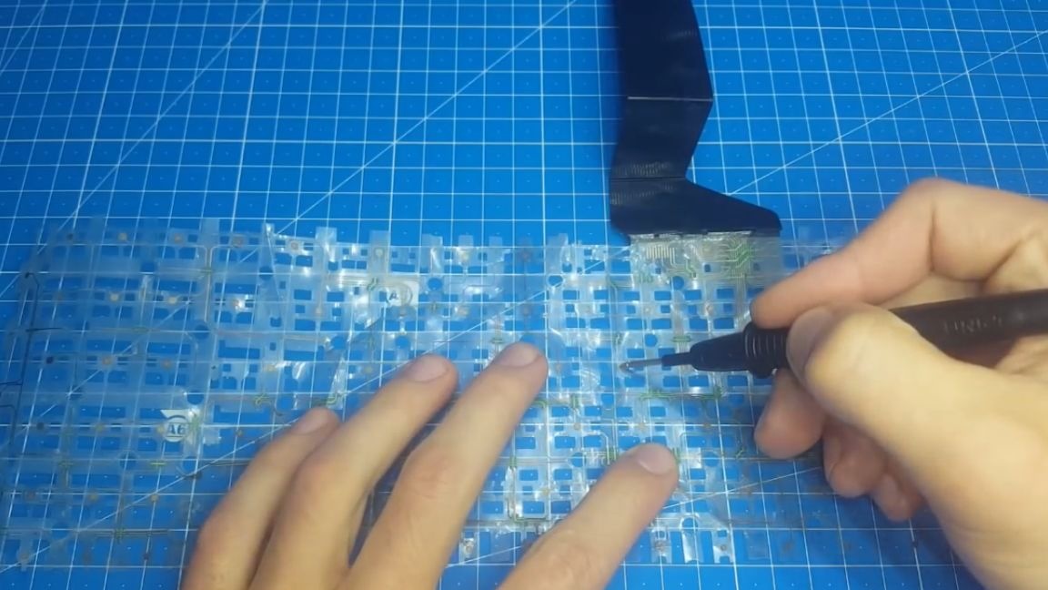
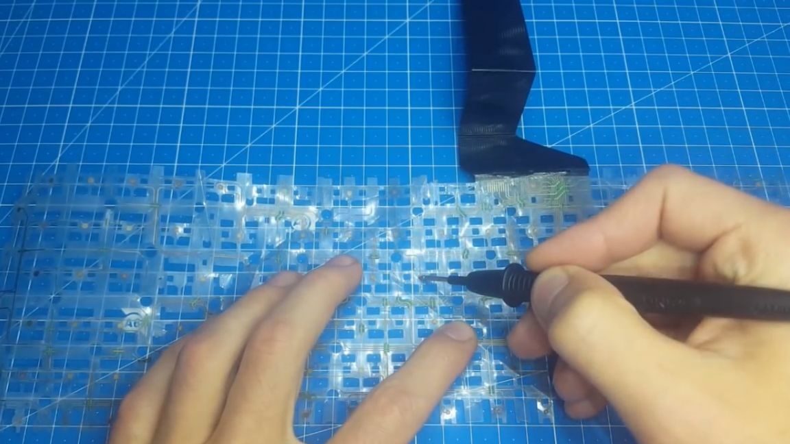
Then we connect the keyboard to the computer, take a suitable resistor and start connecting it to different points, depending on which key we are pressing.
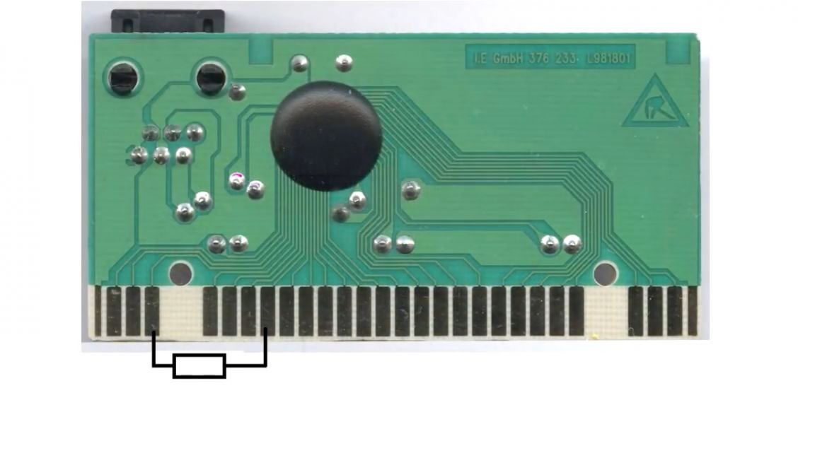
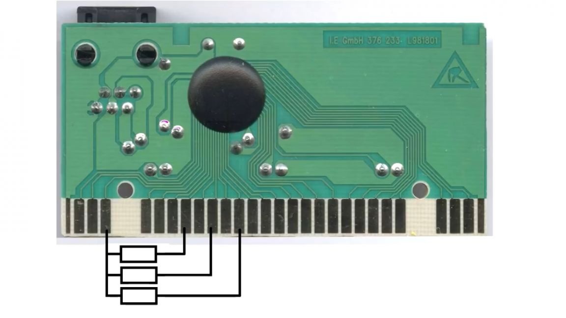
Here it is advisable to find a track to which you can connect 5 keys at once.
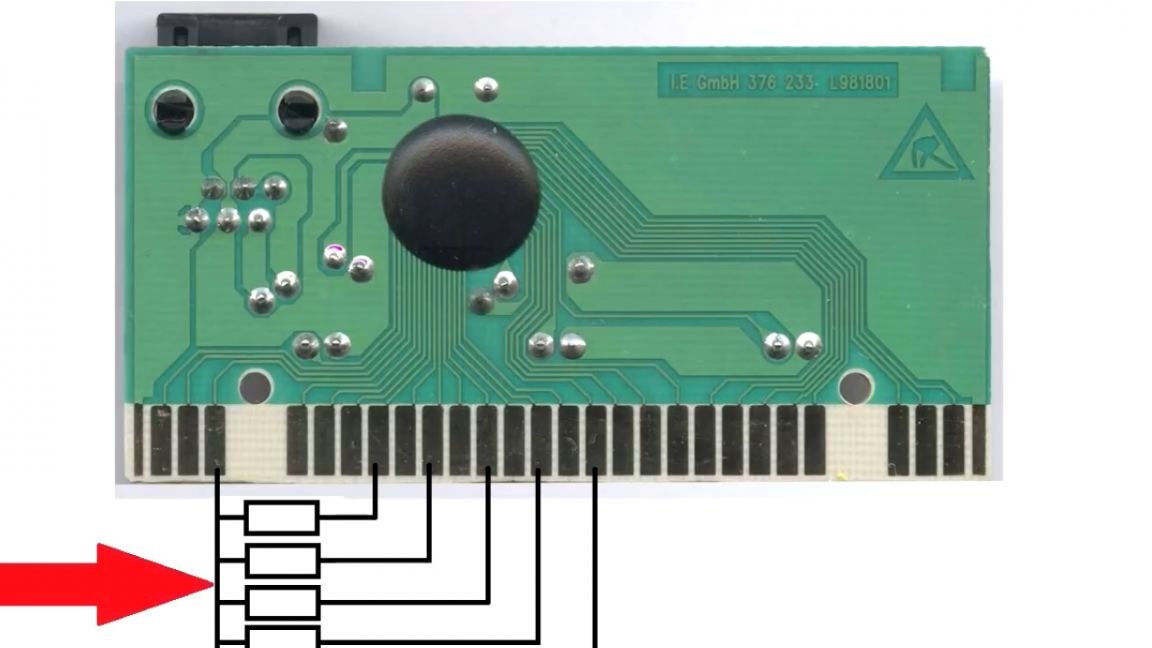
This is done in such a way that you can turn off the keyboard after the game is over, otherwise the reels, closing in the light, begin to clap all the keys, creating wild chaos.
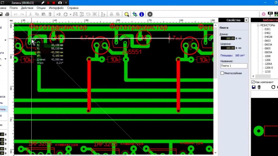
And now, when we figured out the circuits and the connection, it was time to make the printed circuit boards. For convenience, of course, it could be done on a breadboard, but it seemed to the author easier to sketch a signet, rather than being tormented with breadboard.
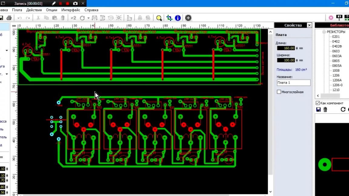
So, the board is drawn. The author selected the location of the photoresistors for his monitor, for another monitor you need to either increase or decrease the distance.
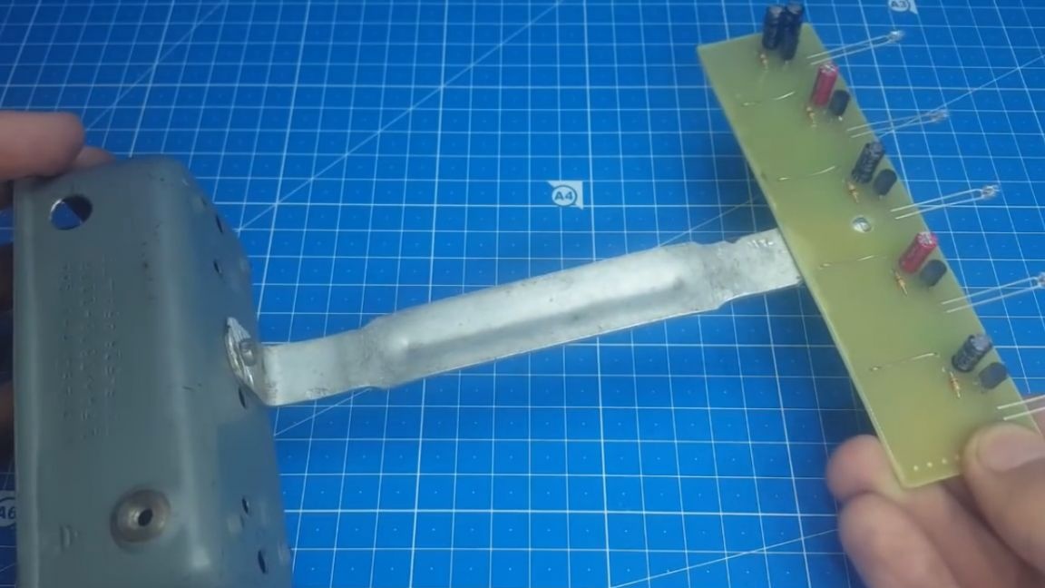
The resulting boards are sealed, all this is done elementary. We collect individual blocks.
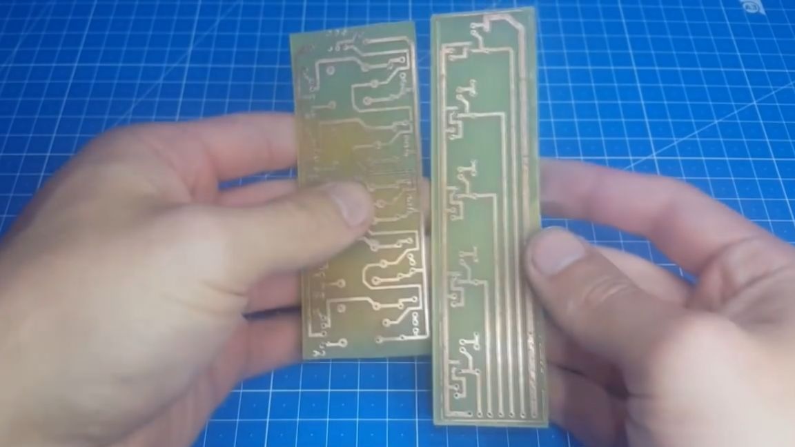
As you can see, the author made such a stand for the photoresistors so that they are at the right level.
It remains to connect the blocks into one device. We collect everything as in the figure and now we can proceed to the arduino firmware code.
To do this, we need this sketch.
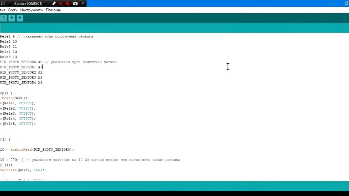
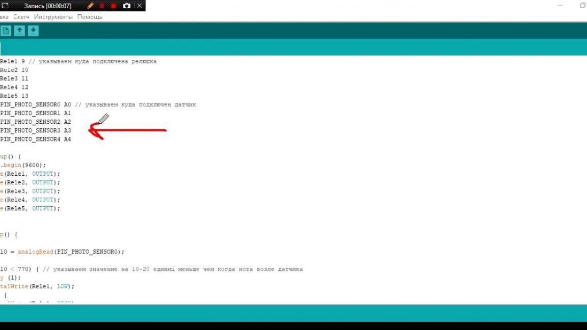
Here we indicate where the light sensors are connected:
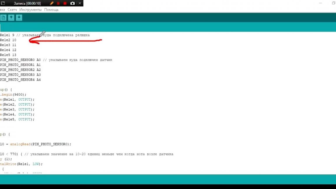
And here, where the relays are connected:
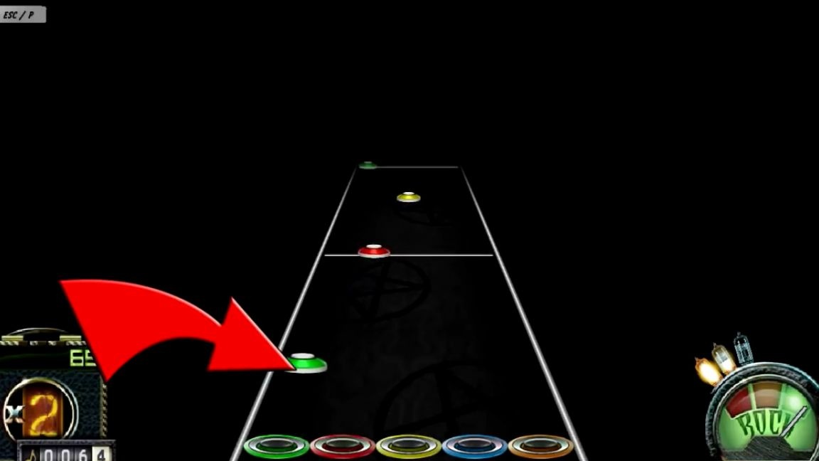
Now it remains to make the adjustment. To do this, look at the port monitor for each sensor with a dark screen and when a note passes through the sensor.
It remains only to drive here the value that was when the note passes the sensor.
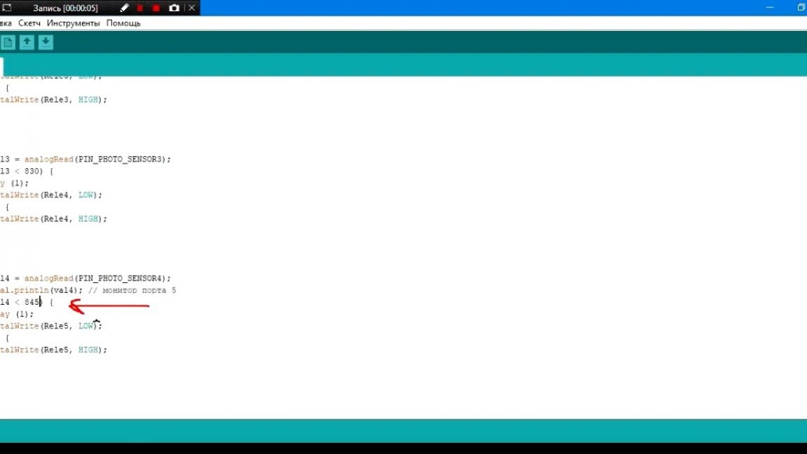
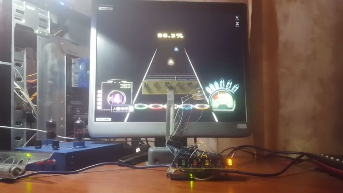
But that’s all. Fill the sketch into arduino and you can test it.
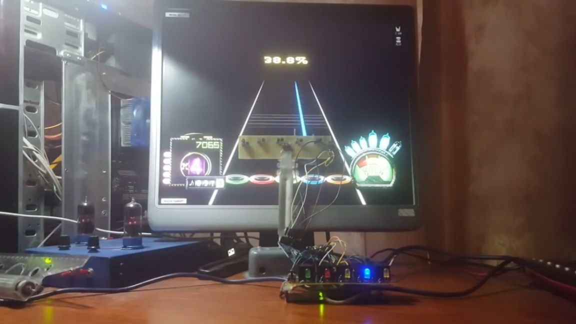
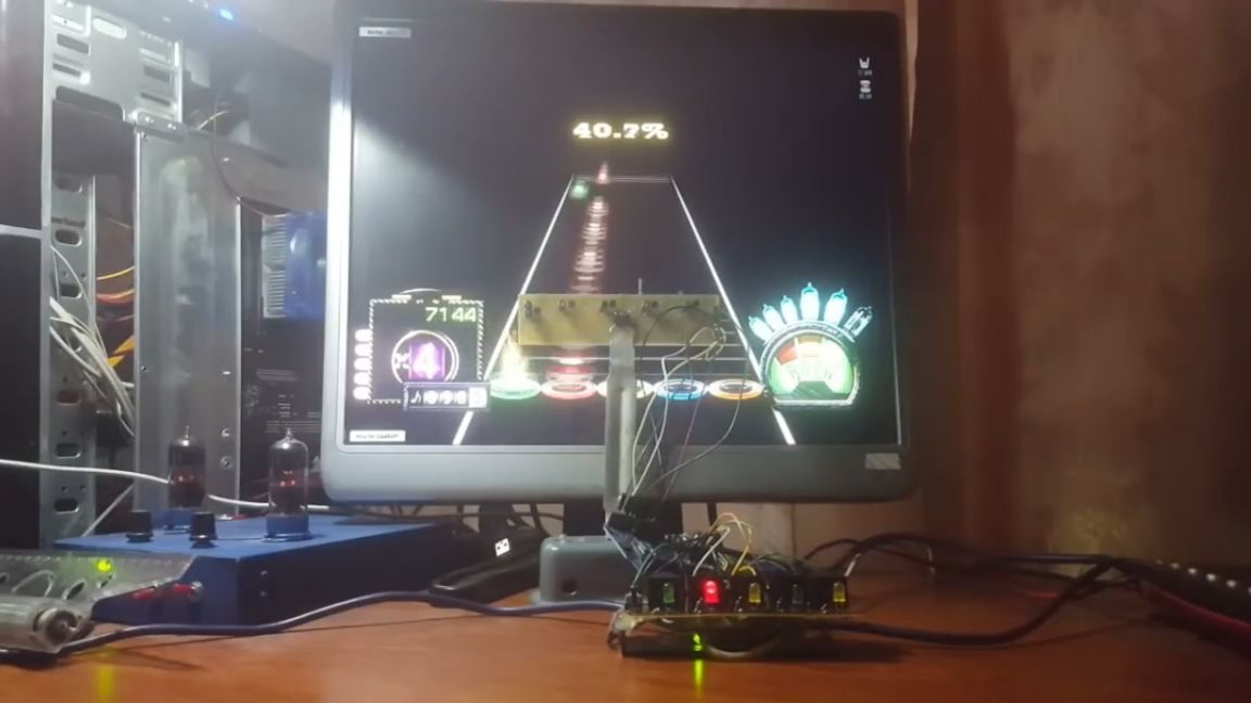
As you can see, the device does an excellent job. Well, that’s probably all. Thank you for attention. See you soon!
Video: