
Today we will manufacture one very important tool for electronic engineers. We will make a power supply with adjustable voltage and current. The author of this homemade product is Michael (YouTube channel Arturos TV).
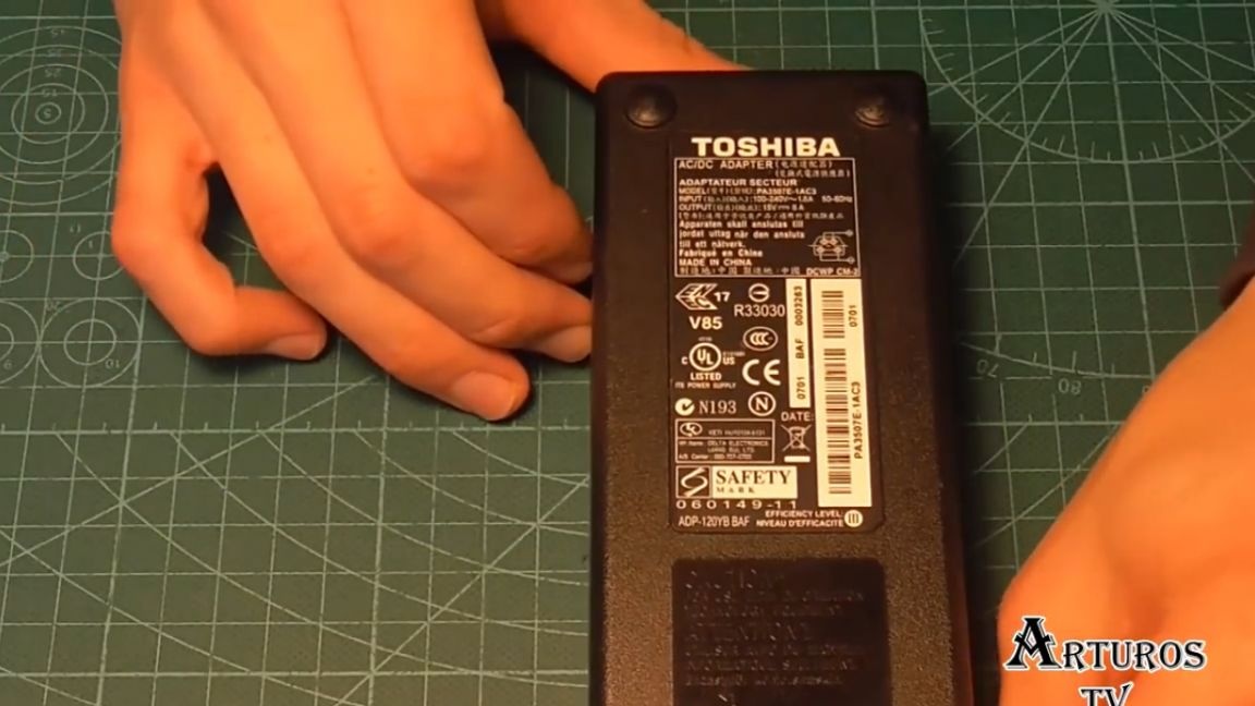
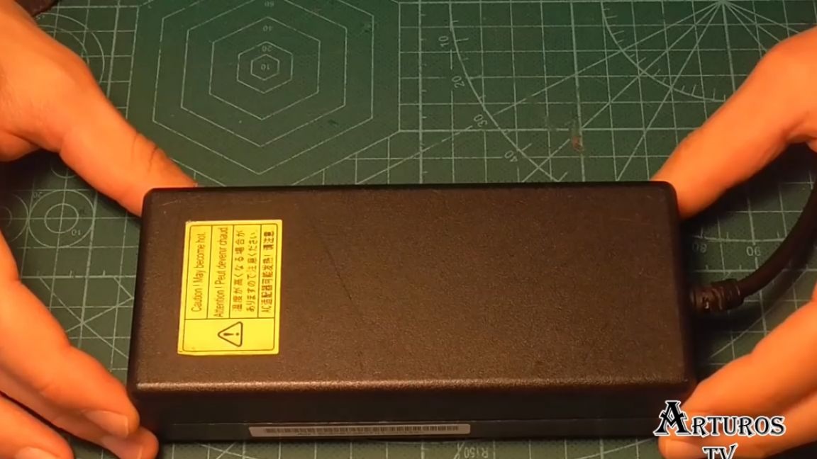
So let's get started. The author will use a power supply from a laptop, which produces a voltage of 15V and a current of up to 8A. That will be quite enough.
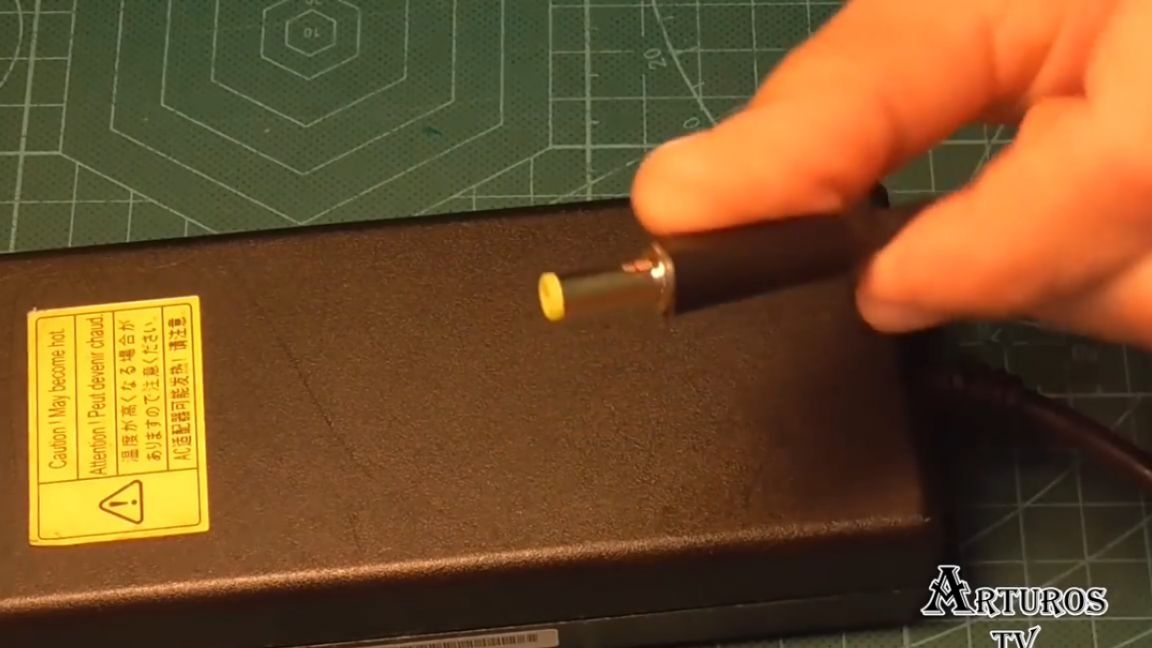
He soldered a suitable connector to the power supply cord, with which he would connect the power supply to a step-down circuit.
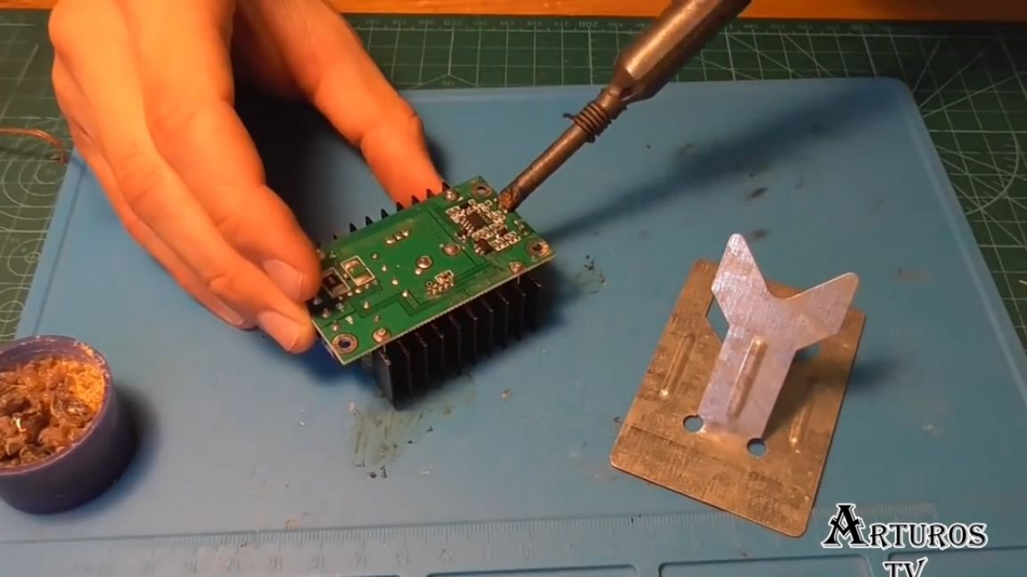
As a step-down converter, a fairly widespread module was selected, on which both voltage and current can be changed using these two potentiometers.
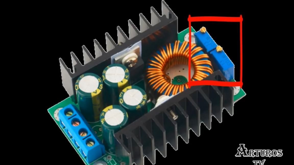
However, the author considered such potentiometers not very convenient and therefore decided to replace them with others, since most likely a very precise voltage adjustment would be required. It was decided to take a multi-turn potentiometer in order to further facilitate the task.
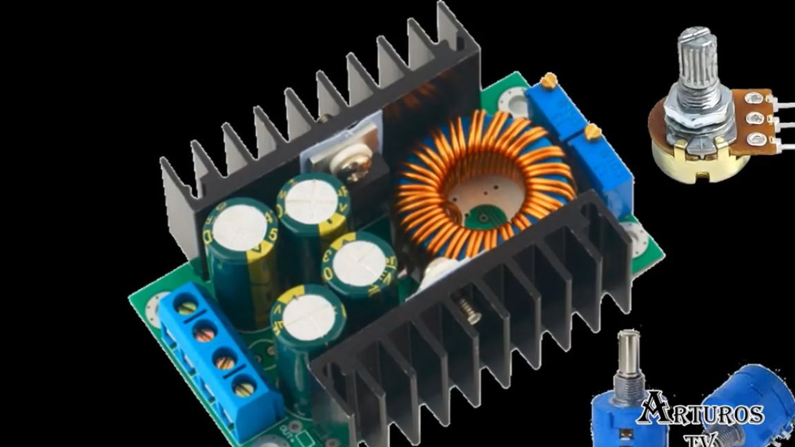
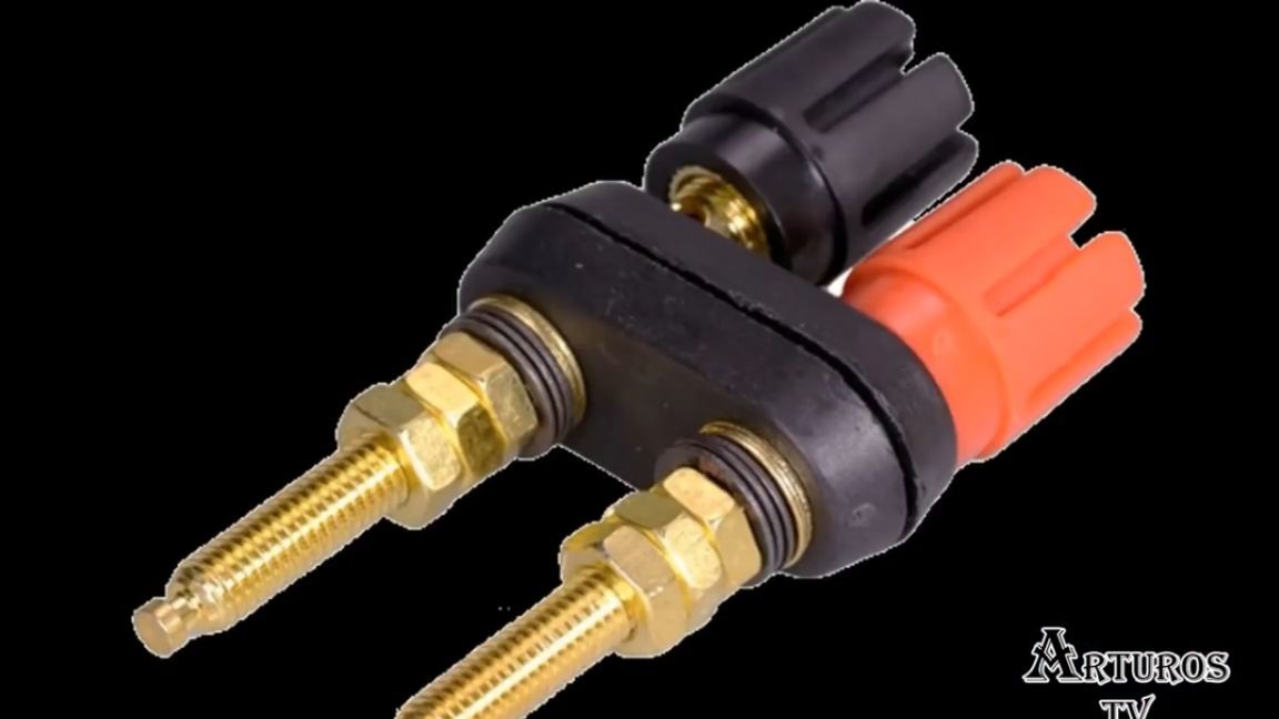
We will adjust the current with a conventional potentiometer, since there is no need for greater accuracy. But basically, you decide which potentiometers to use. Further, a very important component is a multimeter with a display on which values will be displayed. To connect various kinds of loads, banana plugs were selected.
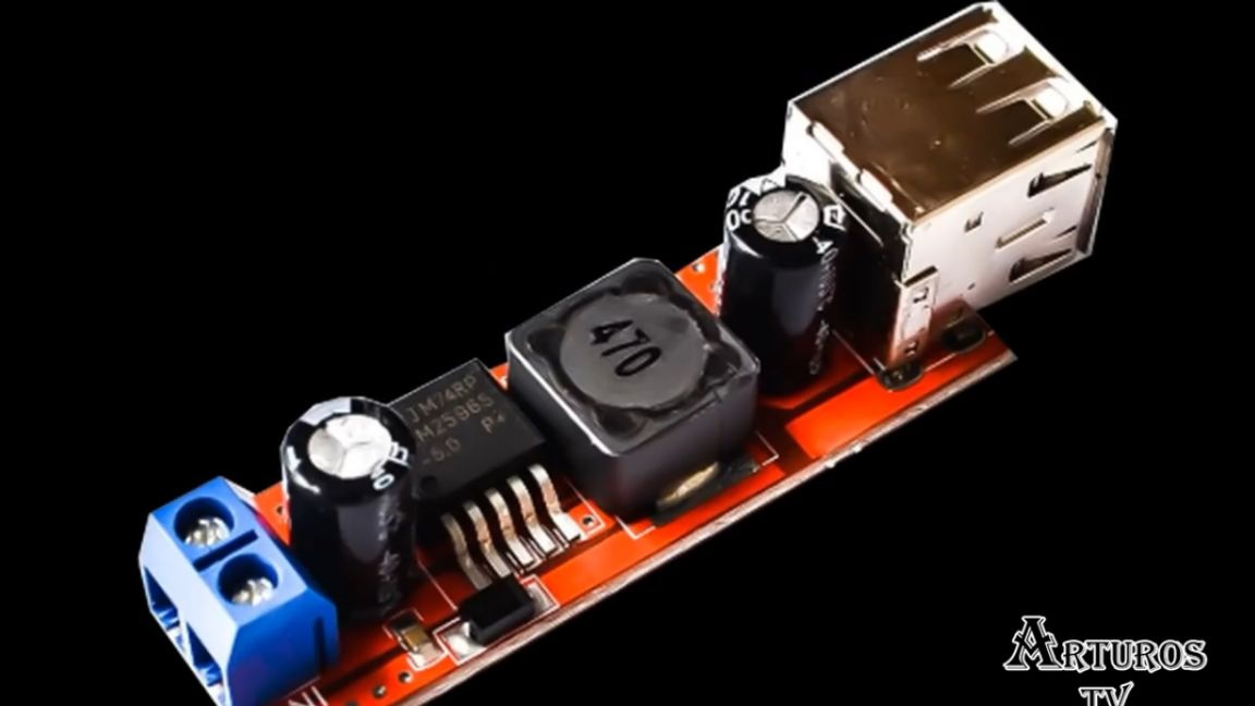
It was also decided that taking 5V from the USB port is also quite convenient, because this way you can power, for example, arduino. So let's add another module.
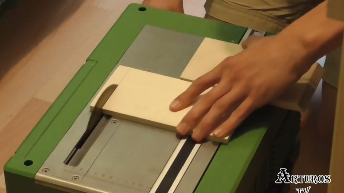
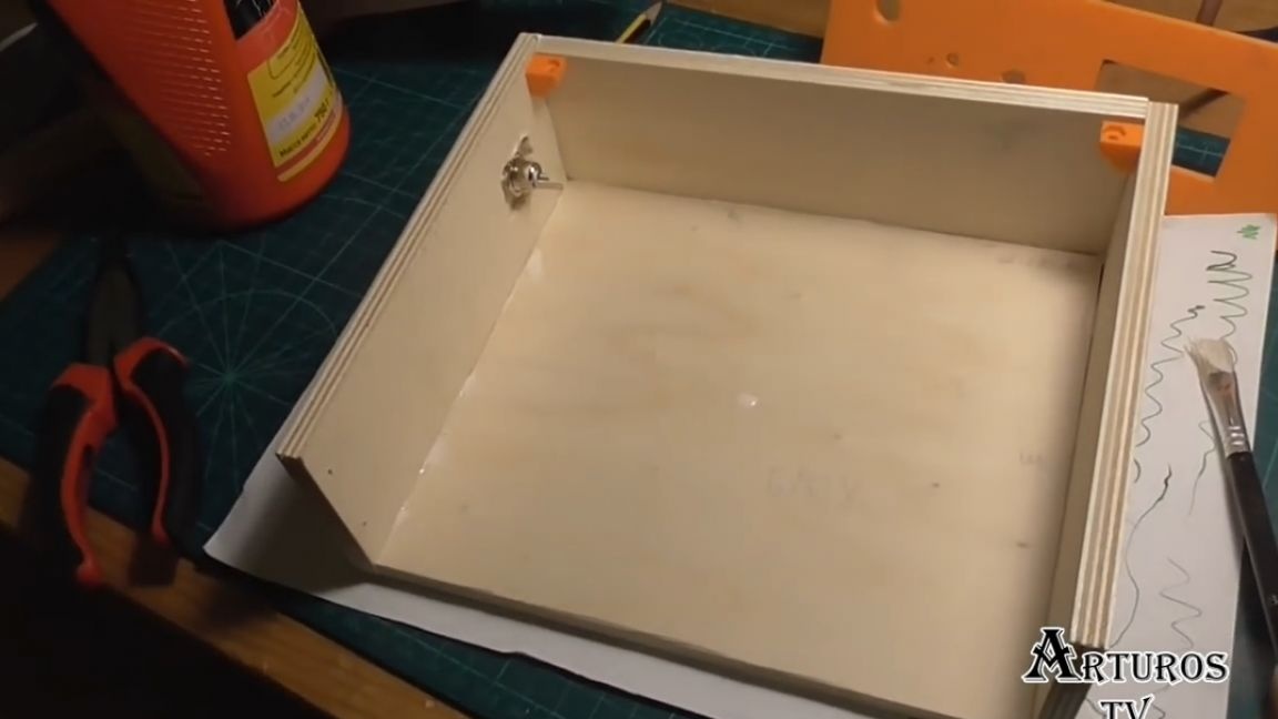
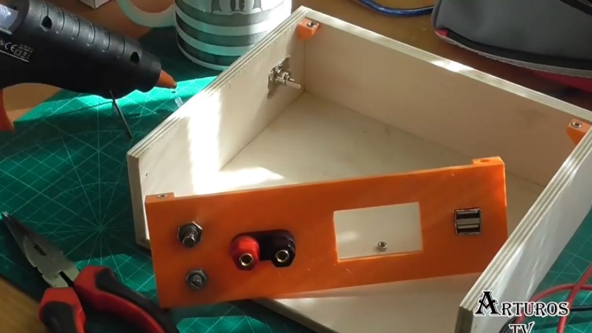
Well, we figured out the components, now let's get to work. The body will be made of plywood 8 mm thick.

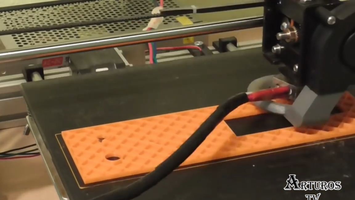
And since the author has a 3d printer, he could not resist and used it in this project to print the front panel. The 3d printer was also used because most of the holes on the front panel are of an absolutely non-standard size, and it’s almost impossible to find drills of the correct diameter, and I don’t feel like working with a file without end.
Next is woodworking.It is better to use a circular saw (of course, if you have one), and you can also use a jigsaw.

The front panel printed for about an hour and a half.
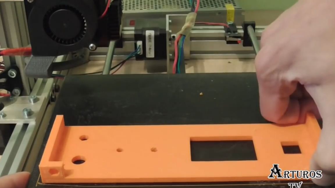
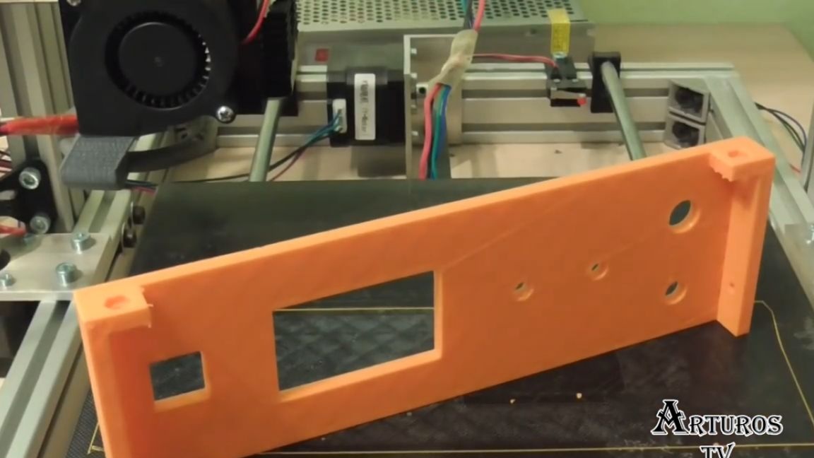
As a result, most of the holes turned out to be just in size, but unfortunately the distance between the holes for the banana plugs was not accurate and the author had to work a bit with a drill. Next, you need to glue the case.
Well, while the glue is drying, let's look at the diagram:
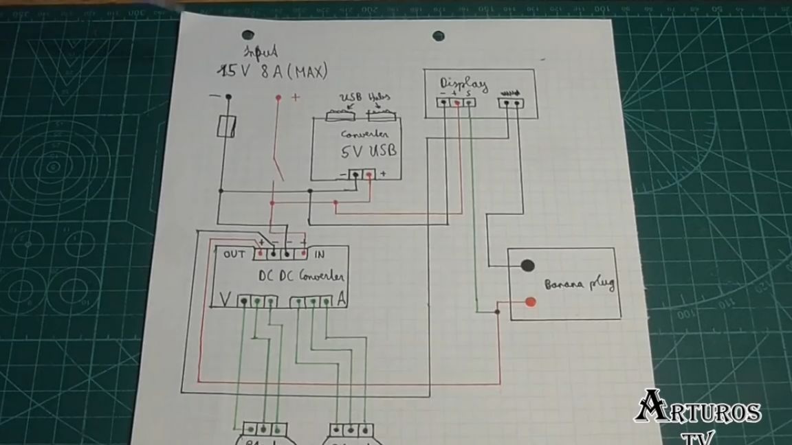
So, at the input we get 15V. There is a switch with which we turn the circuit on and off, and when it is closed, the module with the USB port is immediately powered. It has a step-down converter, so it is powered directly. The author also added a fuse. As soon as the switch closes, the display with a multimeter is also powered. Further, the main part is the main converter.
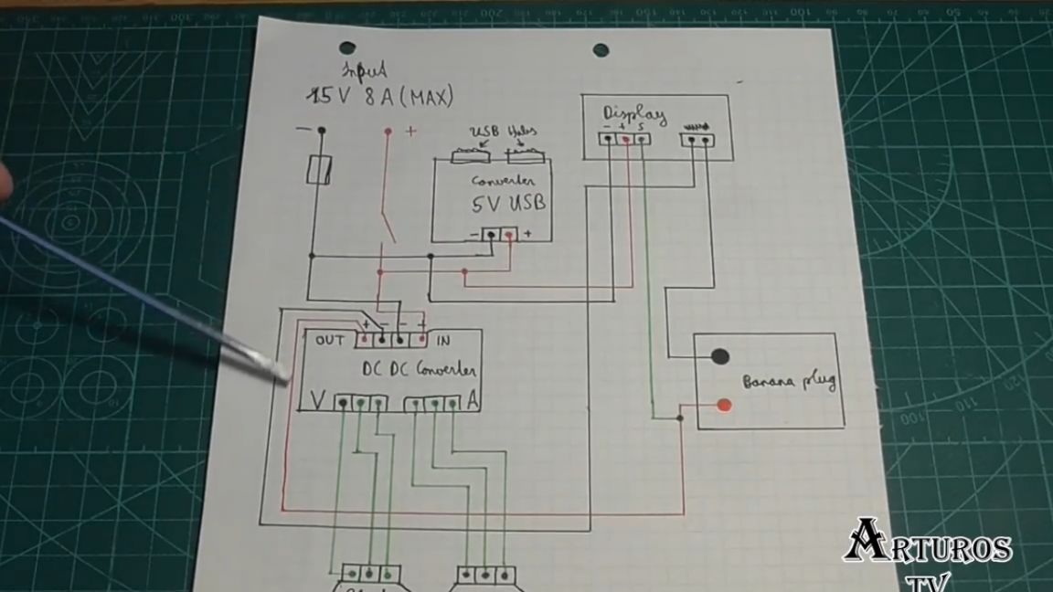
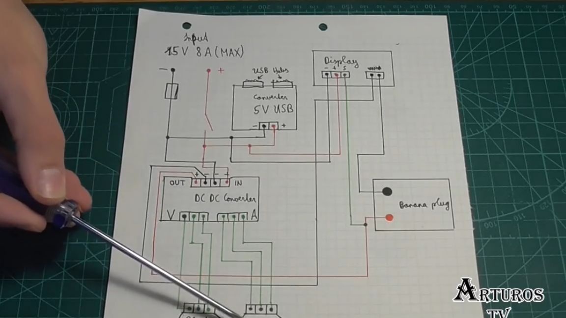
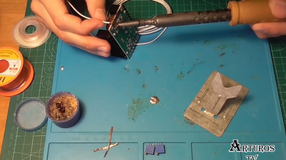
Here, of course, we have 2 potentiometers, the negative contact from the converter is connected to the display as if to open the circuit, and then goes to the negative contact of the banana plug. In this way we can measure current. But the positive contact from the converter goes directly to the contact of the banana plug, and in parallel to it is connected the contact from the multimeter. So we measure the voltage. And in general, everything, you see, is very simple. First, we solder the native potentiometers.
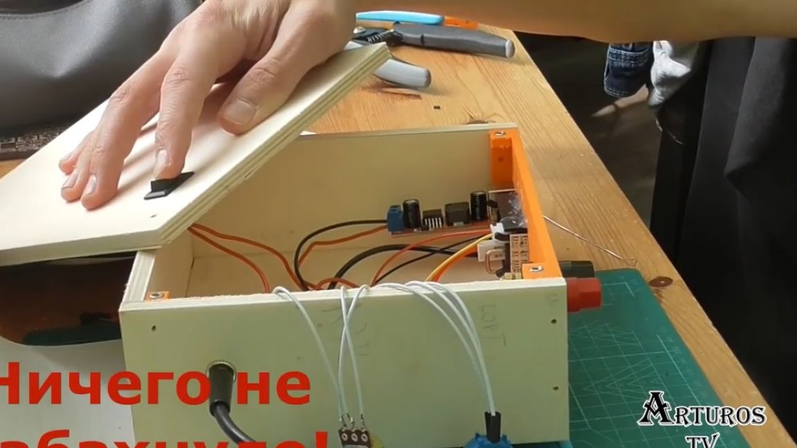
Well, now we just collect everything according to the scheme.
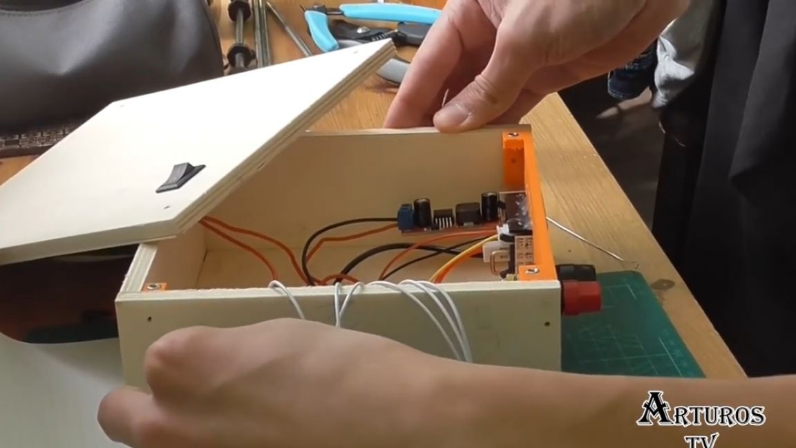
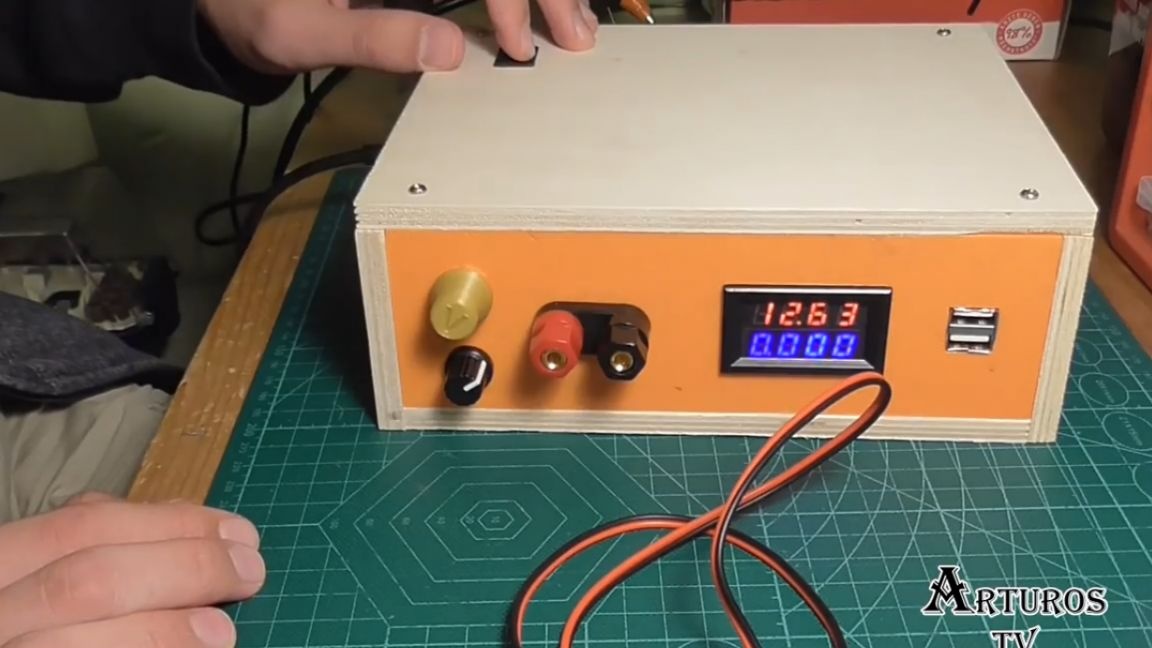
So, everything is assembled, the first test.
For the first test, the author decided to connect the motor.
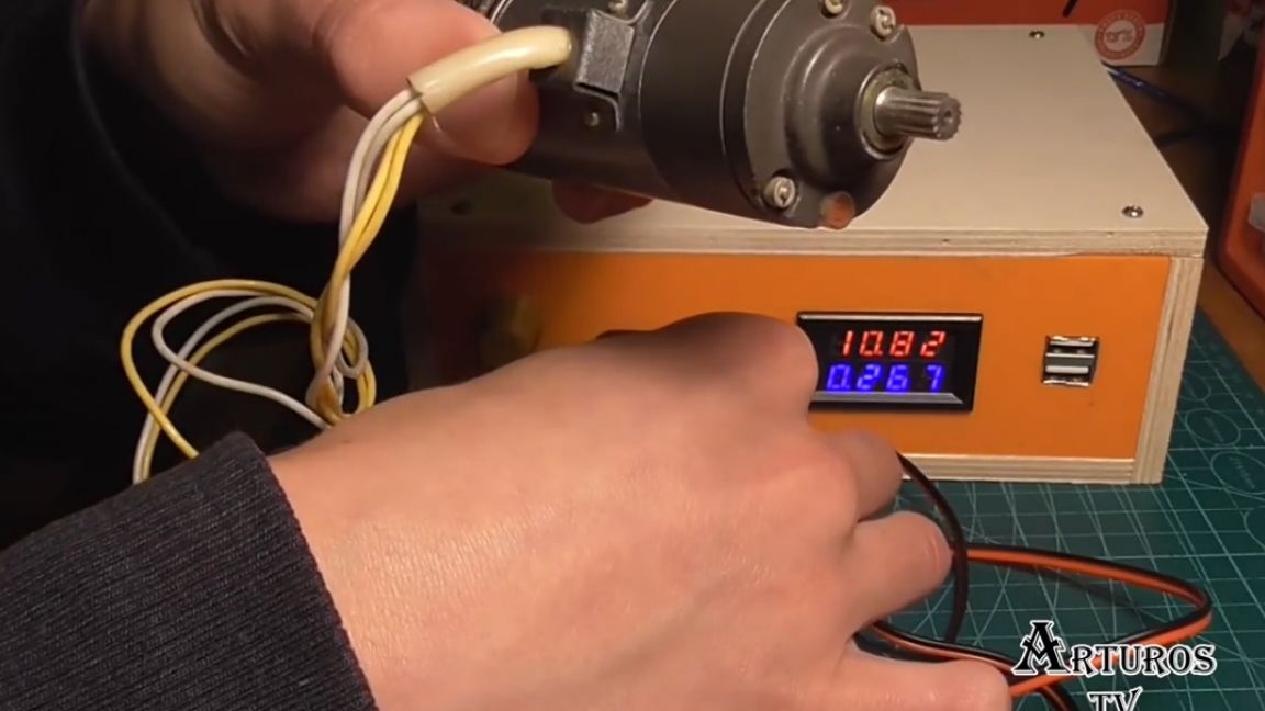
As you can see, everything worked very well. We also see that the multimeter indicates what current the motor consumes.
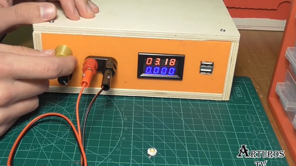
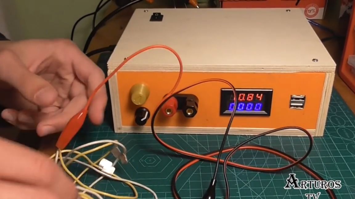
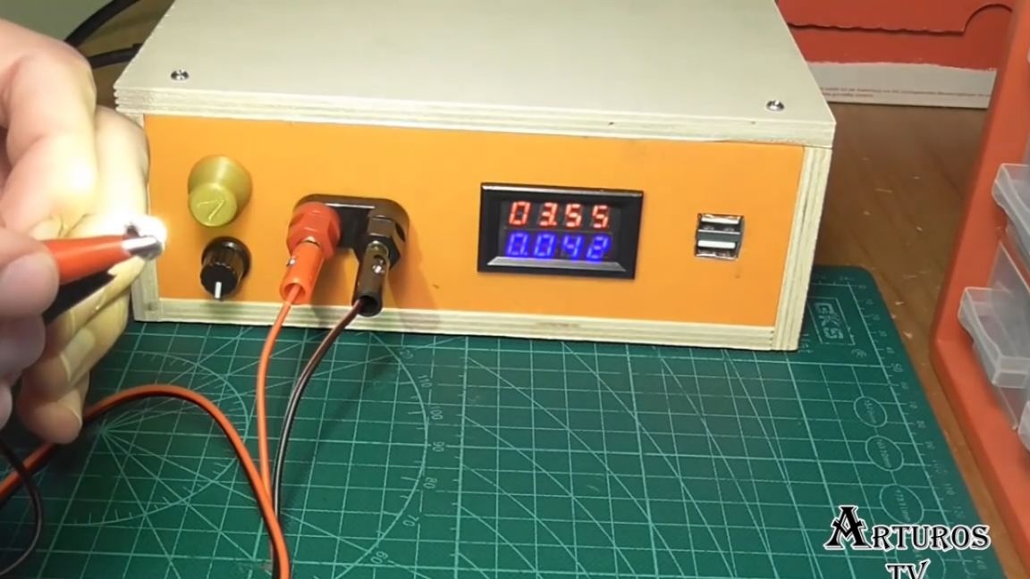
Setting the voltage also works fine, but one of the features of this dc-dc converter is the ability to set the current as well. To do this, we need to short-circuit the plus and minus.
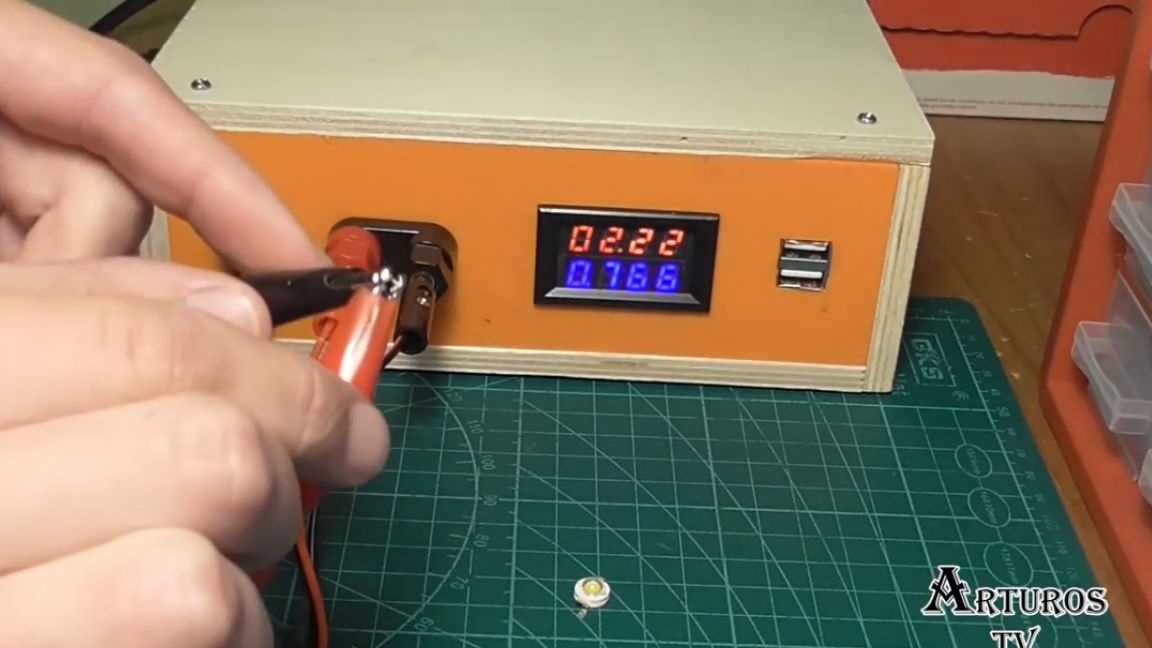
After that, we can adjust the current using the lower potentiometer.
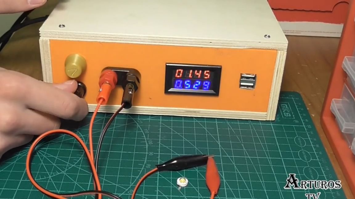
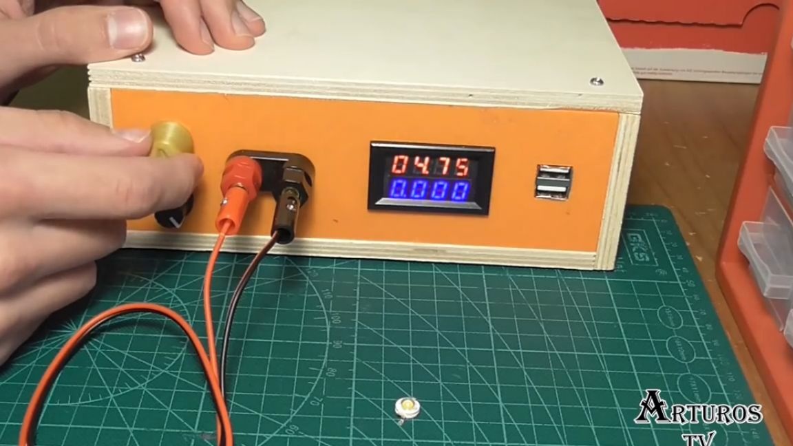
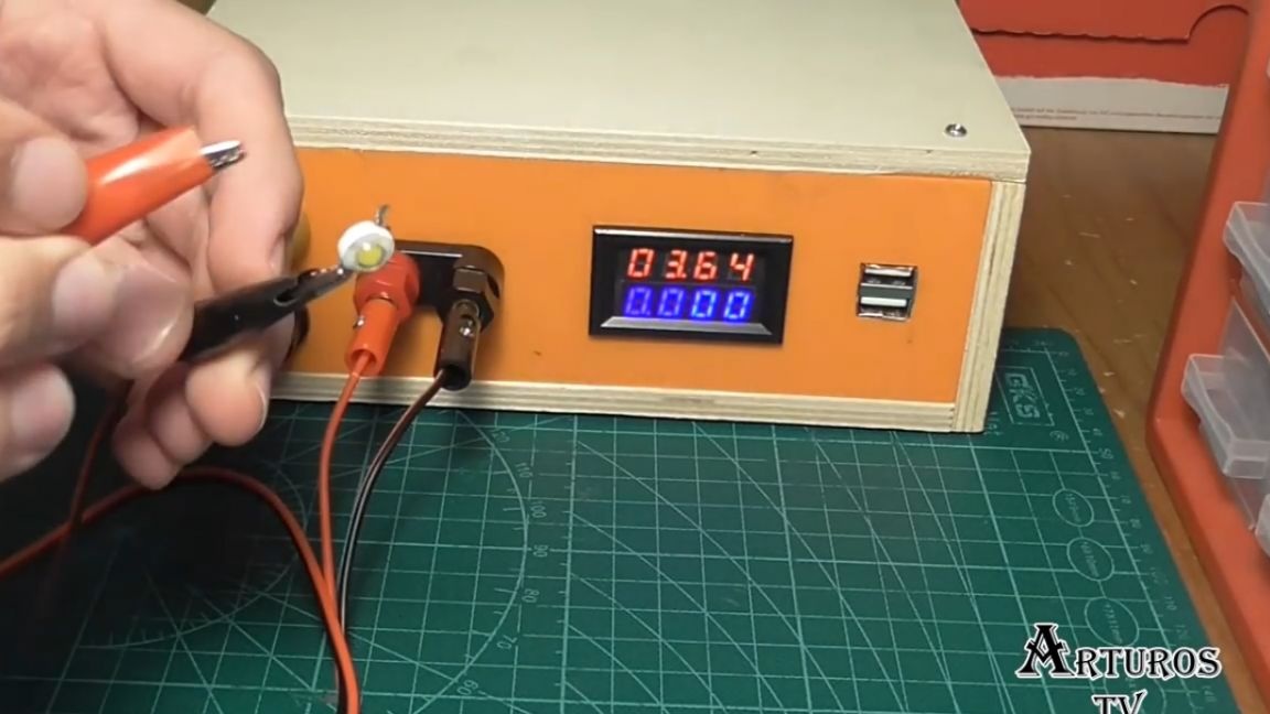
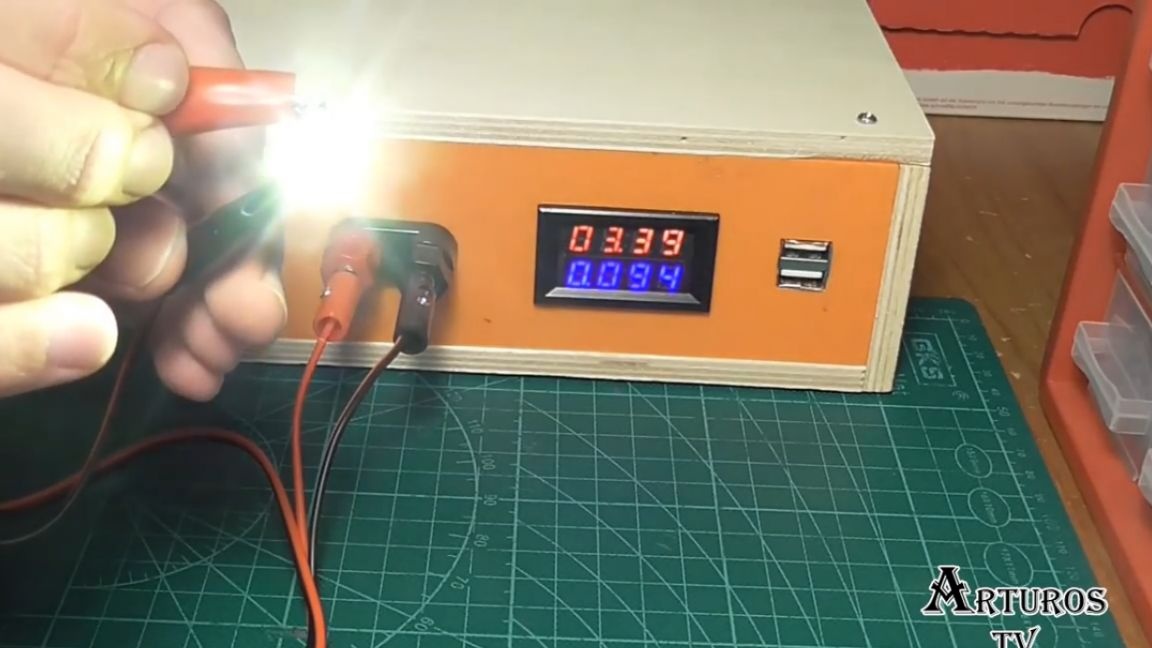
This is a very useful function if we want to, for example, charge the batteries or test a powerful LED.
Well, that’s probably all. Thank you for attention. See you soon!
Video: