

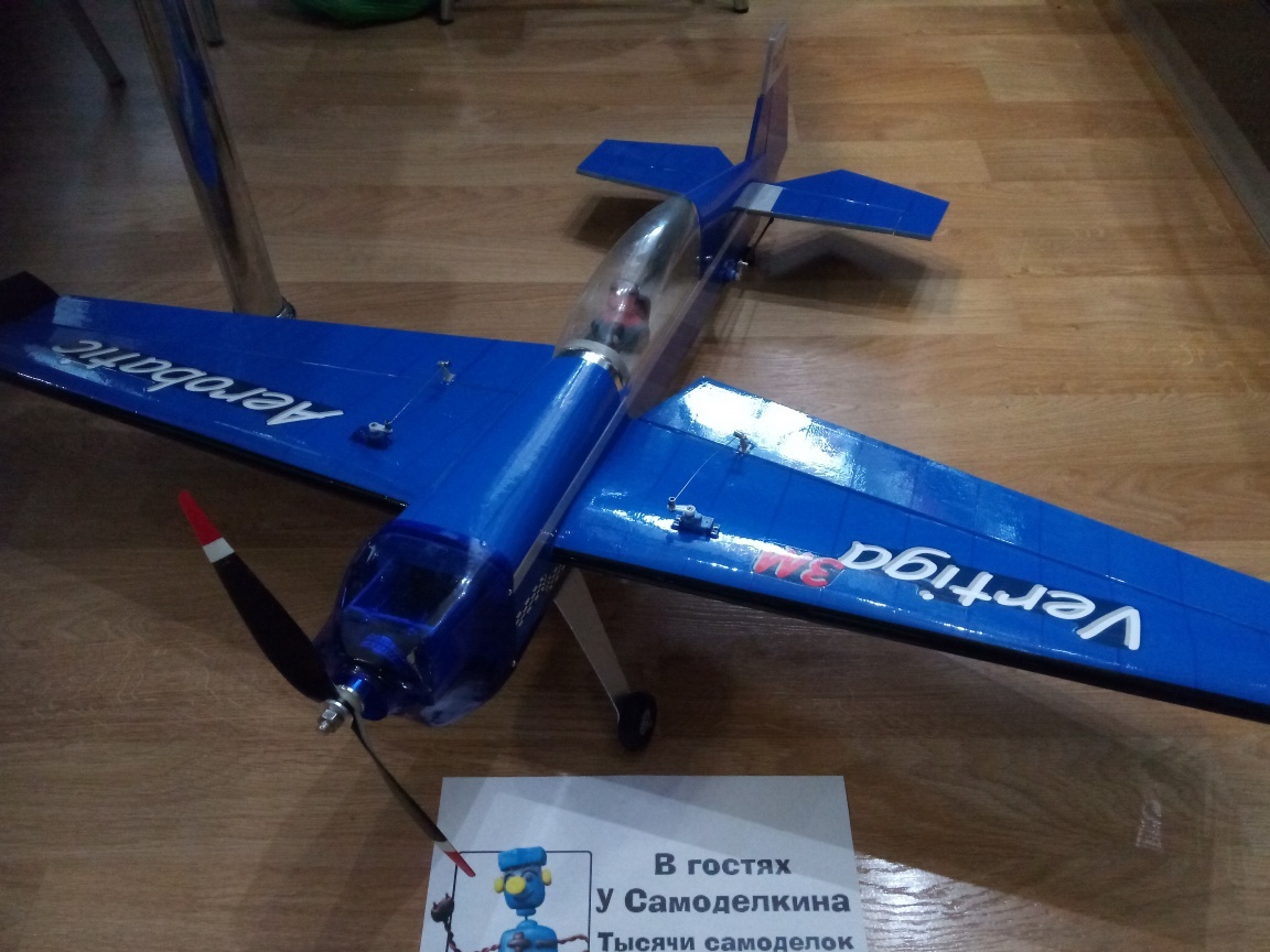
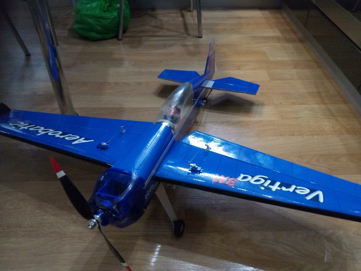
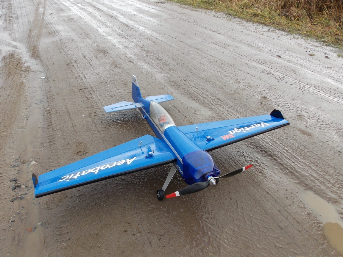
This article will be a detailed description of the construction of the aerobatic model of the Czech aircraft Vertiga 3M. This model very well established in the sky, durable (which is good for novice pilots) and made of the most affordable materials.
Materials:
- Laminate flooring
- Bamboo flooring slats
- Plastic bottles
- Plywood
- Dural tube
- Sheet duralumin
- Bamboo skewers
- Glues (PVA, epoxy and ceiling)
- Scotch tape in different colors
- Serpyanka
- Bolts and nuts
- steel wire
- Pieces of thin transparent plastic
- A4 paper
Instruments:
- Cutter
- Jigsaw
- Sandpaper
- pliers
- Markers
- Ruler
- scissors
- Thermogun
- awl
- Needle files
- Vise
- Screwdriver and drill
- Construction hair dryer
- Hacksaw for metal or jigsaw
- Dremel
Electronics:
Motor - Turnigy D3530 / 14 1100KV
Servos - Turnigy TG9e, 9g / 1.5kg / 0.10sec
Speed controller - Hobby King 30A with 3A onboard power supply stabilizer (UBEC)
Propeller - 12x6 inches
Batteries - 2200 mAh 3S 25C
Equipment - any on 4 channels and more
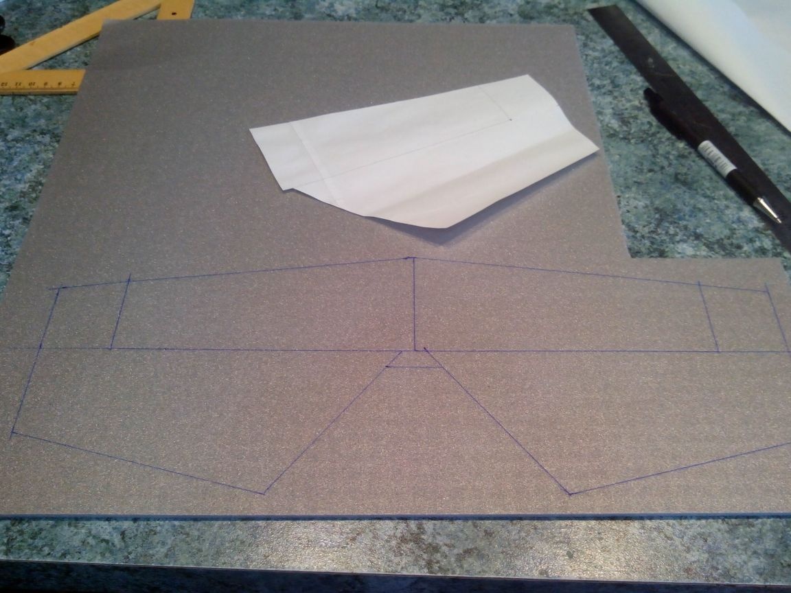
Step 1. Drawings.
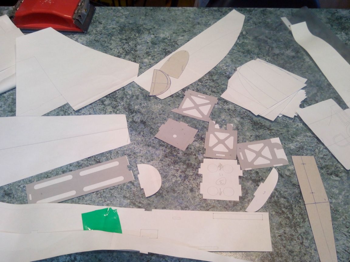
We print them, glue the A4 sheets and cut out the parts templates.
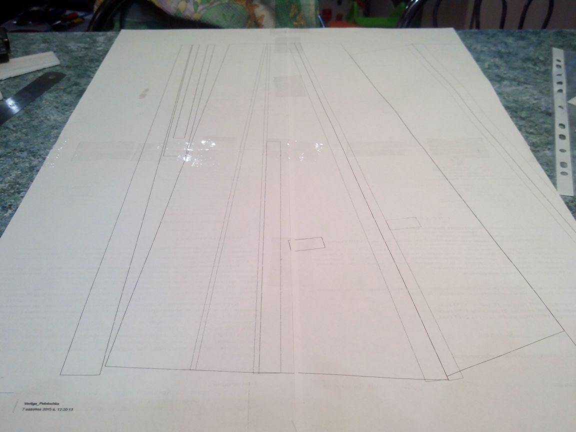
Since the field tests of the model showed the most fragile places, it was decided to make some changes in the design in order to increase strength.
The archive drawings in CDR and PDF.
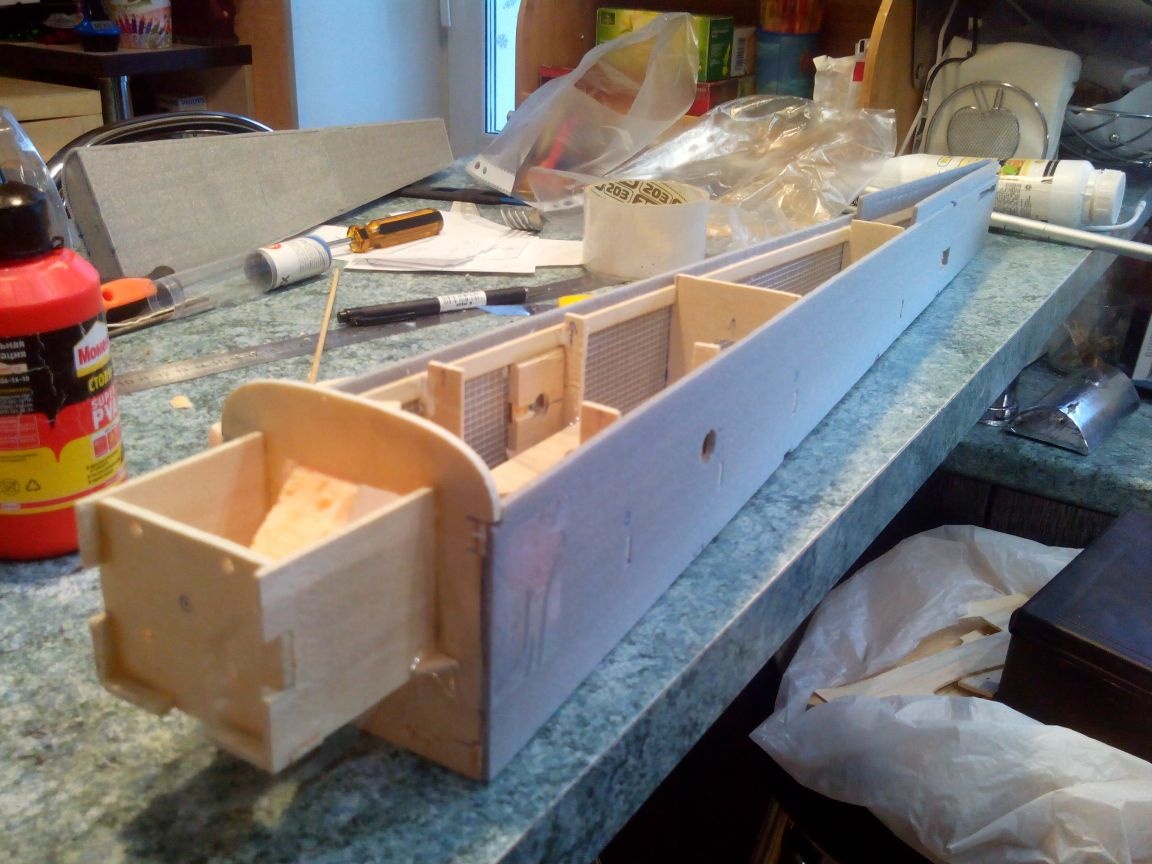
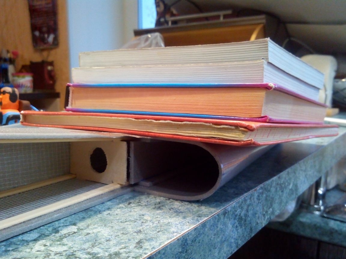
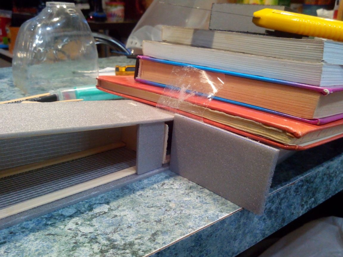
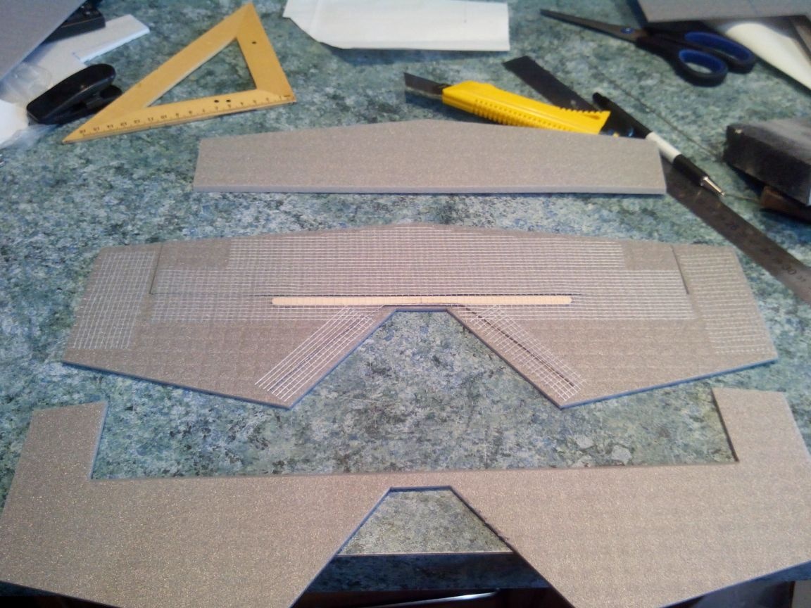
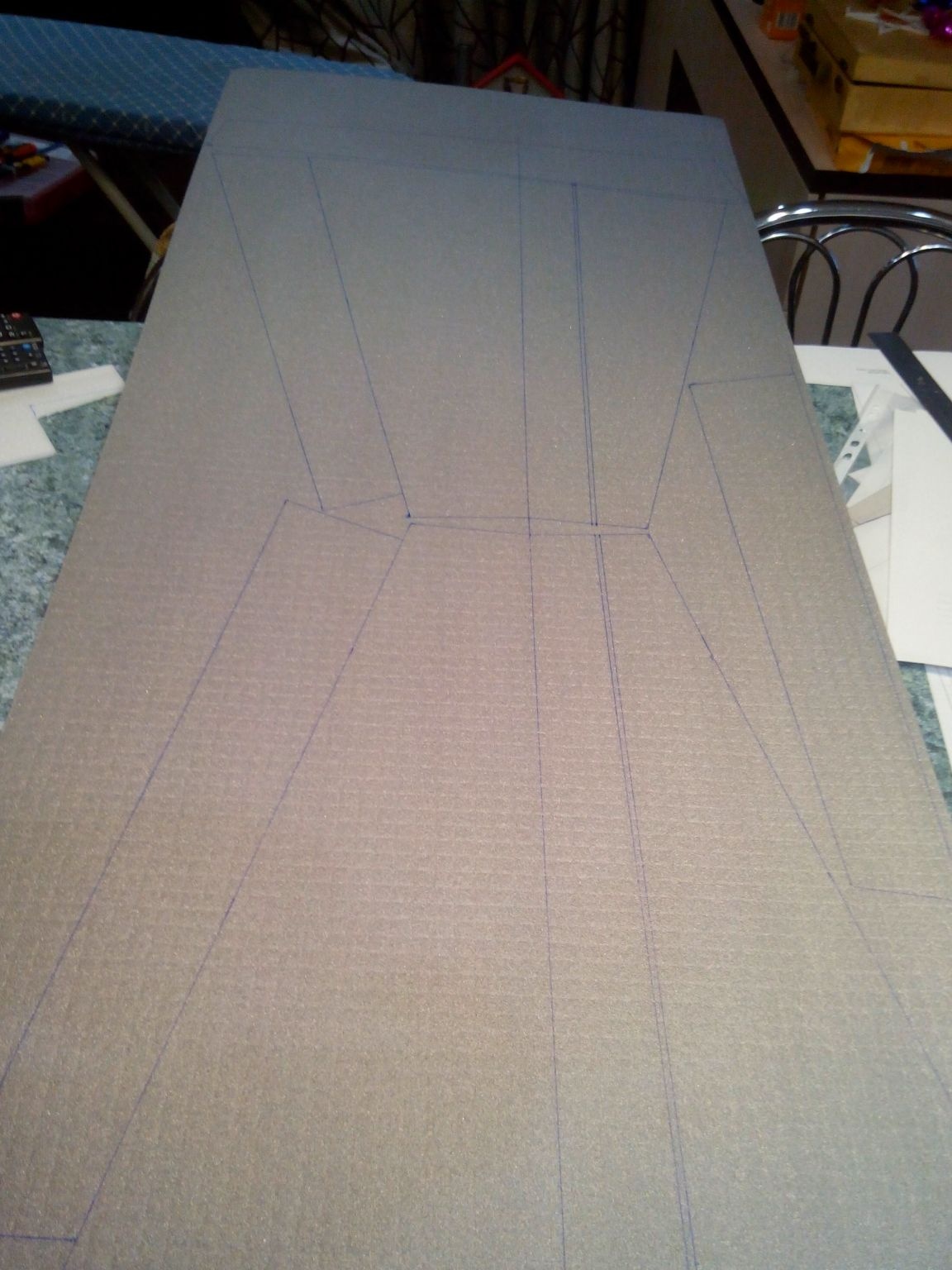
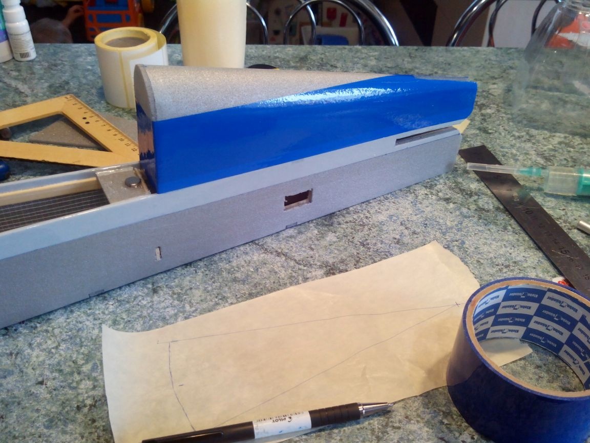
Step 2. Making the fuselage.
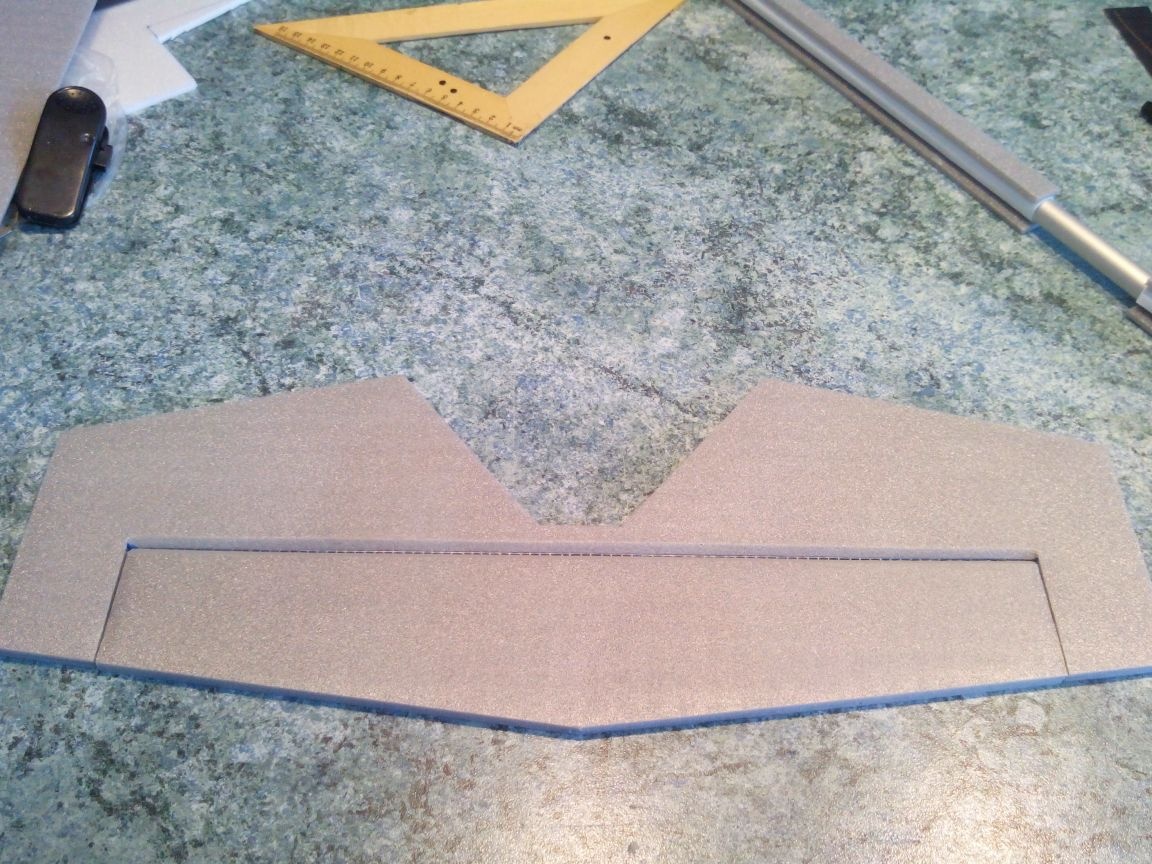
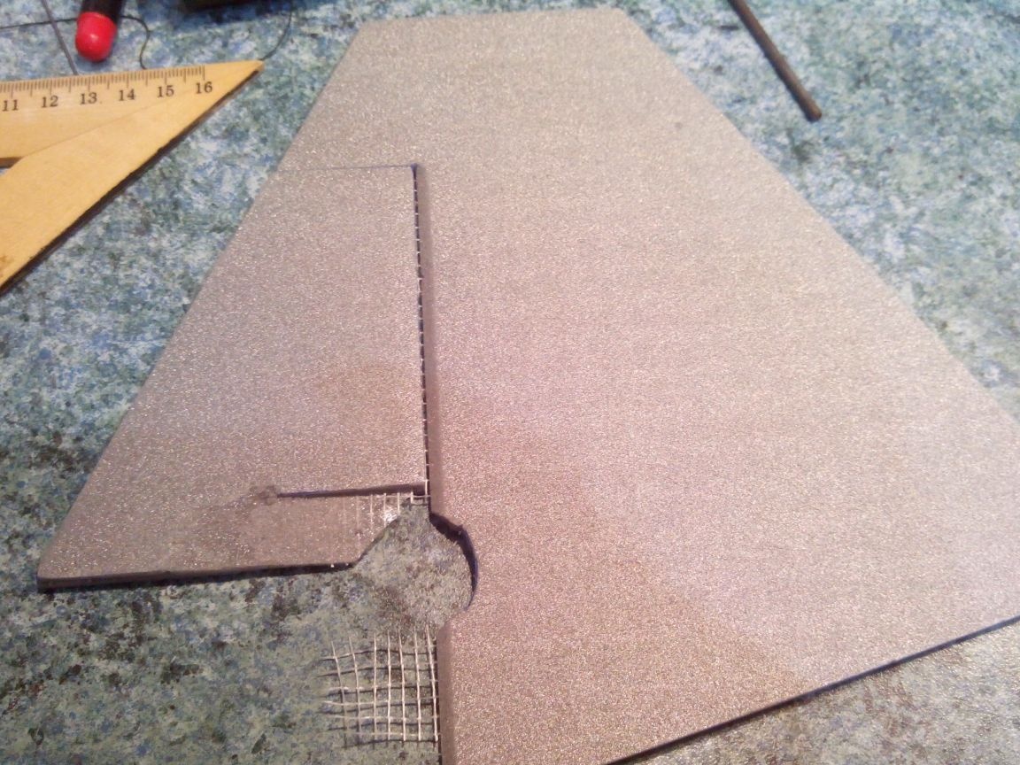
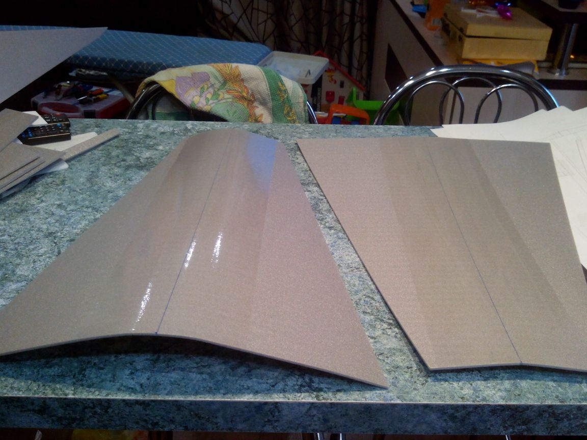
Using the templates, we transfer the fuselage details to the depron.
Cut them with a cutter and make cutouts for frames.
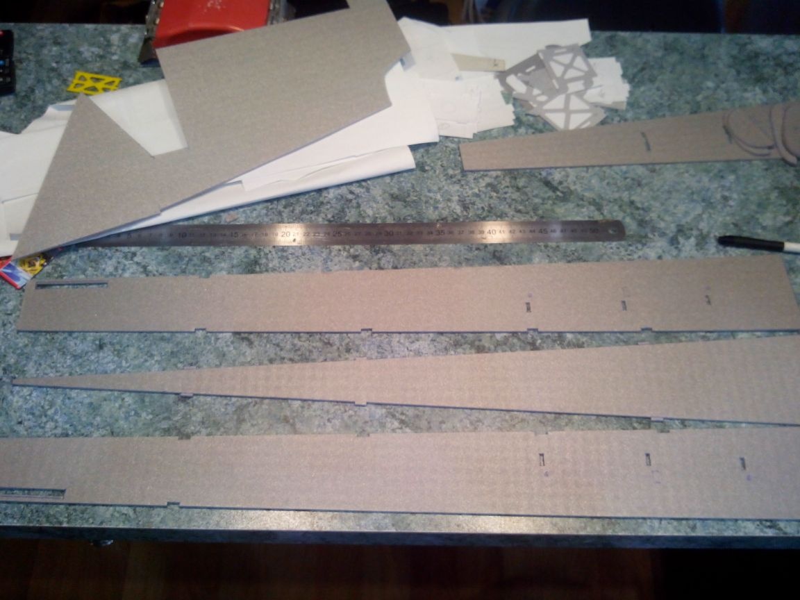
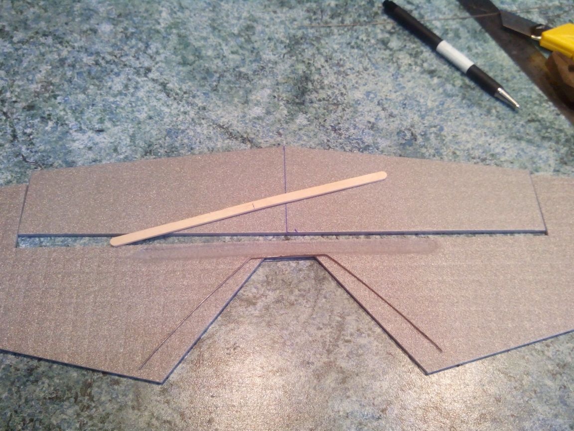
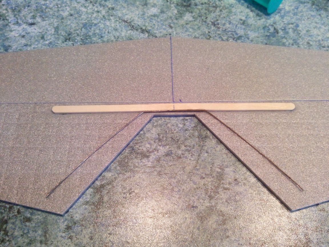
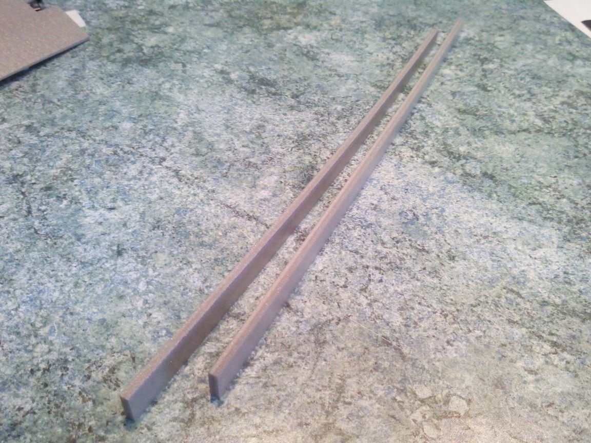
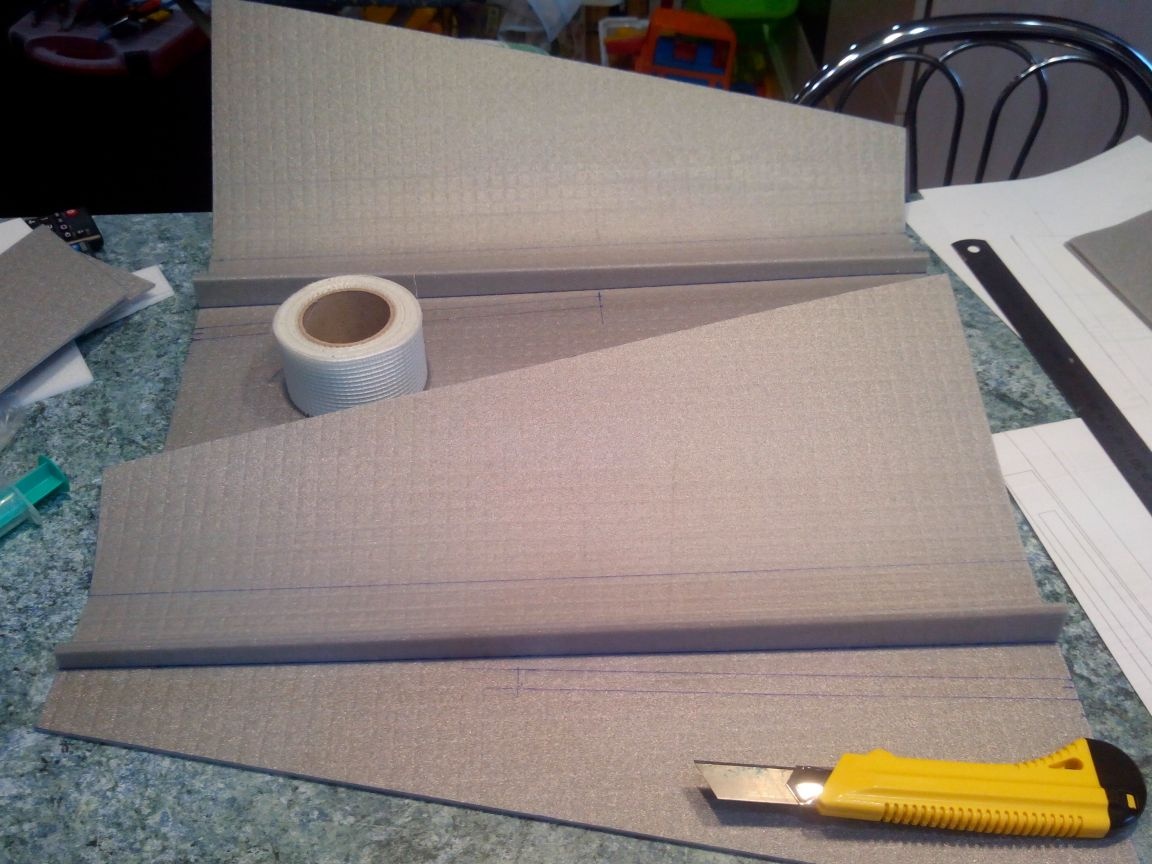
We glue the battens from the bamboo mat with ceiling glue on the sides of the fuselage (or use regular battens with a section of 2x8 mm). In the drawing, the rails go only to the gargot, but with a rough landing the fuselage breaks in this place, therefore it is better to let the rails run along the entire length.
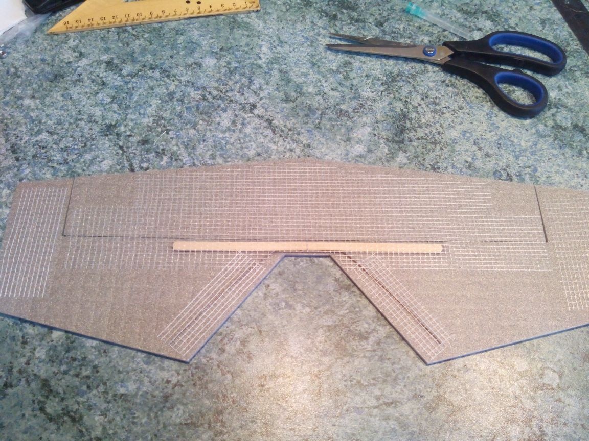
In addition, in order to strengthen the walls, we glue the sickle along the entire length from the inside and coat it with ceiling glue.
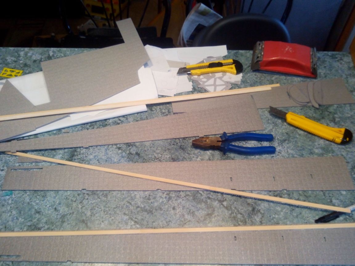
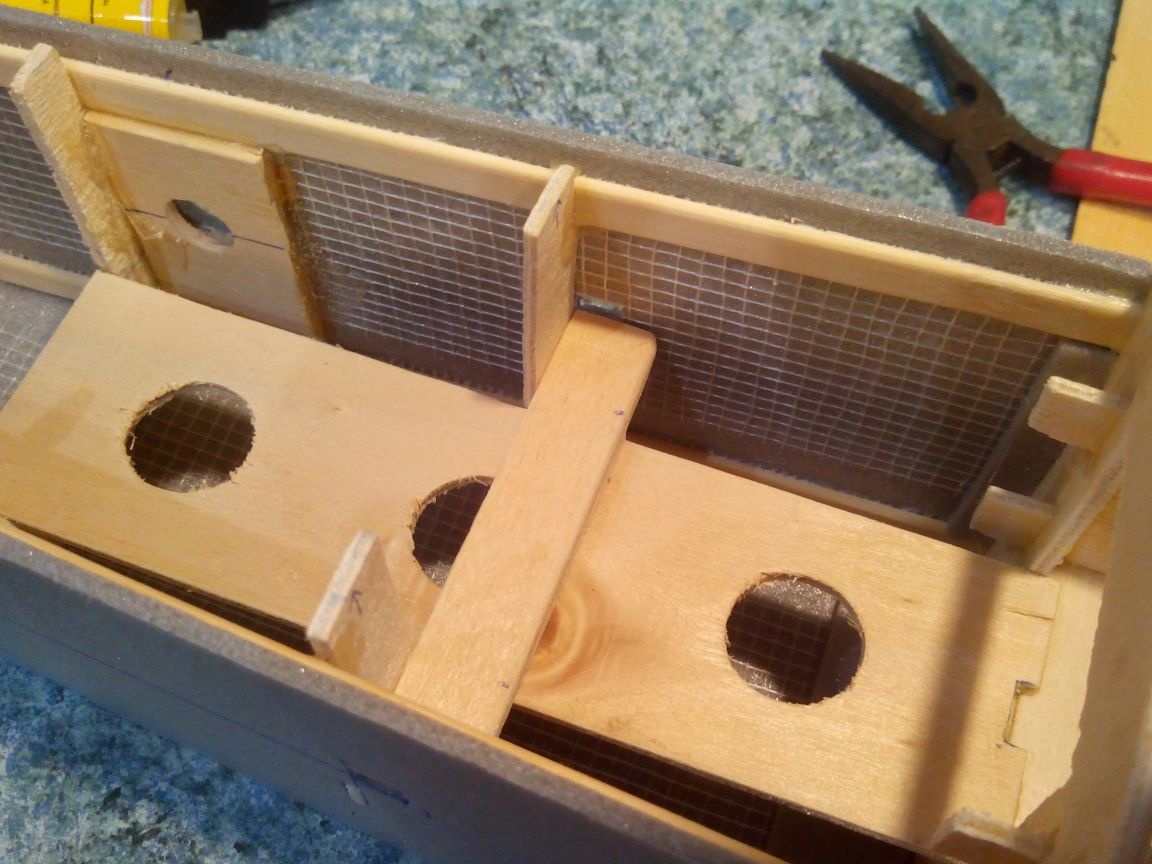
From plywood, we cut out the frames for tail feather servos with a jigsaw.
Glue the frames from the inside to the sides of the fuselage.
In the rear part to the sides of the fuselage, we also glue the strips from the inside from the inside - to strengthen the space under the stabilizer and to seal the gargot.
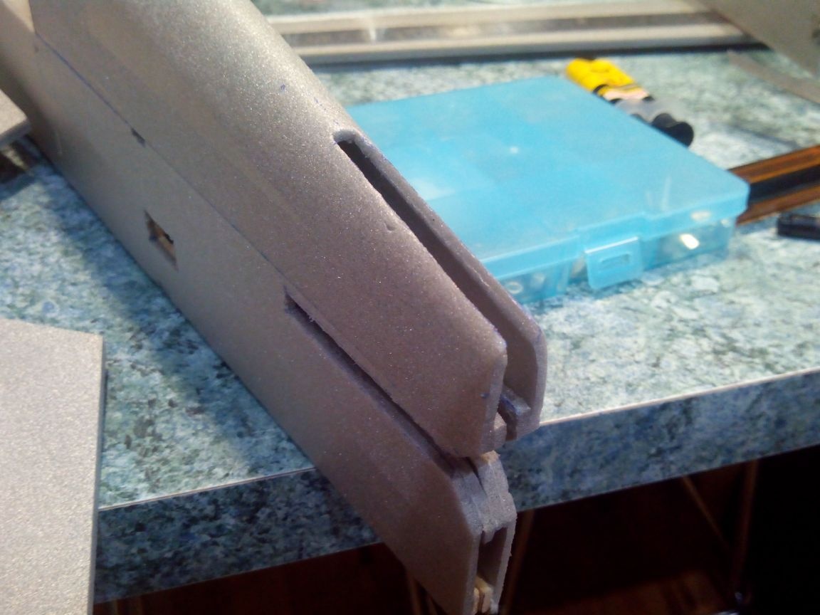
Glue the second rails to the sides of the fuselage.
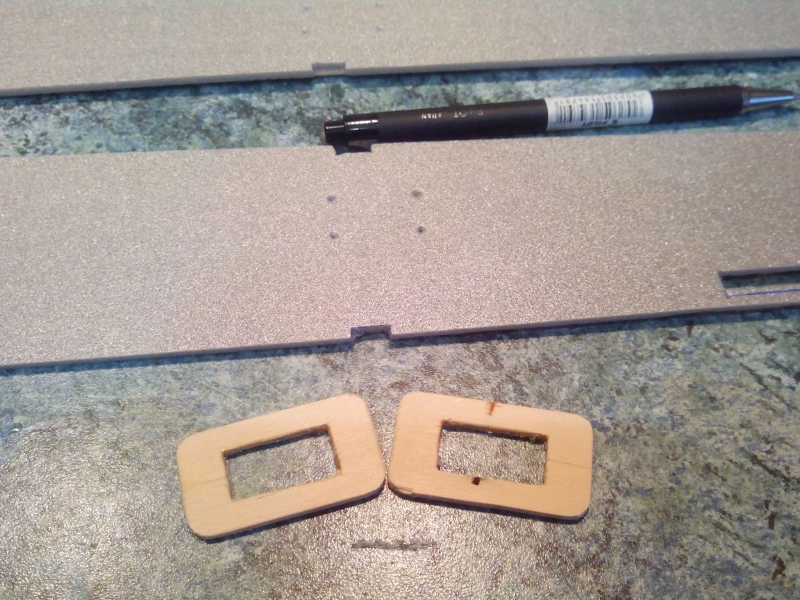
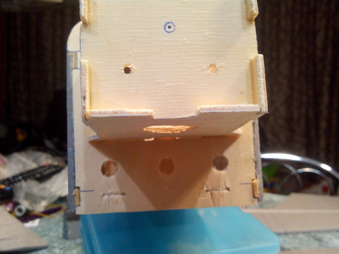
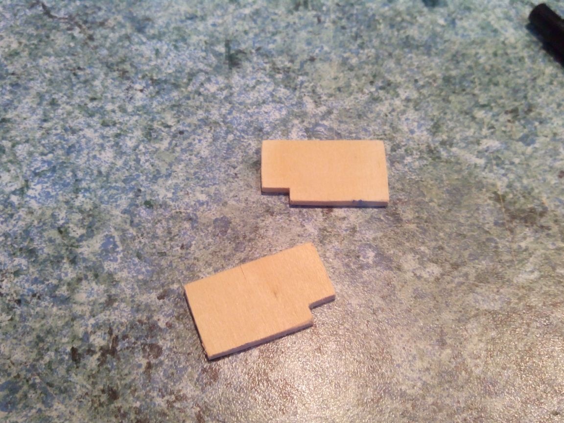
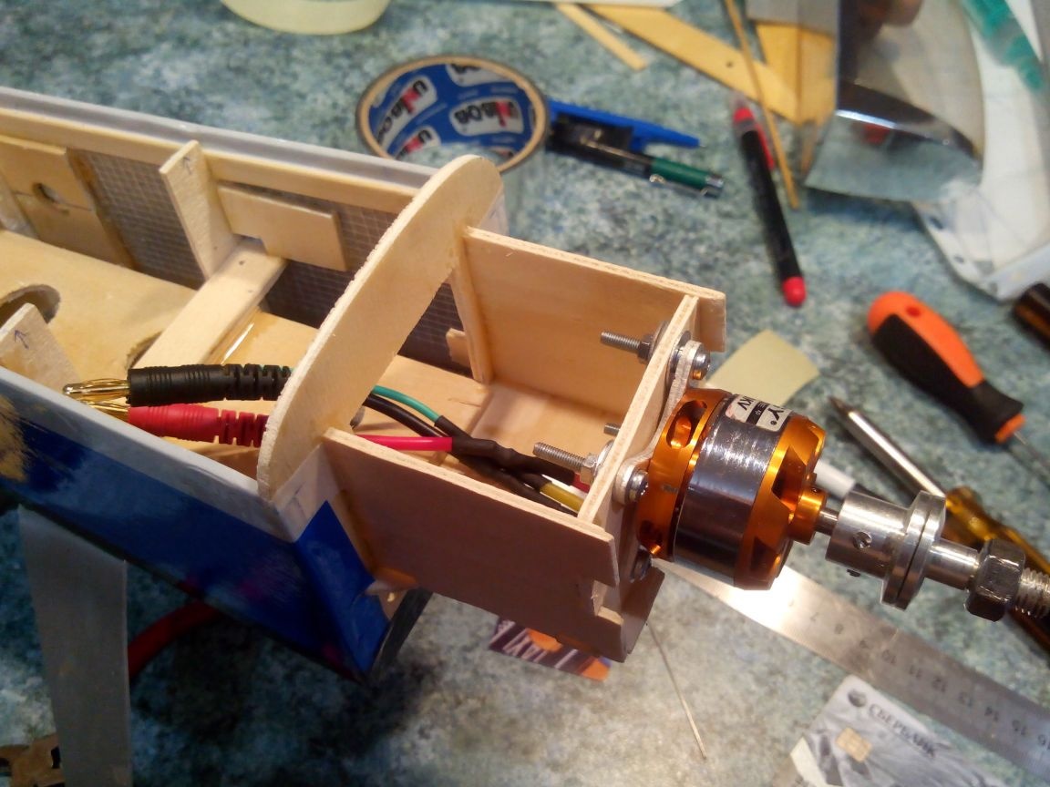
On plywood from boxes according to templates we draw details of engine mounts.
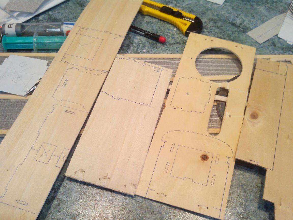
We cut out all the details and process the edges with sandpaper.
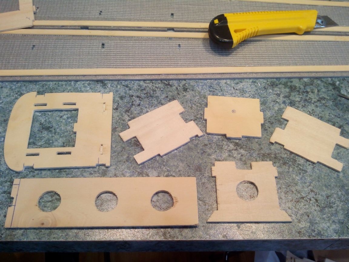
We glue motor mount with PVA glue.
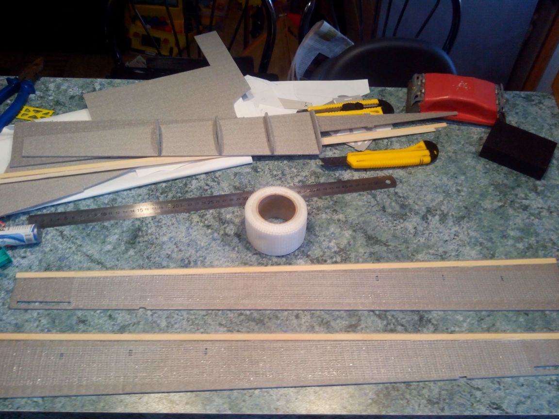
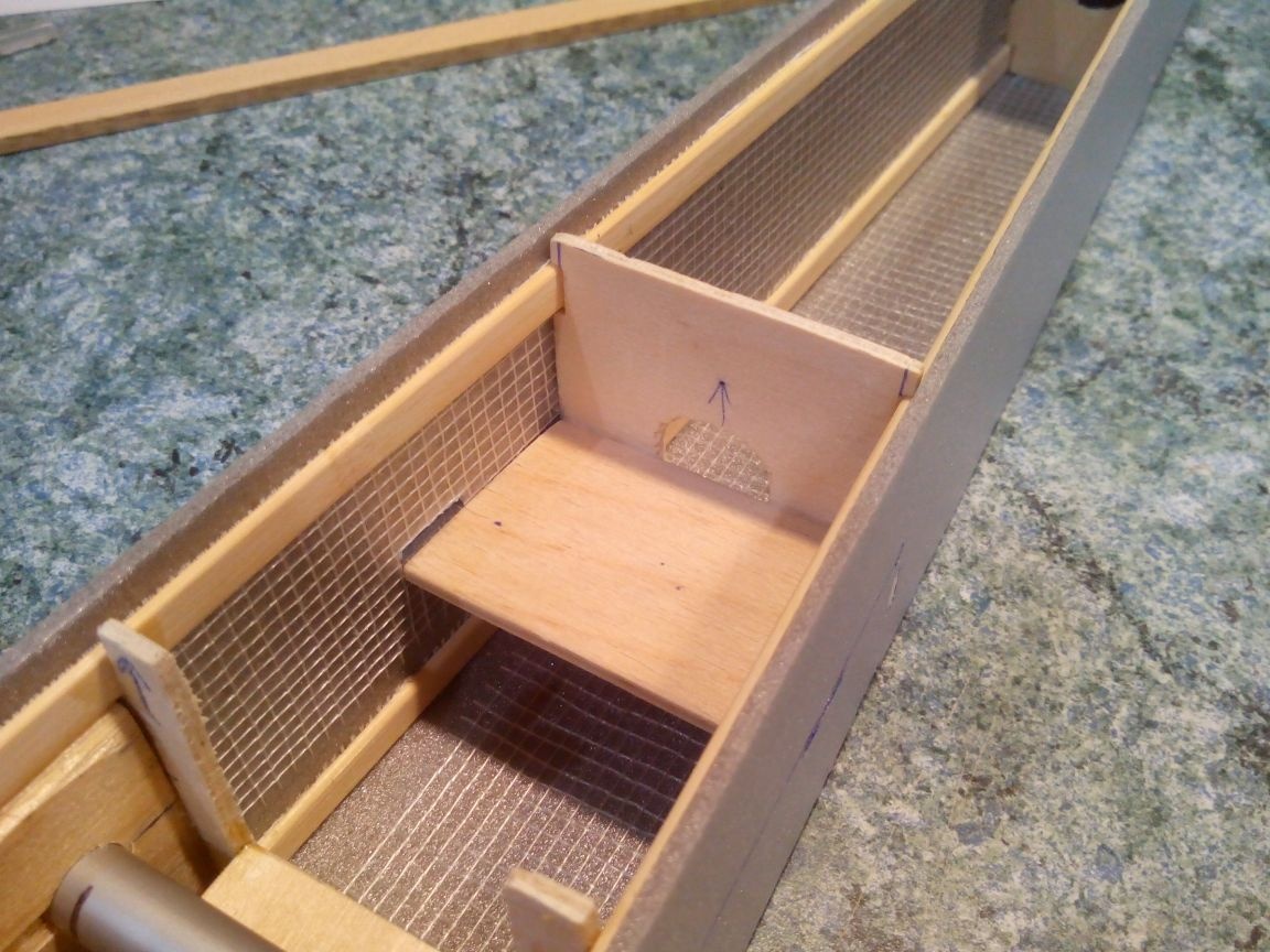
We cut out all the frames from the same plywood (in this case it was decided to abandon the depron so that the model was stronger).
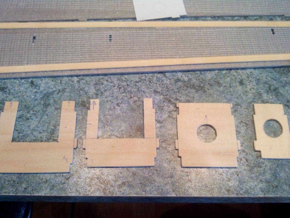
We attach plywood reinforcements for the side member (tube) to the sides of the fuselage.
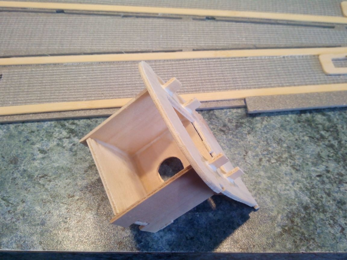
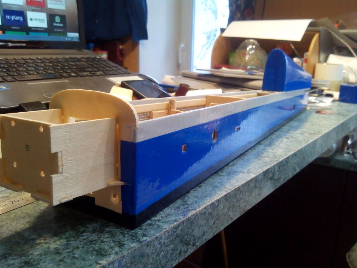
We glue the sides of the fuselage to the engine mount and glue the frames.
We reinforce the bottom of the fuselage with a streak of sickle, glue it and try on the spar tube.
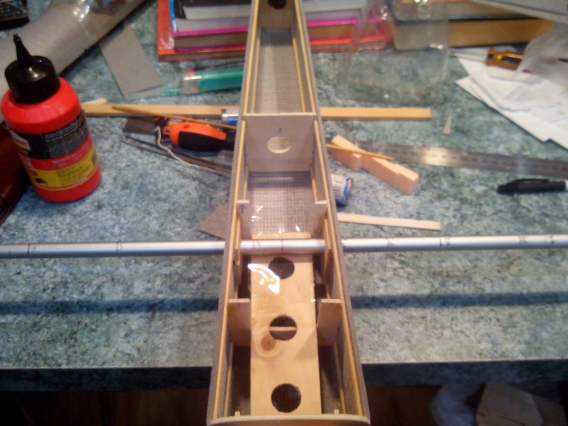
In the engine mount below we make ventilation holes.
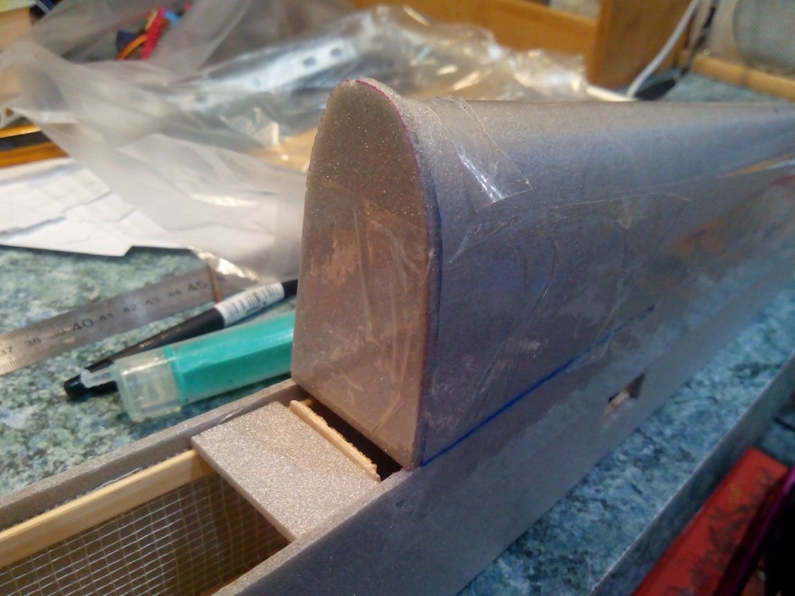
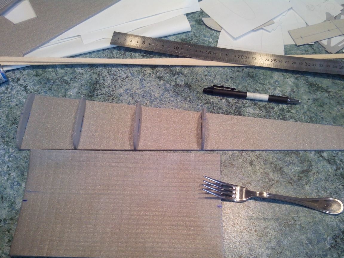
Before gluing the gargot, be sure to glue the part on the outside with tape and push the strips with a fork from the inside, otherwise the depron will break when bent.
We seal the gargot with ceiling glue and fix it with tape.
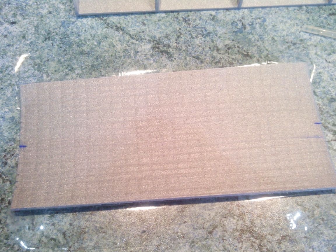
Then put under the press and leave until the glue completely dries under the press.
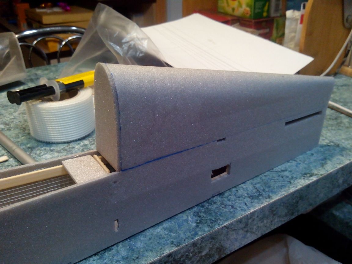
We seal the gargot in the front and glue a small area under the magnet that will hold the lid.
After the glue dries, we cut off the excess with a cutter.
We remove the entire tape and process the edges with sandpaper.
From the depron we cut out the details of the cover (it will also be the cockpit).
Glue half frames to the base of the lid.
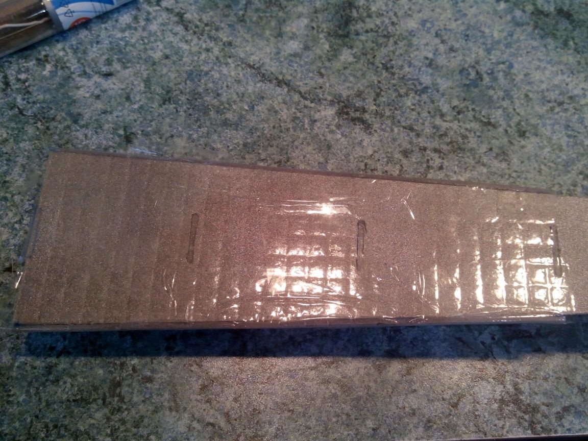
We glue the upper part of the lid by adhesive tape on the outside with gargot, and press the strips from the inside with a fork.
Glue all half frames with glue and glue the top.
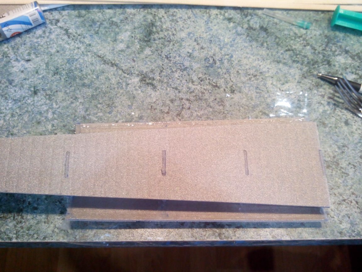
Gently bend the top, fix with adhesive tape on all sides and leave the glue to dry completely.
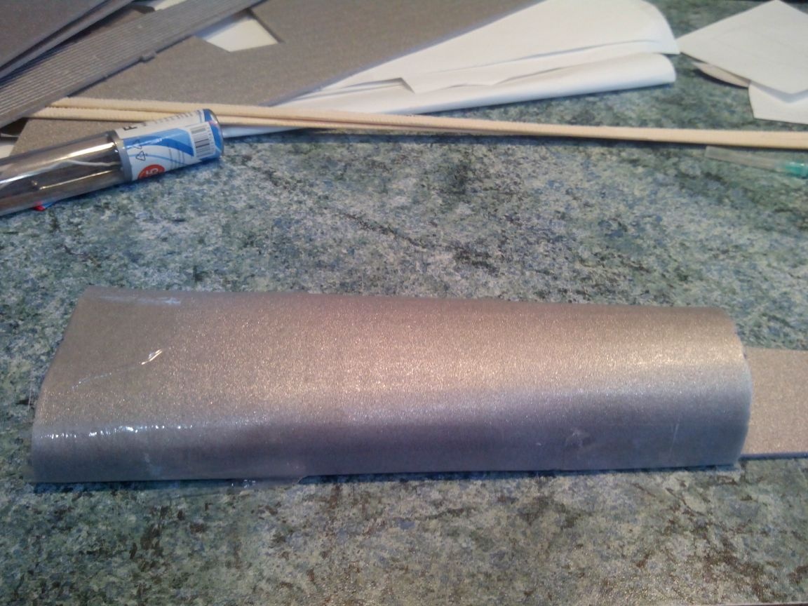
We cut out the side strips from the depron, and a lantern will be glued to them.
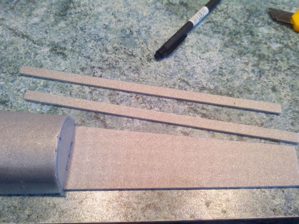
Cut out the back.
Glue the sidewalls and the back.
After the glue dries, we remove the entire adhesive tape and sand the edges if necessary.
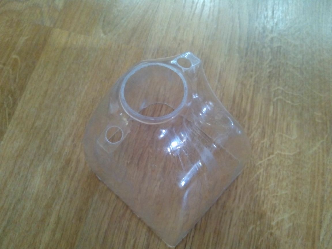
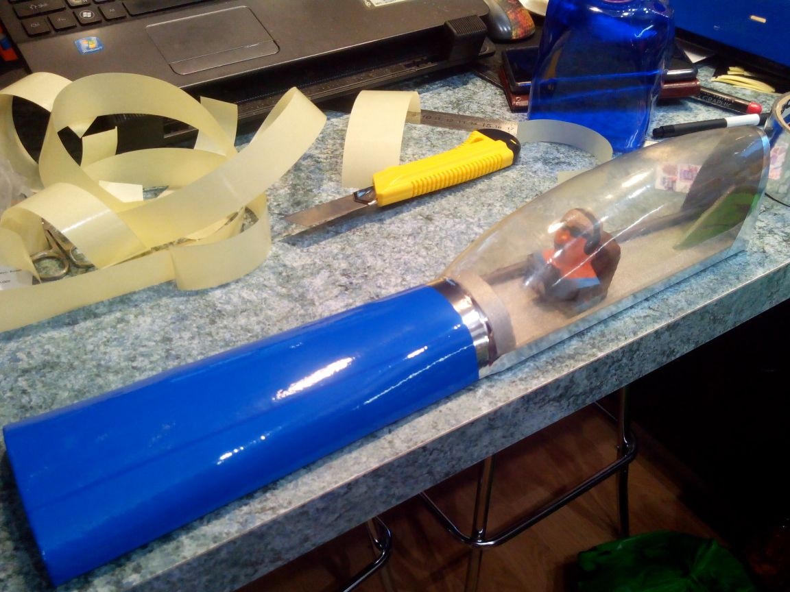
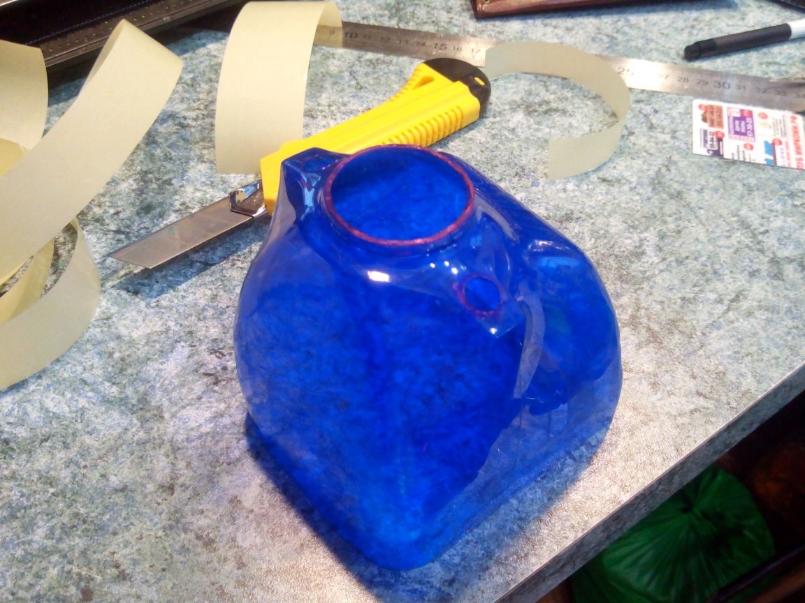
The lantern is made by the method of heat shrink bottle on a blockhead.
How to make a doodle for a lantern, I told in this article.
We wrap a 2-liter doodle in a bottle and fix it with screws.
We heat it with a building hair dryer, then cut off the excess and skim the inside from the inside out.
You can make a pilot figure so that the cabin is not empty.
I took this “pilot” from a broken Ryan STA model, about which there is also a production separate article.
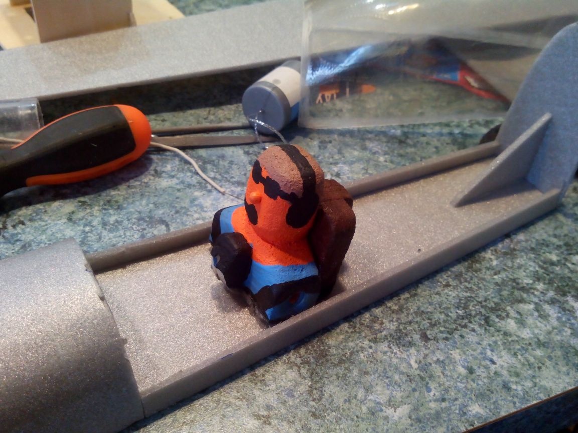
To stick the lantern to the lid, we make an improvised slipway of two slats and a sheet of cardboard.
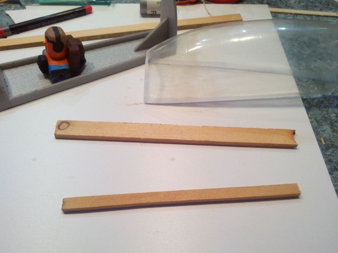
Glue the lantern with an epoxy-five-minute to the lid and clamp in the slipway until it dries completely.
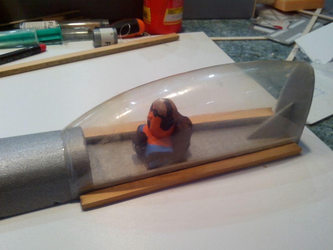
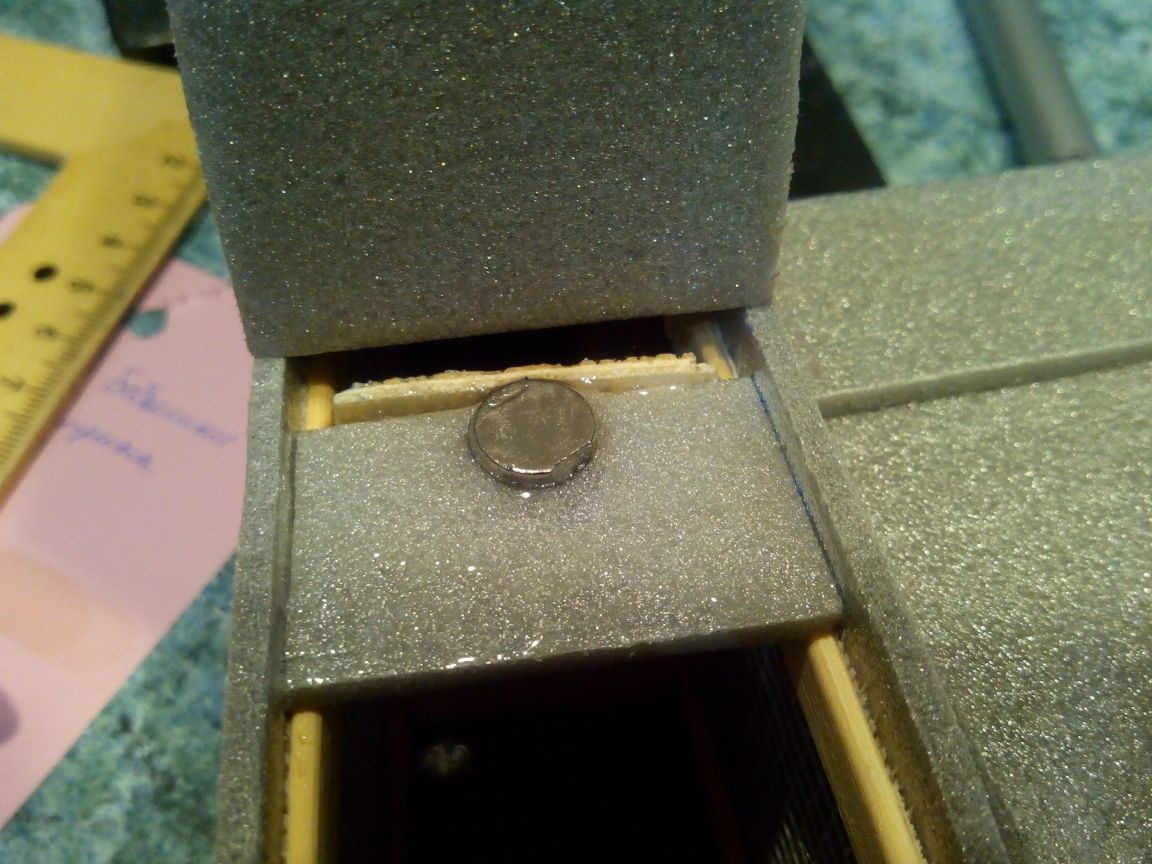
We also attach a neodymium magnet to the lid on the epoxy.
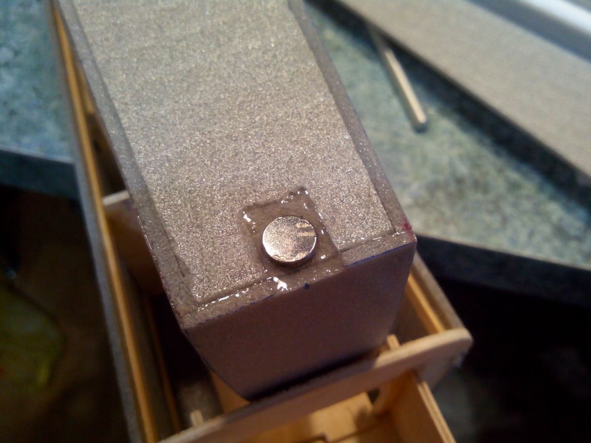
Glue the second magnet to the site in the fuselage.
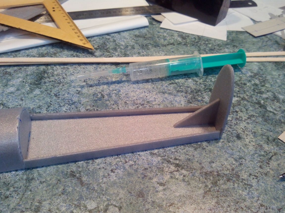
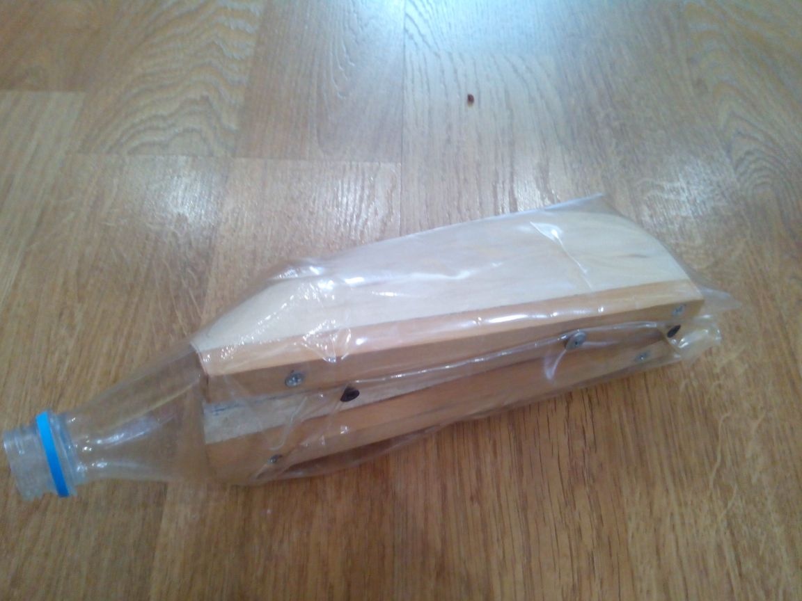
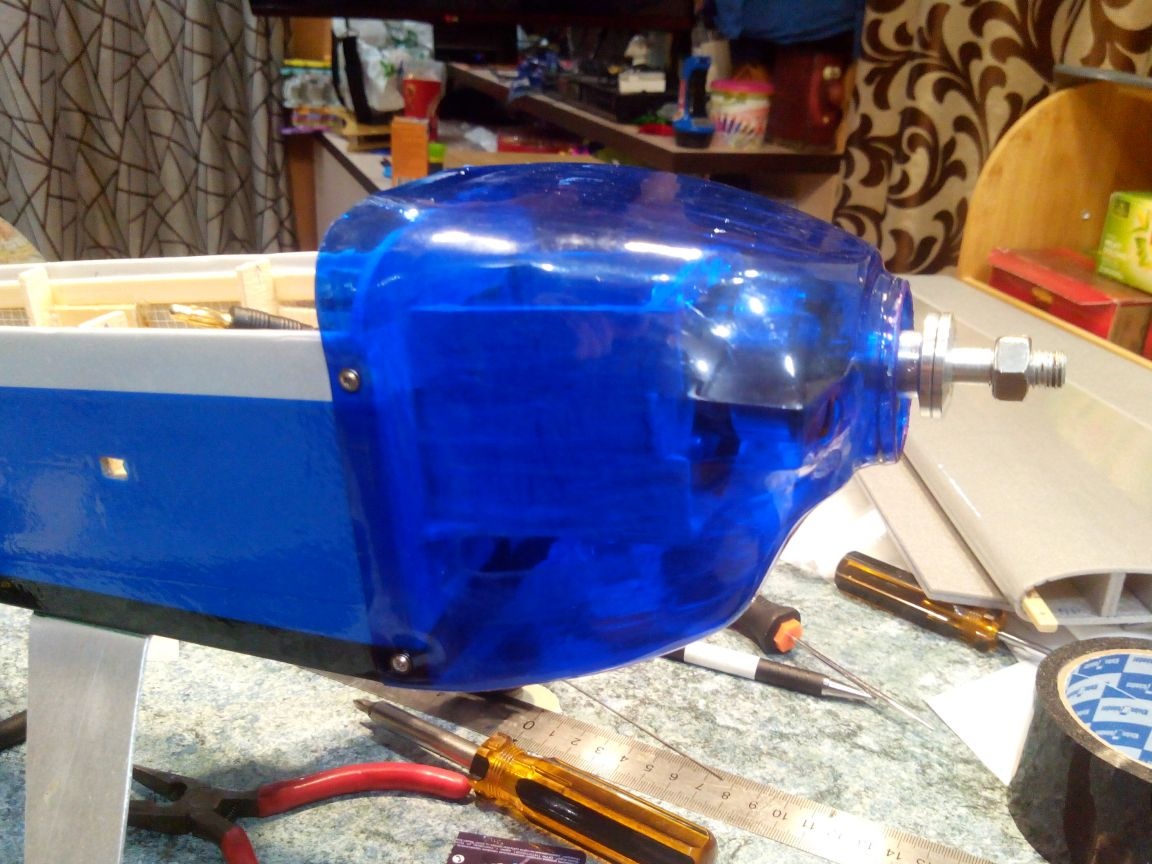
The hood will also be made using heat shrink method (“bottle technology”).
You can use an alternative embodiment of the hood - from epoxy and pantyhose. There is about it separate article.
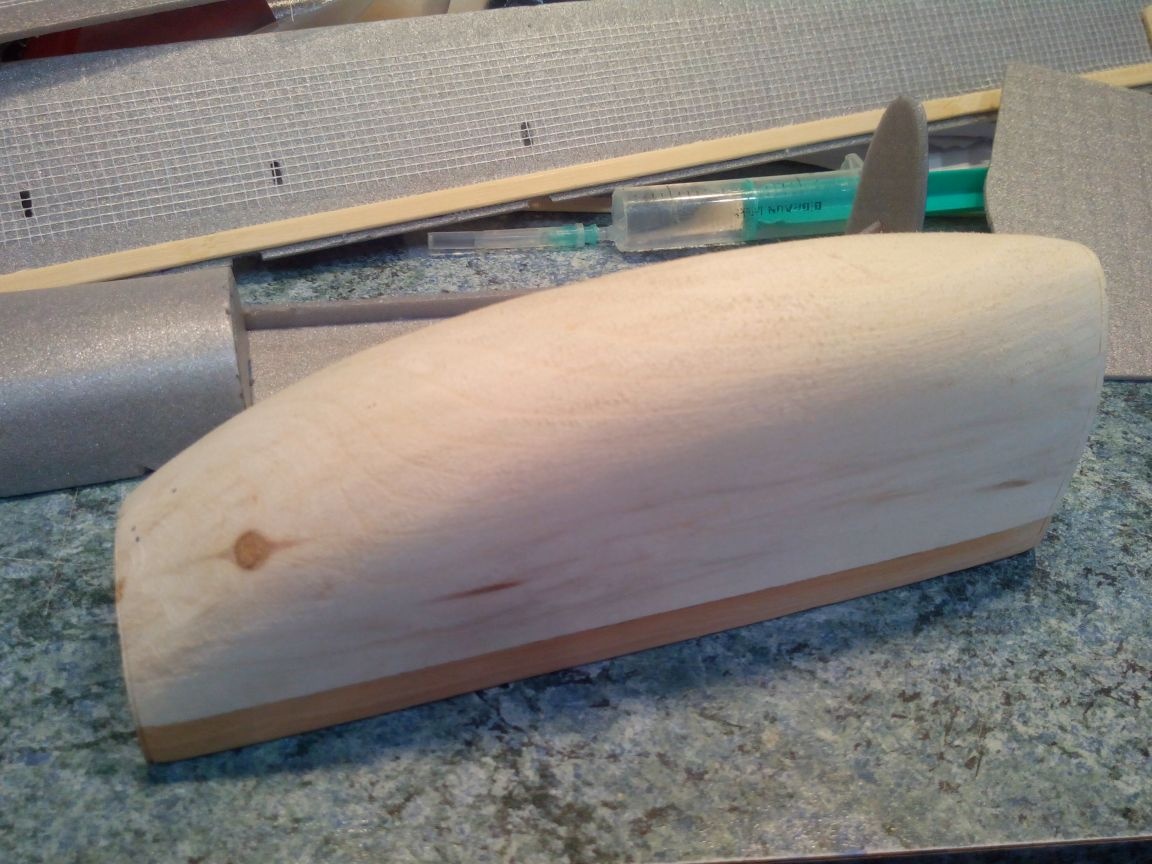
We make a hood block from a wooden block. The protruding parts are best cut separately and glued with PVA glue (I talked more about making a similar doodle here).
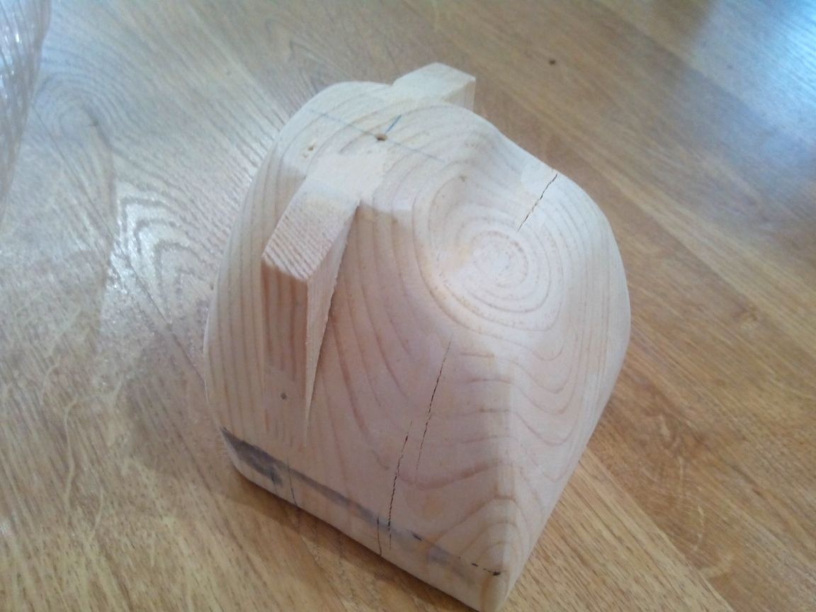
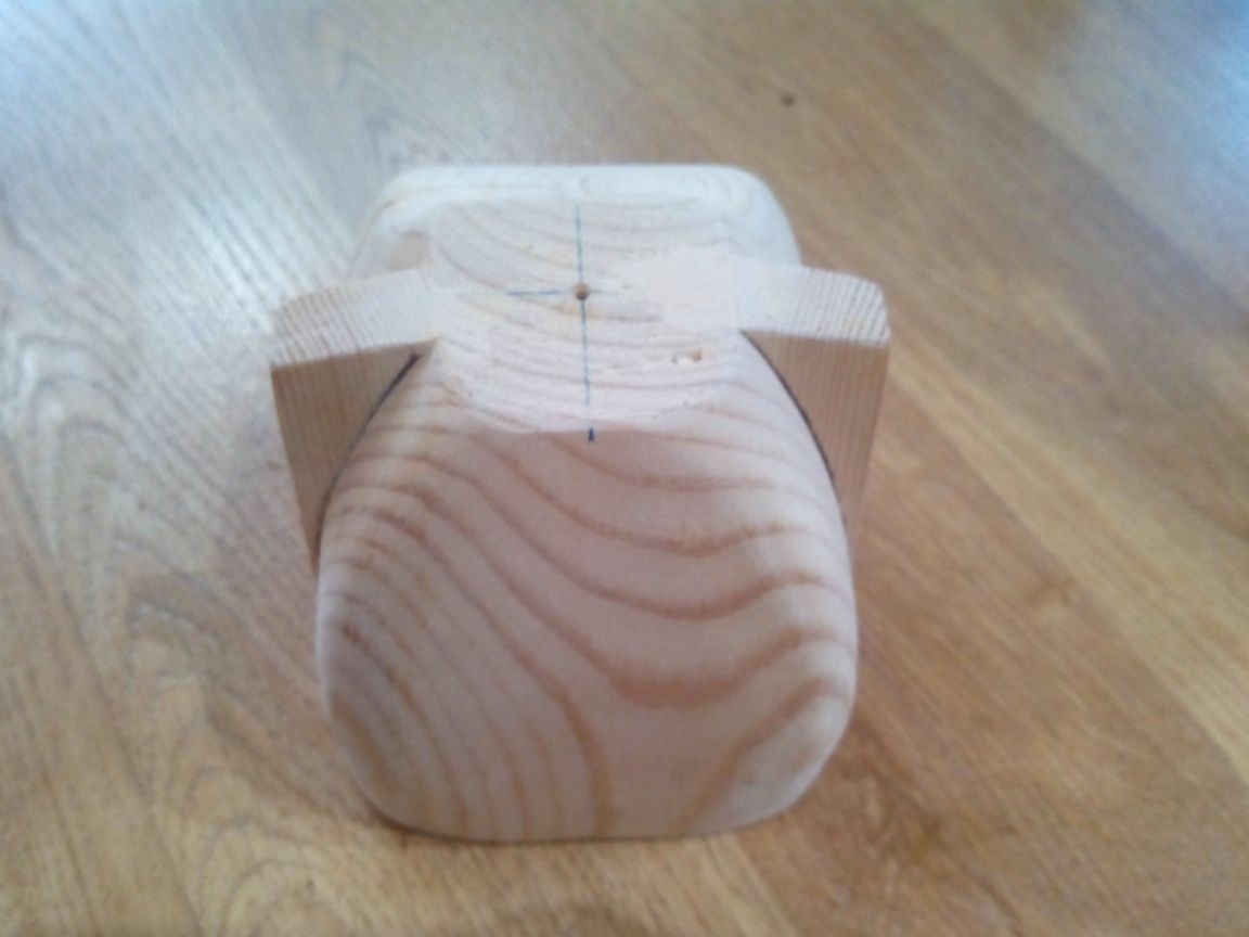
A bottle will need 4 or 5 liters.
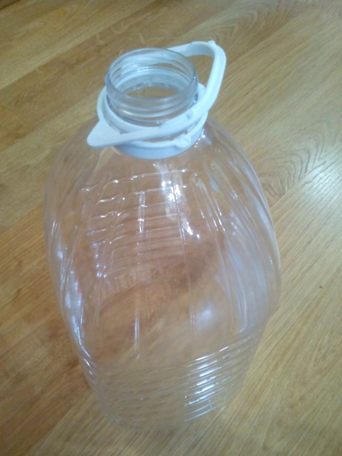
Cut off the bottom of the bottle, wrap a block in it and fix it with screws. The throat through the lid is also fixed with a self-tapping screw, so that during shrinkage it does not slip to the side.
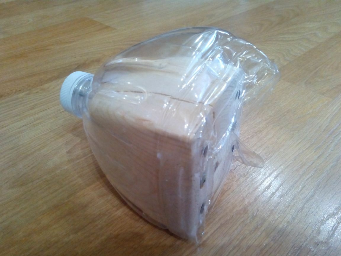
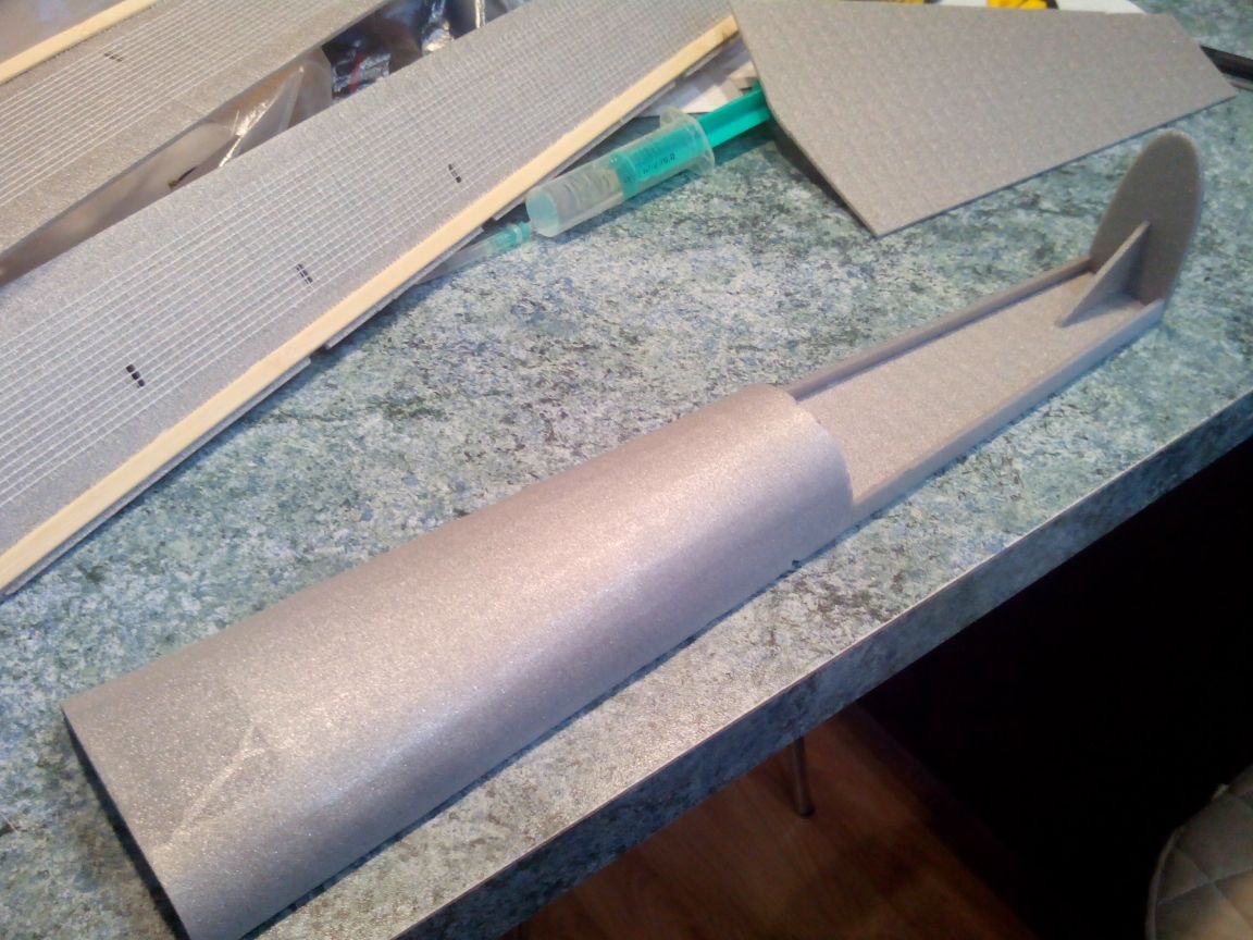
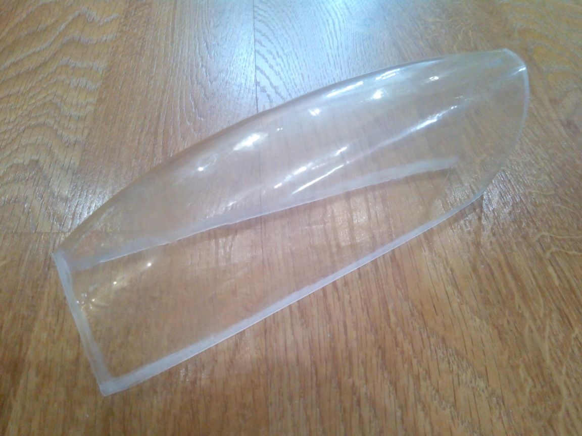
We heat the bottle with a construction hairdryer from all sides until completely aligned with the blockhead.
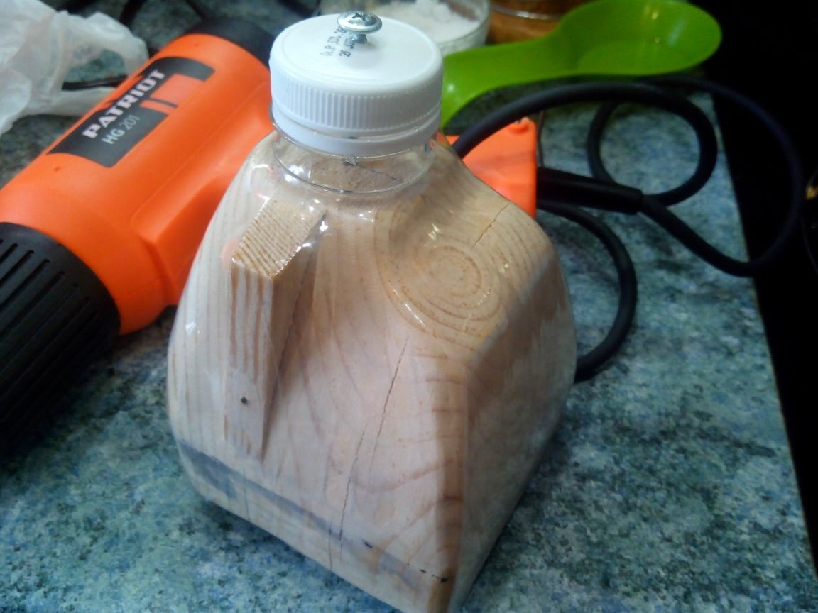
Then cut off the excess from the bottom, cut off the neck and drill holes for ventilation.
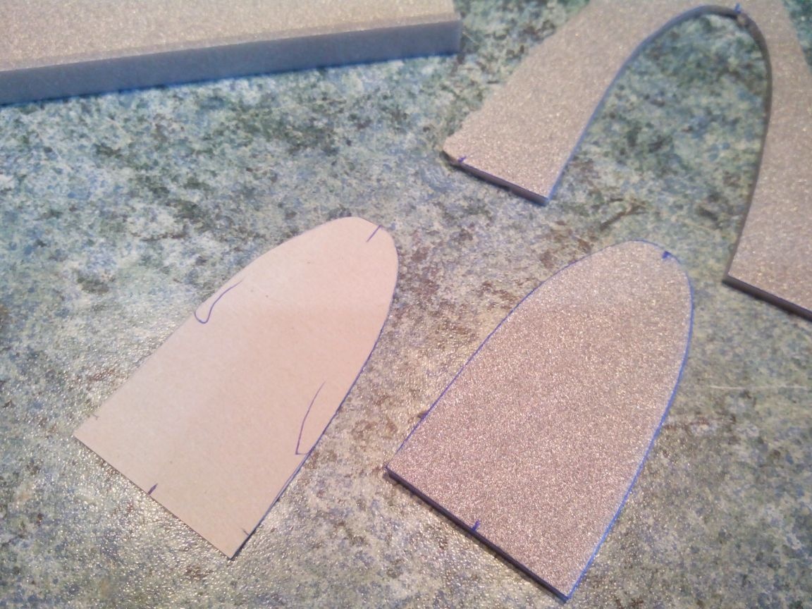
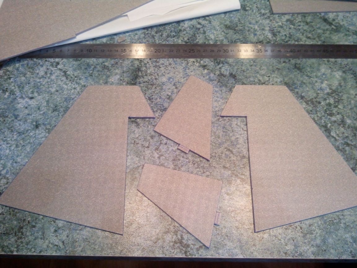
Step 3. Production of the tail.
According to the patterns, we cut out the details of the keel and rudder.
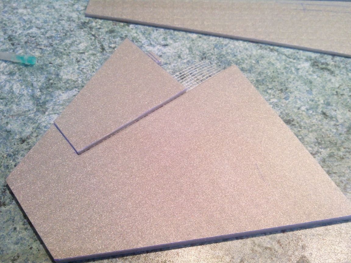
With an emery cloth, we grind the back of the keel at an angle of 45 degrees and connect the serpentine with the rudder.
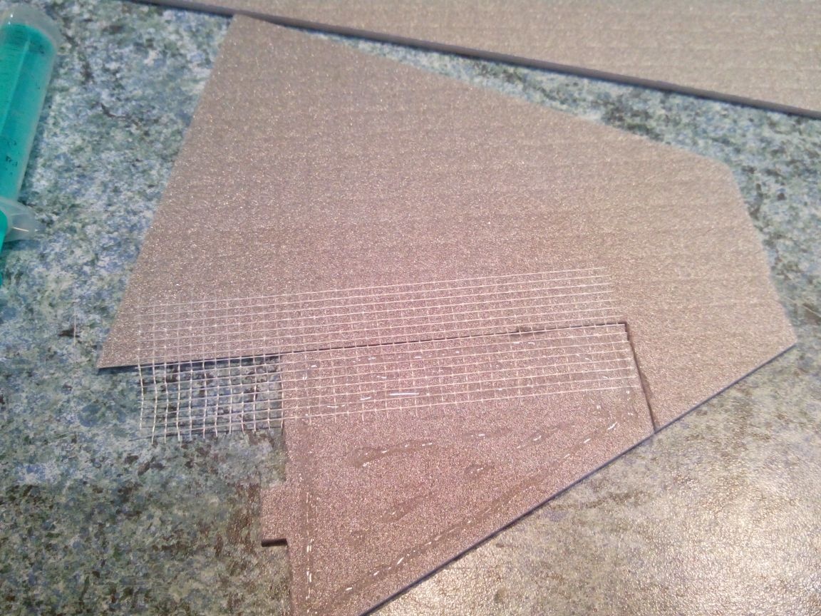
We glue the second part of the keel and rudder and send it under the press until completely dry.
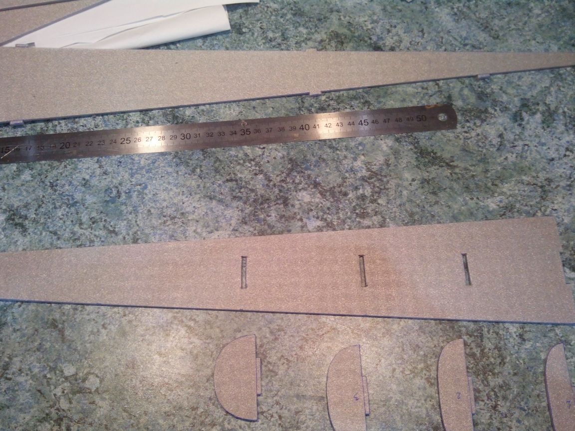
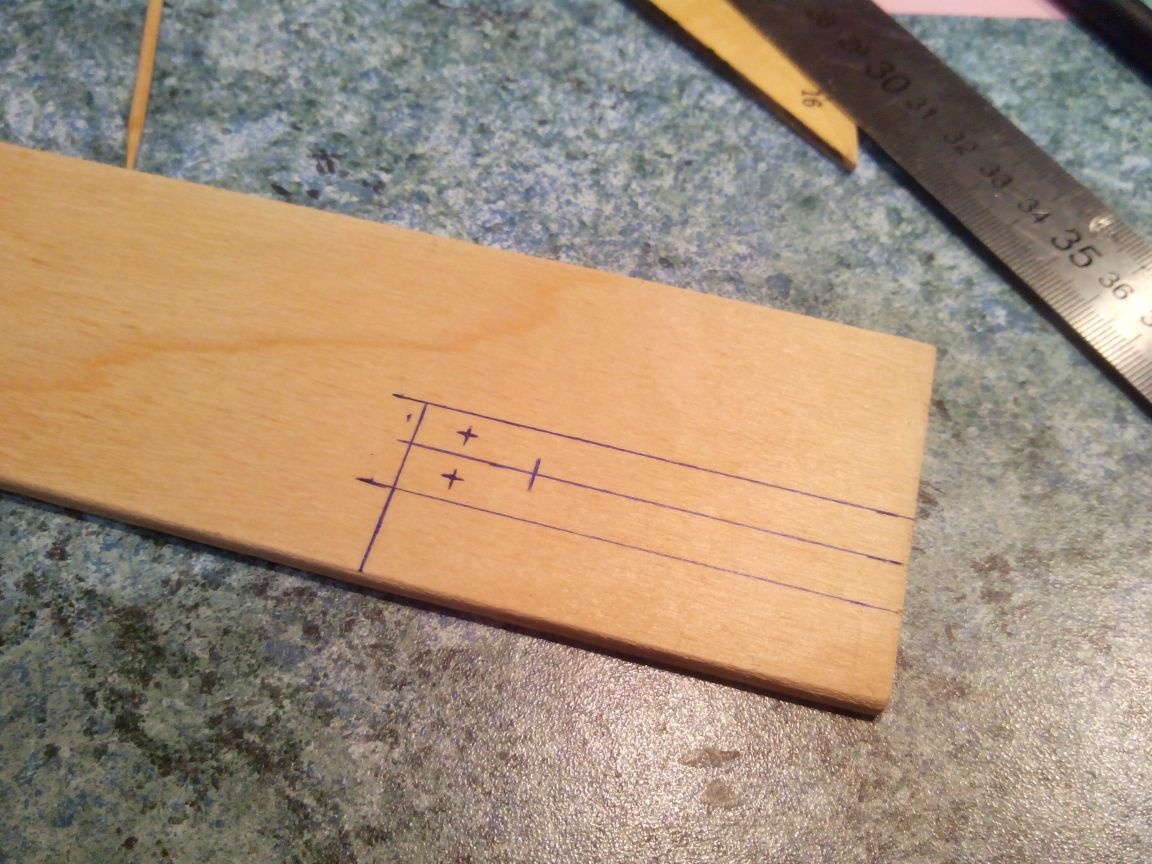
We draw the details of the horizontal plumage on the depron.
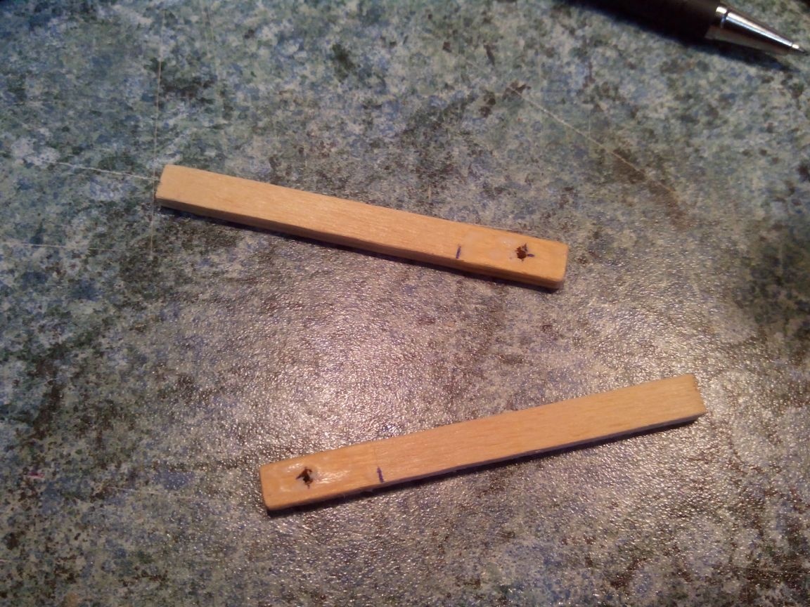
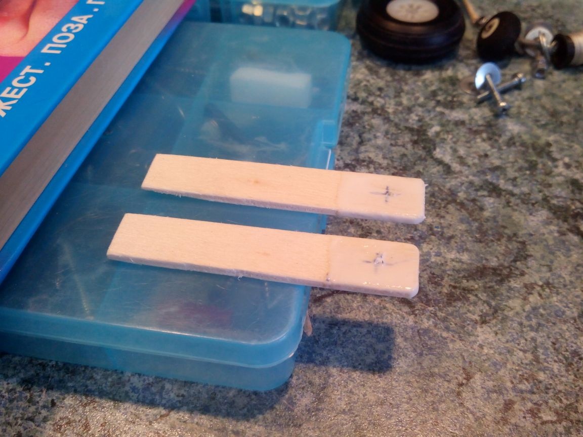
Cut the parts with a cutter. We bend the synchronizer of the halves from the steel wire and make a small depression in the elevator to sandpaper the reinforcing strip (ice cream stick).
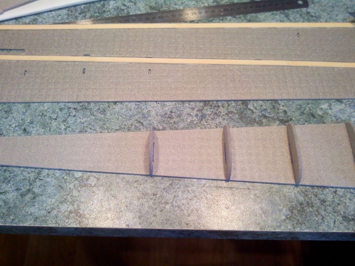
We glue the rail and glue the synchronizer.
We make loops from a sickle. She also reinforces the elevator along the edges and in the area of the wire synchronizer.
Lubricate all parts with glue.
We glue the second halves of the elevator and stabilizer and leave it under pressure until the glue dries.
In the rudder we make a small cutout so that it does not interfere with the movements of the elevator.
In the tail of the fuselage we make cutouts for the keel and stabilizer.
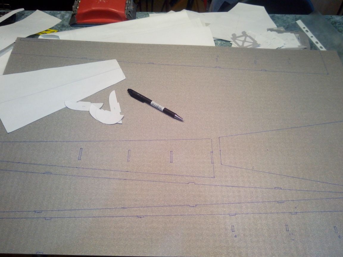
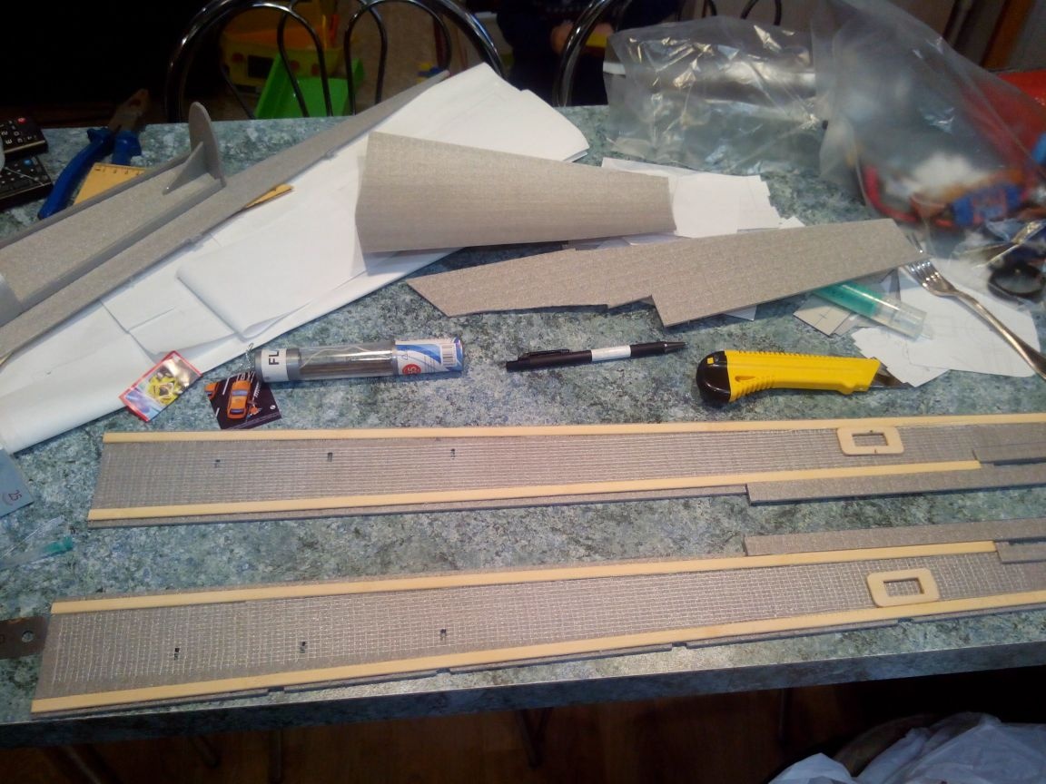
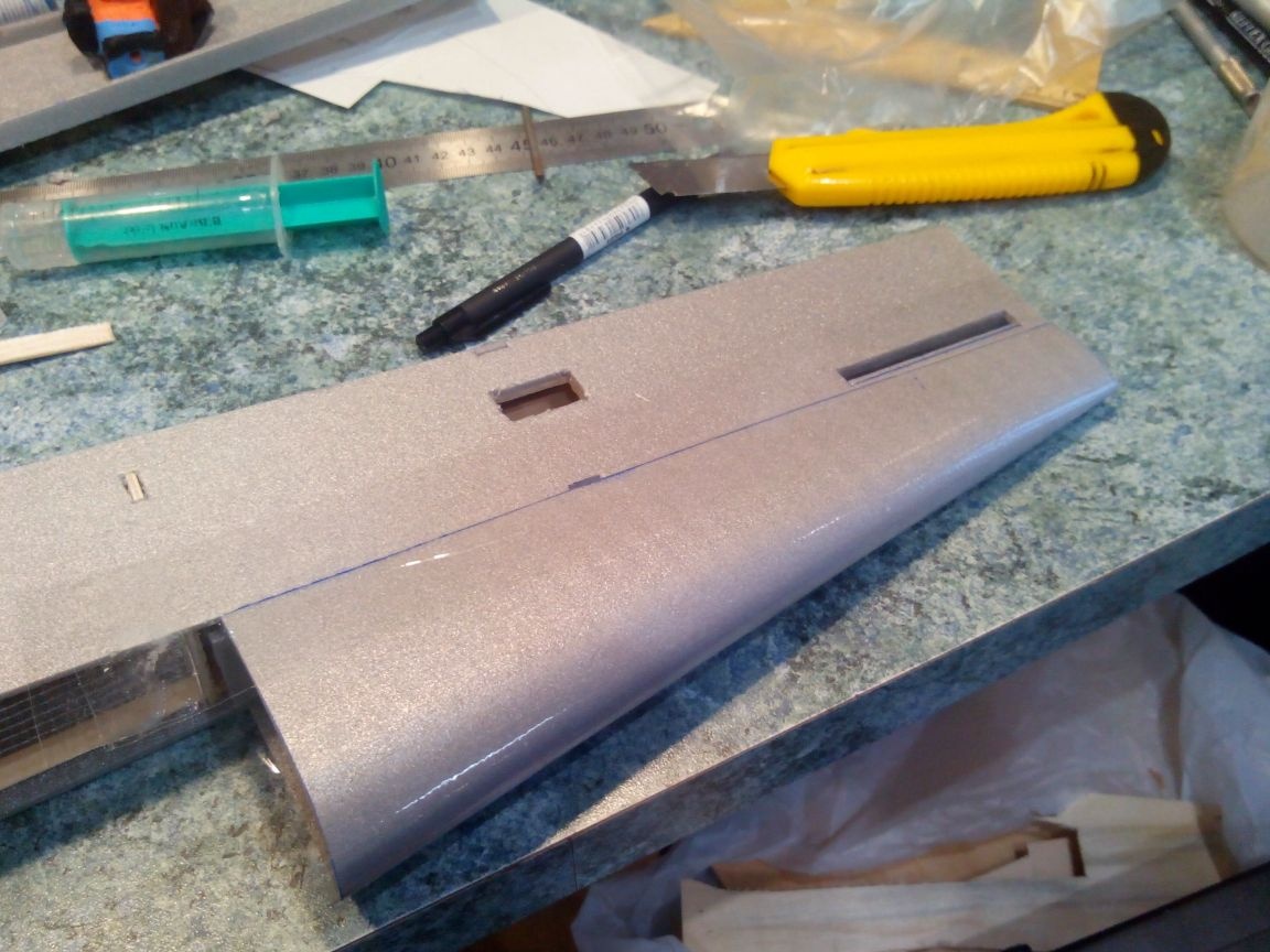
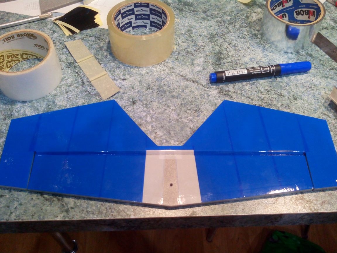
Step 4. Making a wing.
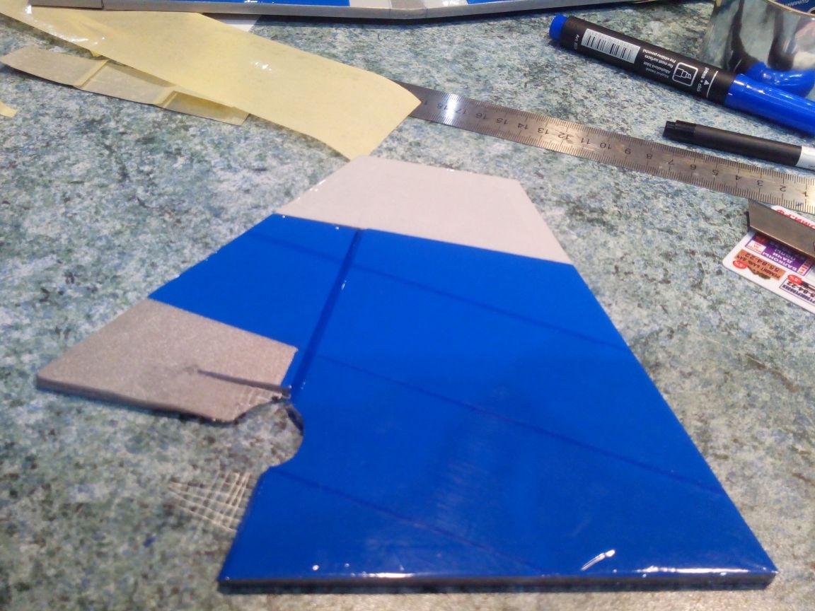
We draw the details of the wing and ailerons on the platform.
We cut out the details and glue it on the outside with tape, you can even immediately in the desired color.
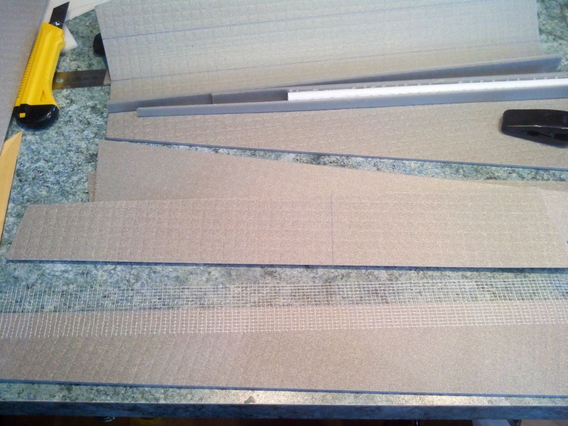
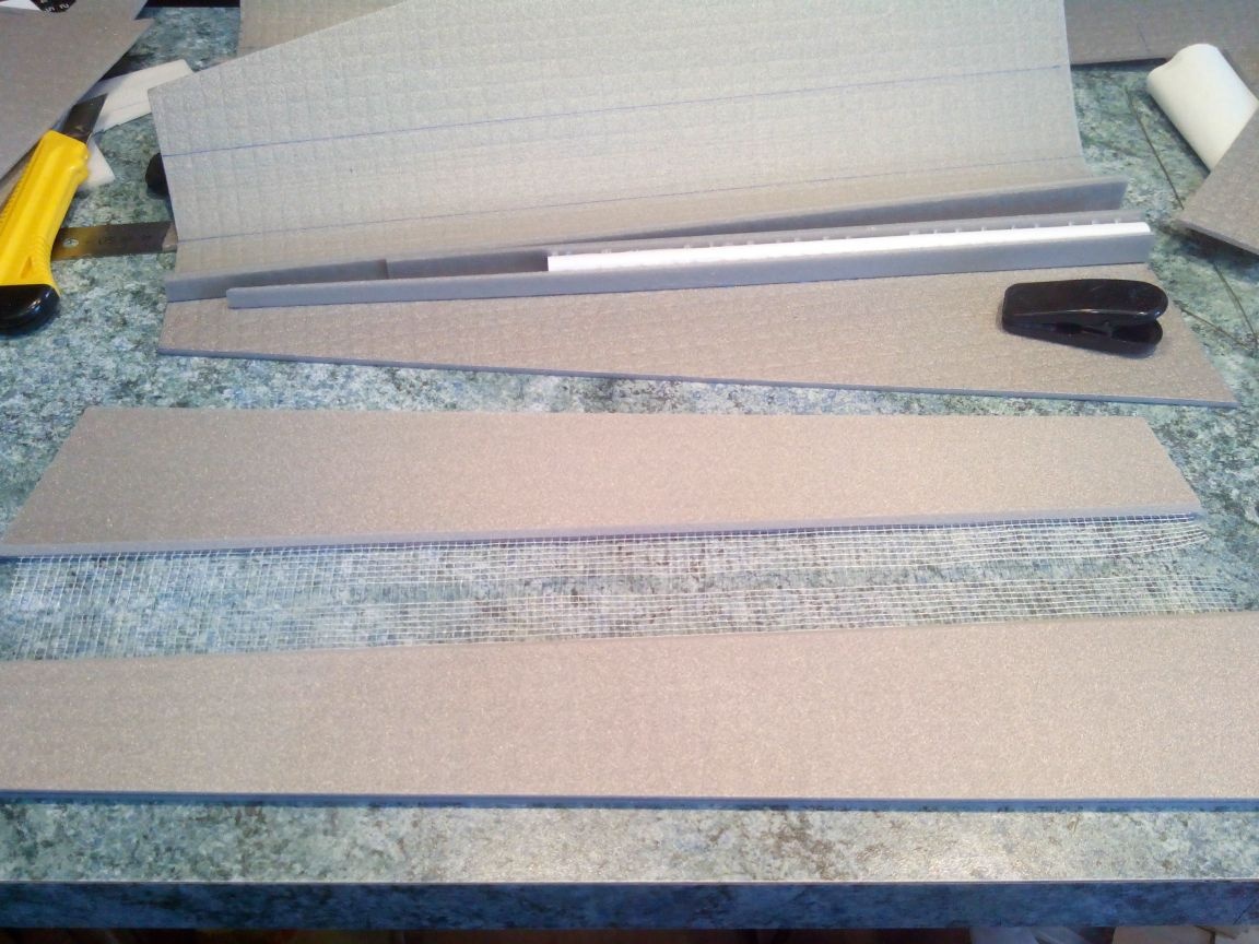
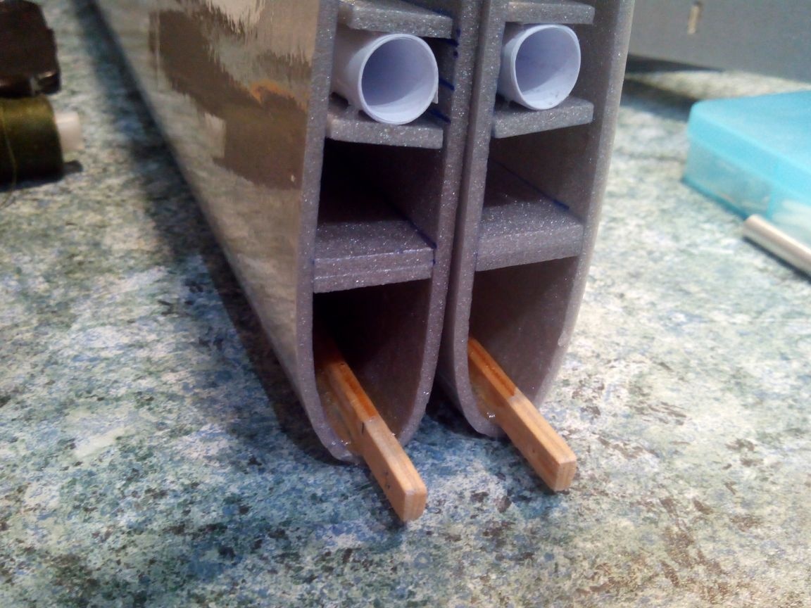
Cut the spars from the depron.
Glue depron spars to the wing blanks.
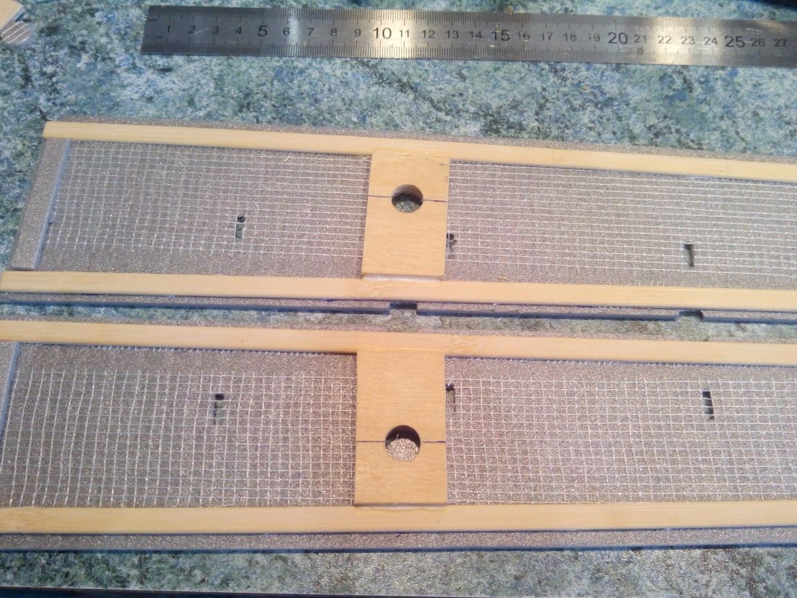
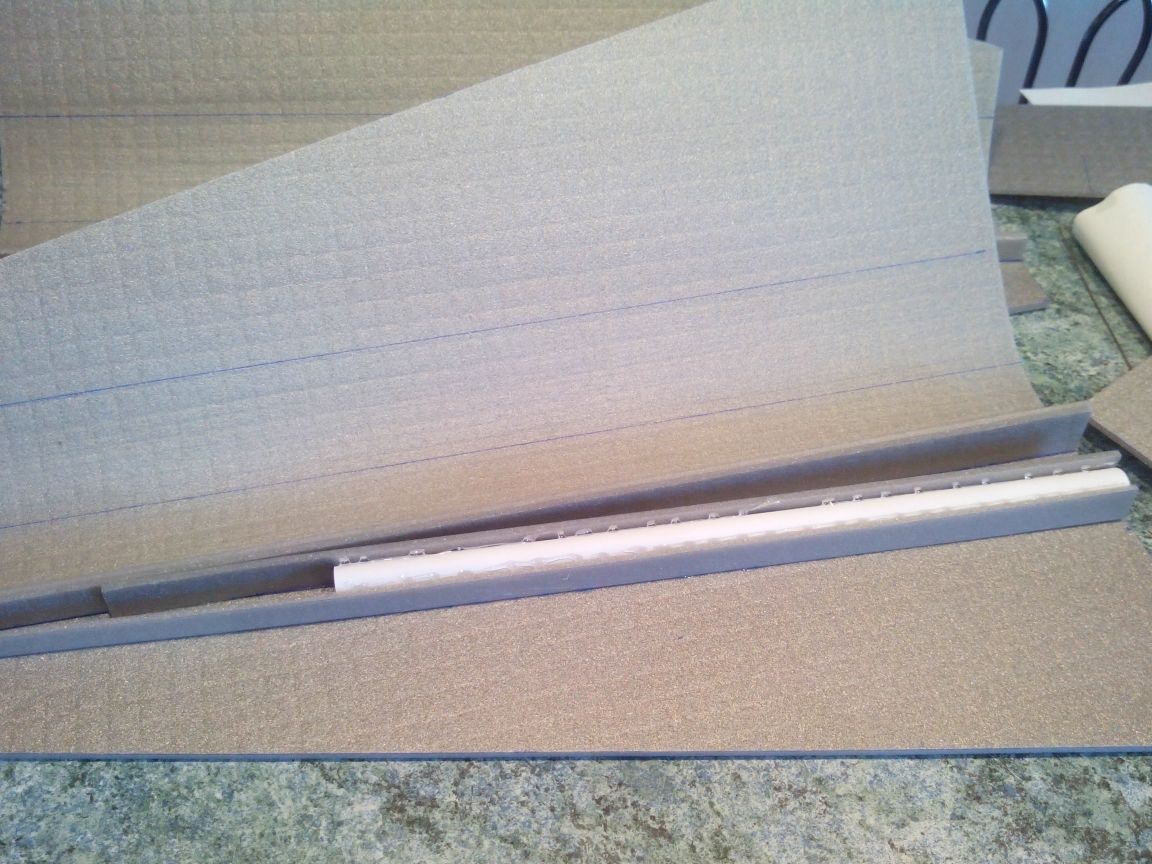
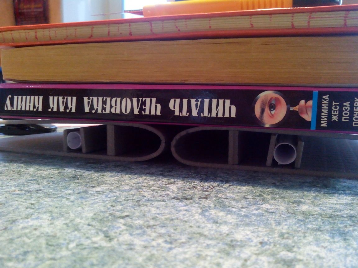
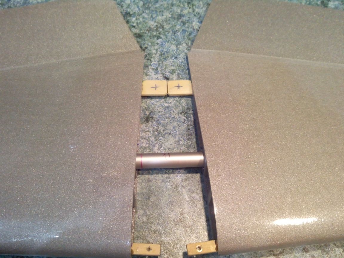
From plain A4 paper on a spar tube, twist and glue two tubes.
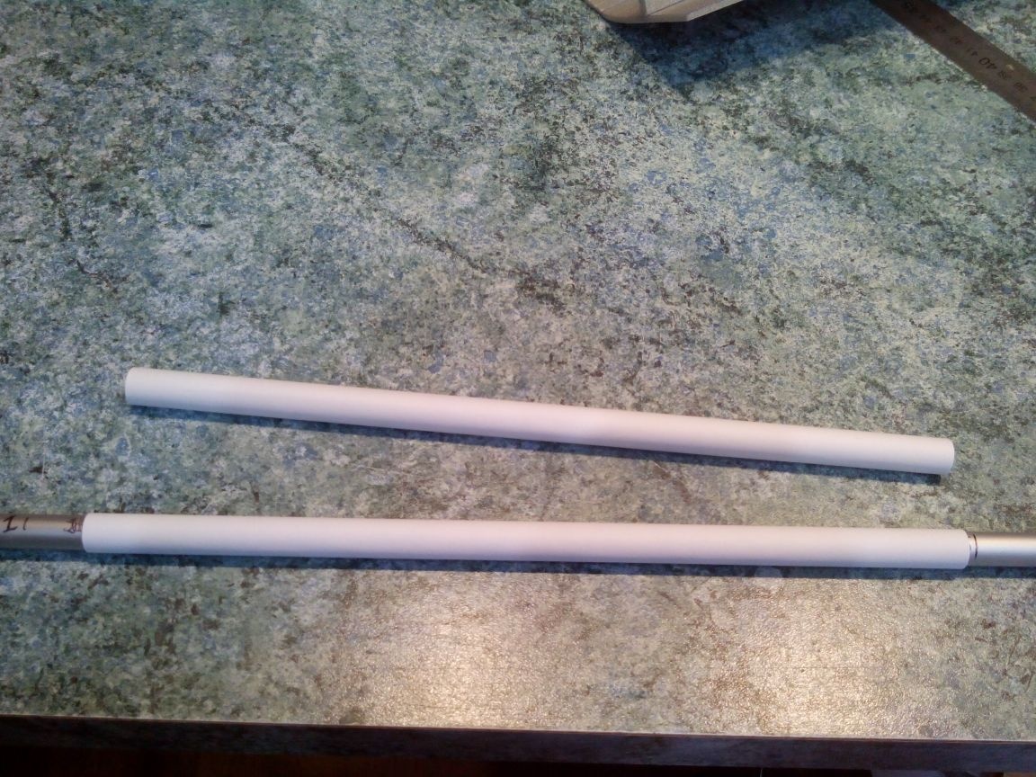
From the depron we cut out additional spars for paper tubes.
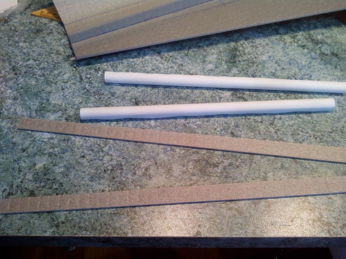
We glue spars and tubes together, making them a kind of sandwich with a tube inside.
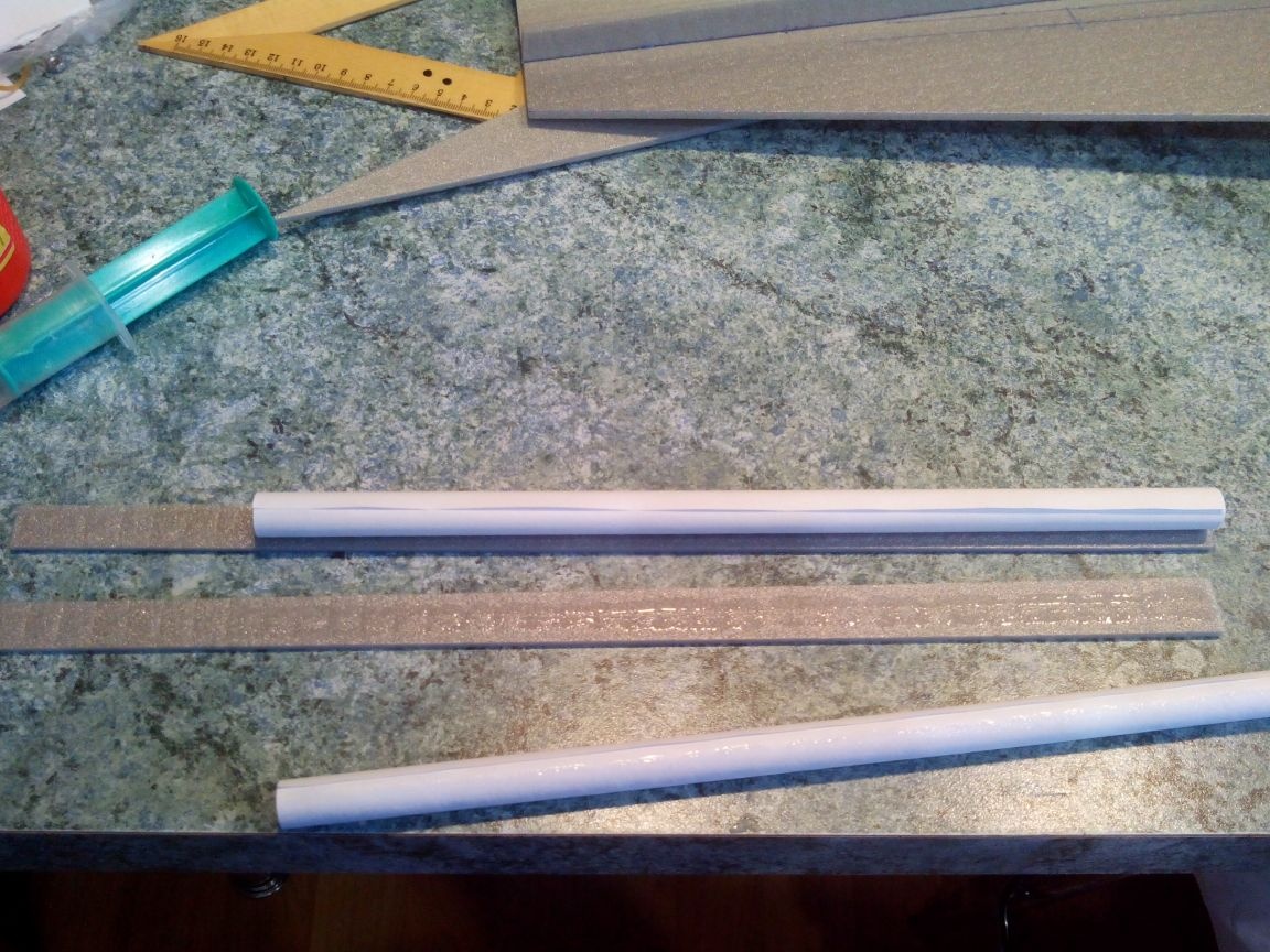
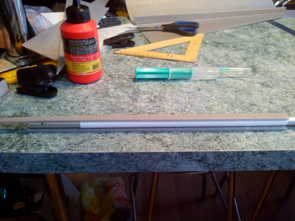
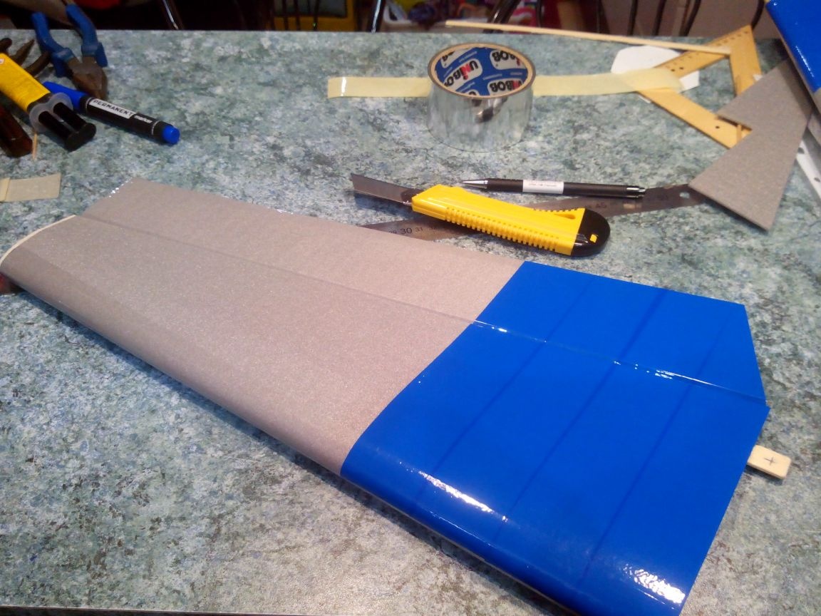
Glue the resulting structures to the wing blanks.
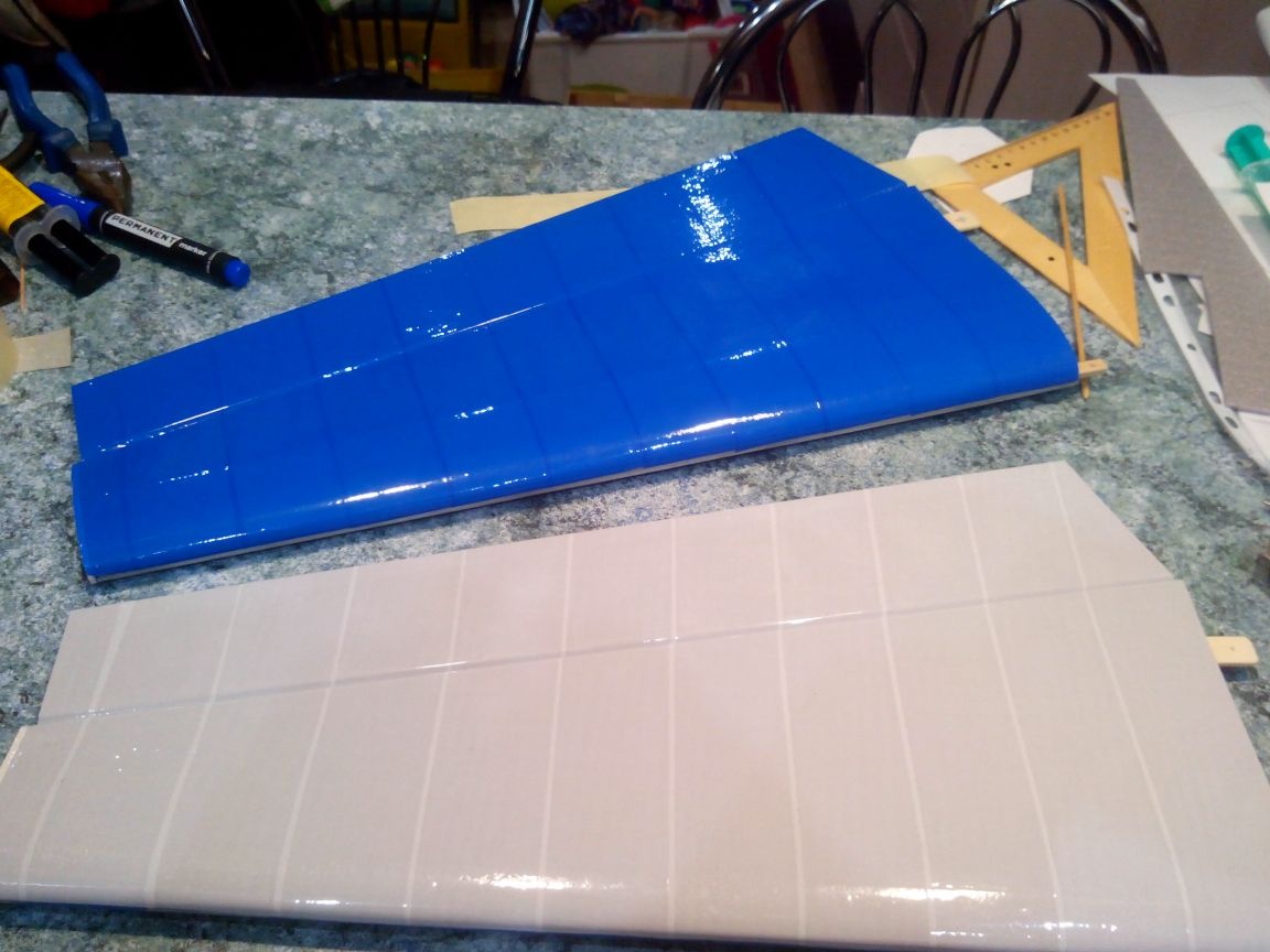
Gently bend the workpieces, glue to the first spar and leave until completely dry under pressure.
We cut out the details of the ailerons and glue the loops from the sickle.
We glue the second halves of the ailerons, thus sealing the loops from the sickle inside.
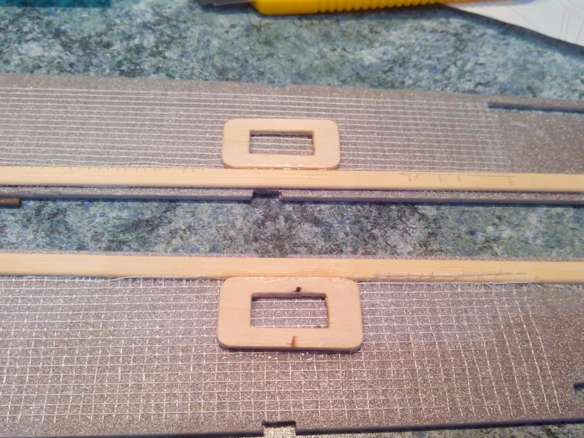
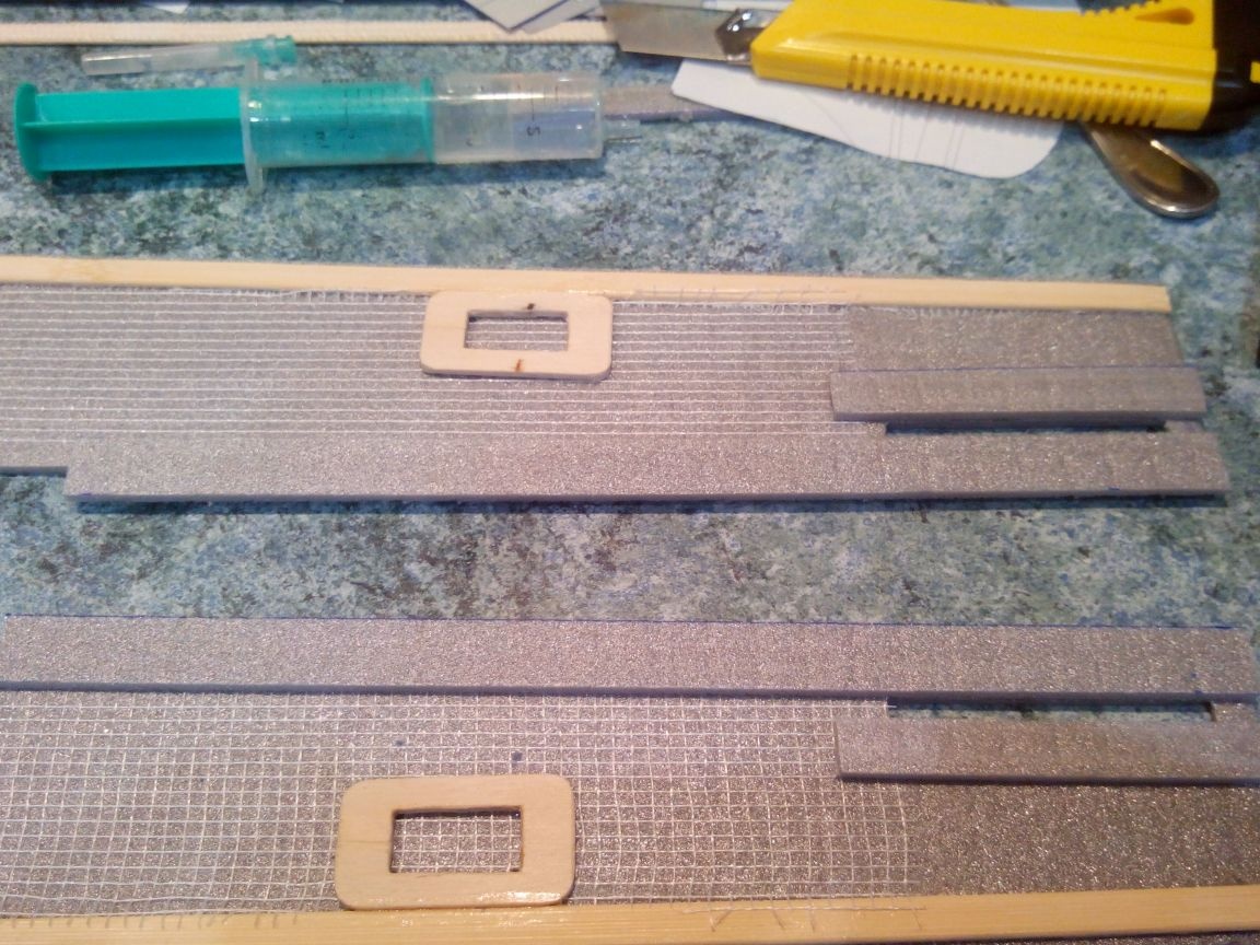
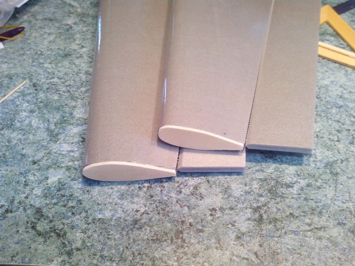
We cut out the details of the wing fastening from plywood and make holes in them with a thin drill.
Glue the parts onto the epoxy into the wing so that they protrude about 2 cm outward.
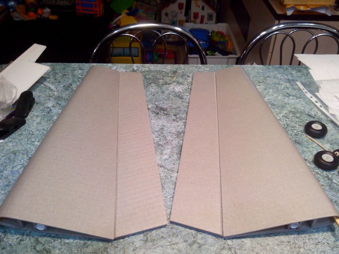
We glue the wing consoles completely, immediately pasting the ailerons.
We cut out the details of the wing fastening for the trailing edge from plywood and make holes in them.
We glue the mounting parts in the back of the consoles on an epoxy.
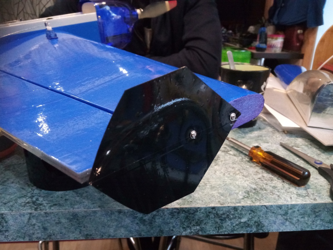
We cut the wingtips from thin plywood and glue them.
We fasten the winglets of thin plastic from the packaging to the tips with small screws (they can be pasted with adhesive tape in the desired color).
To fix the wing consoles in the sides of the fuselage we make holes.
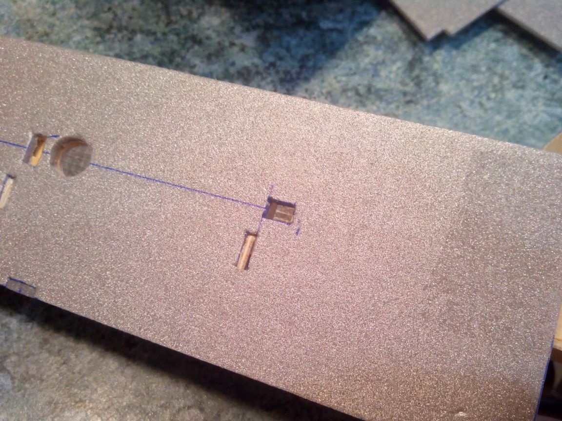
Inside we glue the plywood pads to which the consoles will be screwed.
So that the holes do not become loose during operation, we glue small L-shaped parts from plywood from the inside.
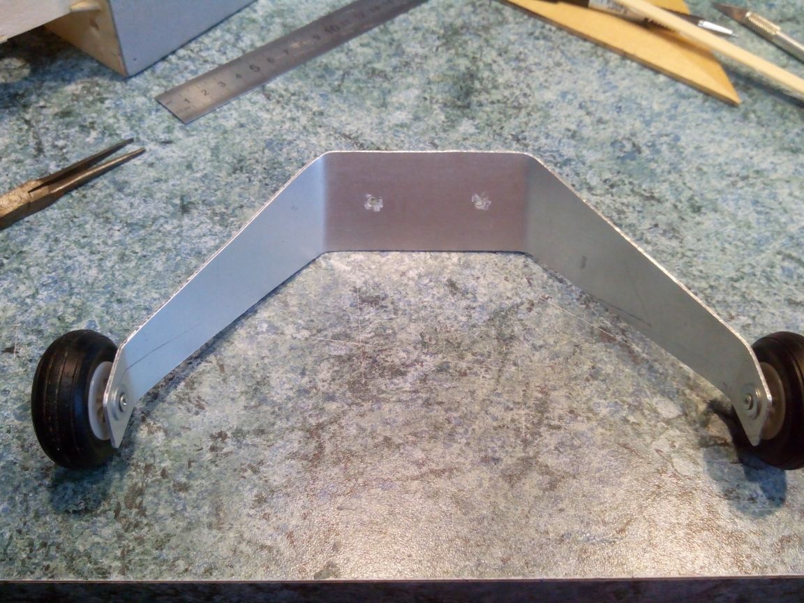
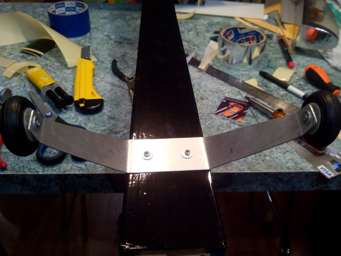
Step 5. Making the chassis.
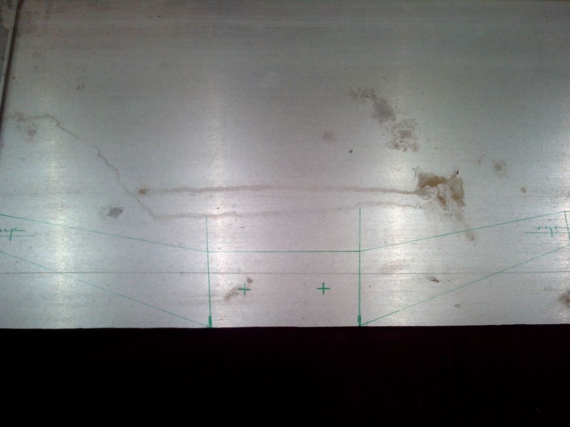
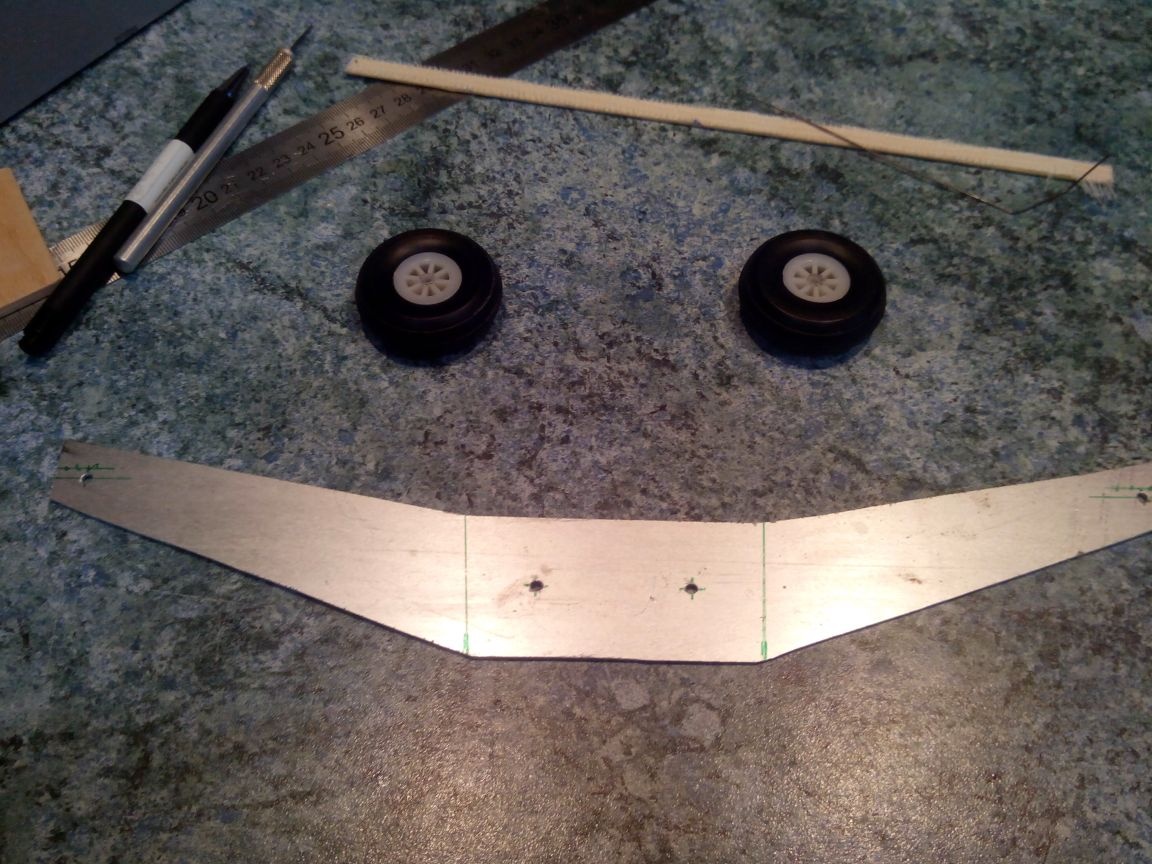
On a sheet of duralumin (for example, a shelf-pallet from an old refrigerator), we draw a scan of the chassis rack.
Using a jigsaw or a hacksaw for metal, we cut the stand and drill holes for the axles and for the mounting bolts.
We bend a rack in a vice.
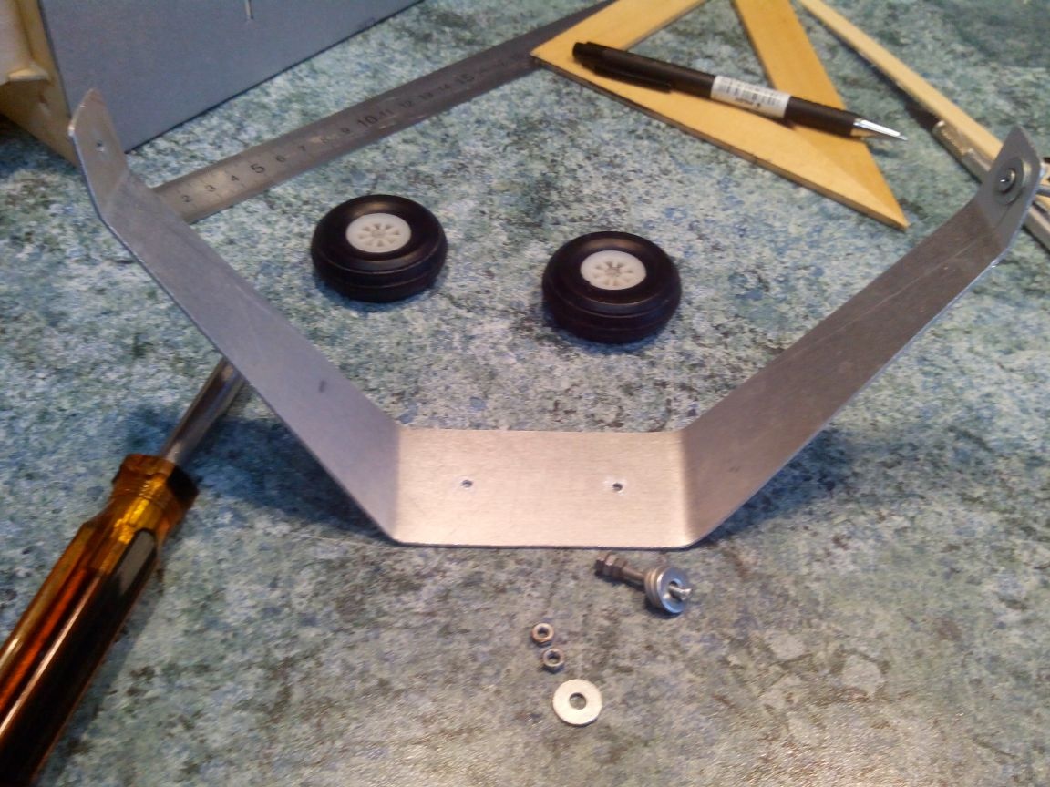
We fasten to a rack of a wheel.
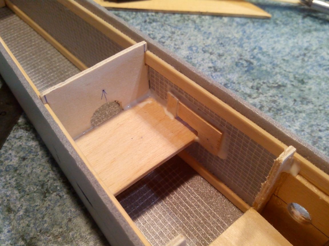
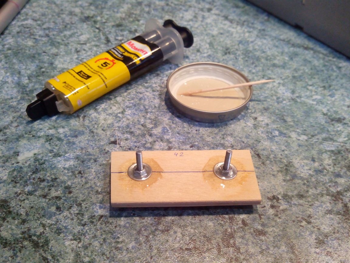
From plywood, we cut the platform under the landing gear.
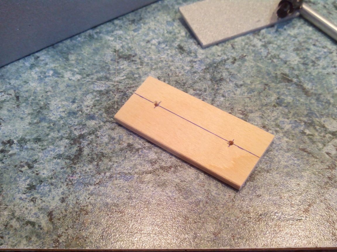
Using epoxy glue, glue nuts and washers to the pad.
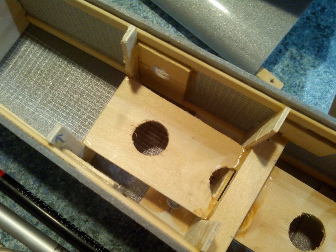
We glue the pad to the bottom of the fuselage from the inside.
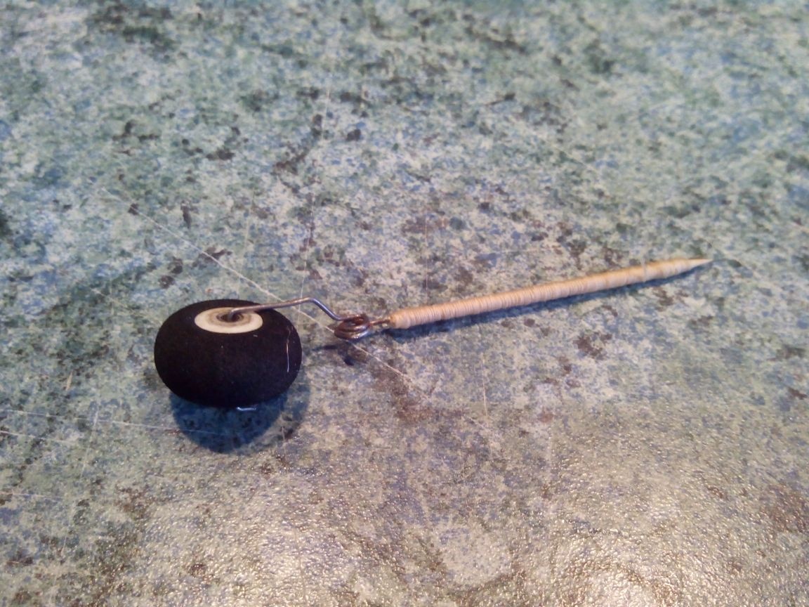
We bend the rear landing gear from steel wire, making a couple of turns so that there is shock absorption during landing.
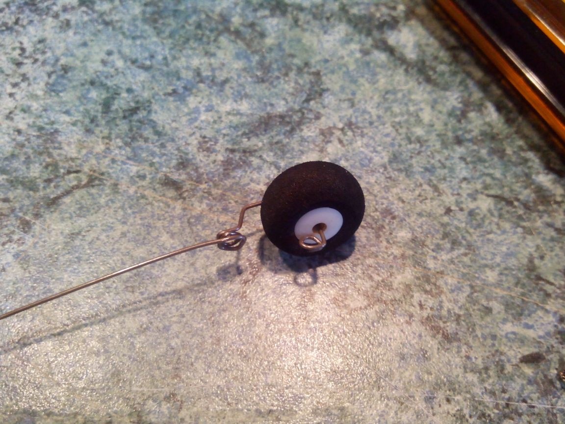
With a thread of glue, we wind a toothpick to the rack.
Step 6. Pasting and painting.
To glue the model, we use multi-colored adhesive tape and a base from self-adhesive films to cut the adhesive tape into certain parts, for example, the upper part of the gargot.
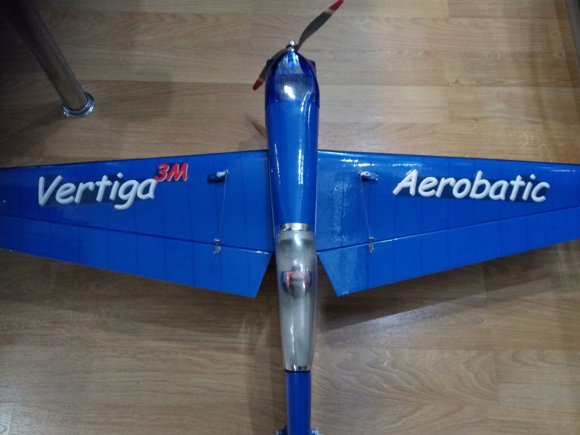
We glue the fuselage (colors, of course, choose to your taste).
We glue the lid in the color of the fuselage and add strips of metal tape around the flashlight.
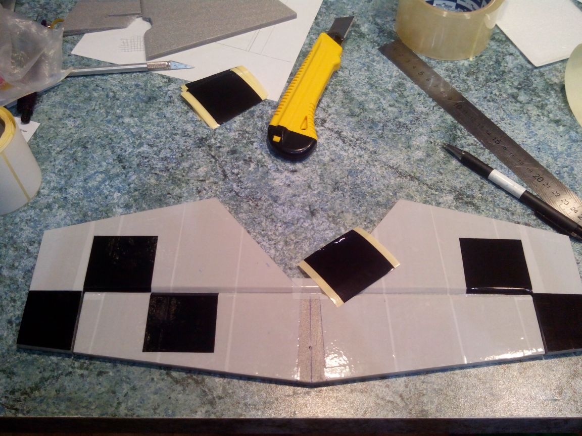
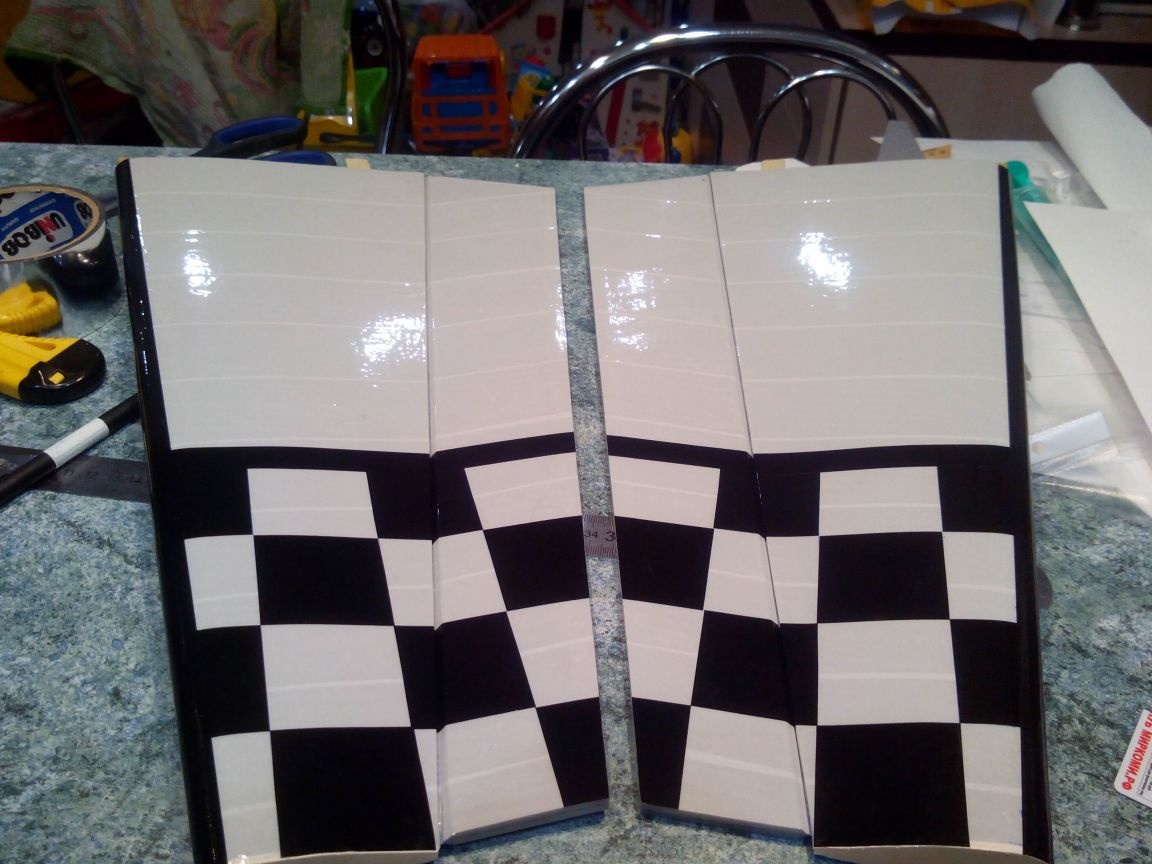
To glue the lower part of the wing and the stabilizer based on self-adhesive films from black tape, cut out the squares.
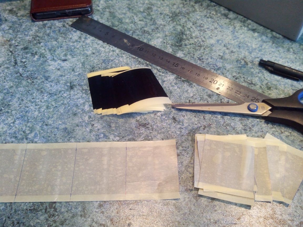
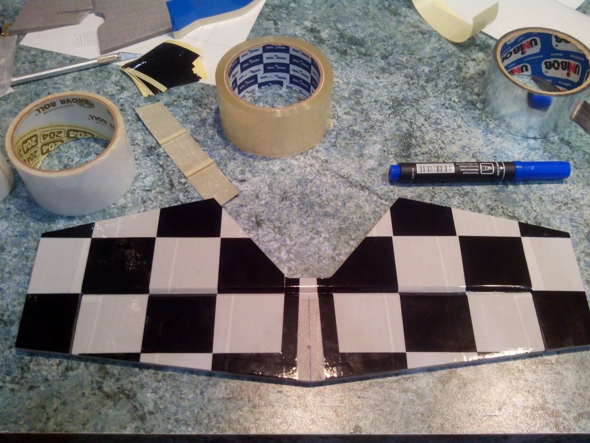
First, glue the stabilizer from the bottom with white tape, then add the black squares to make a checkerboard.
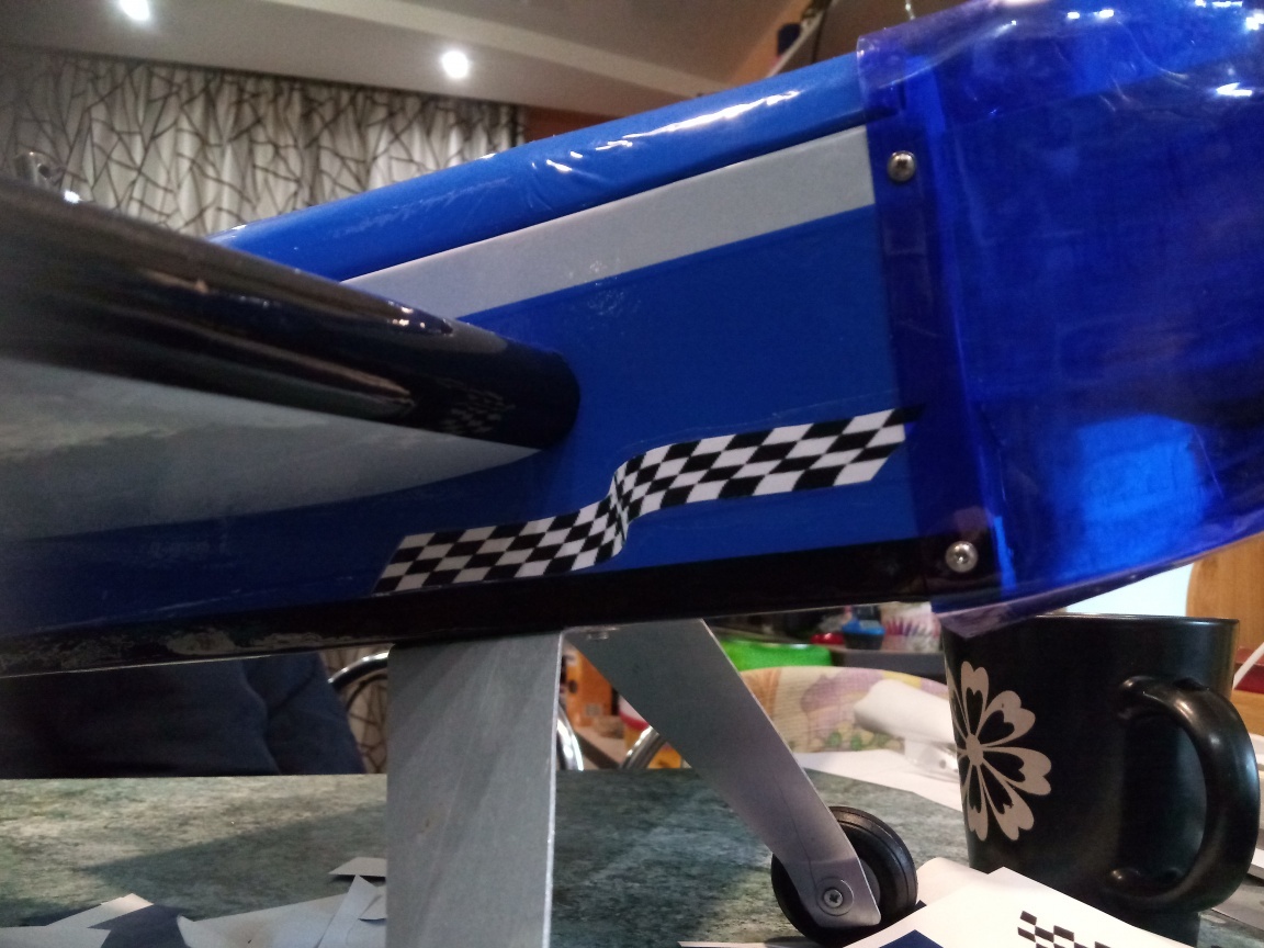
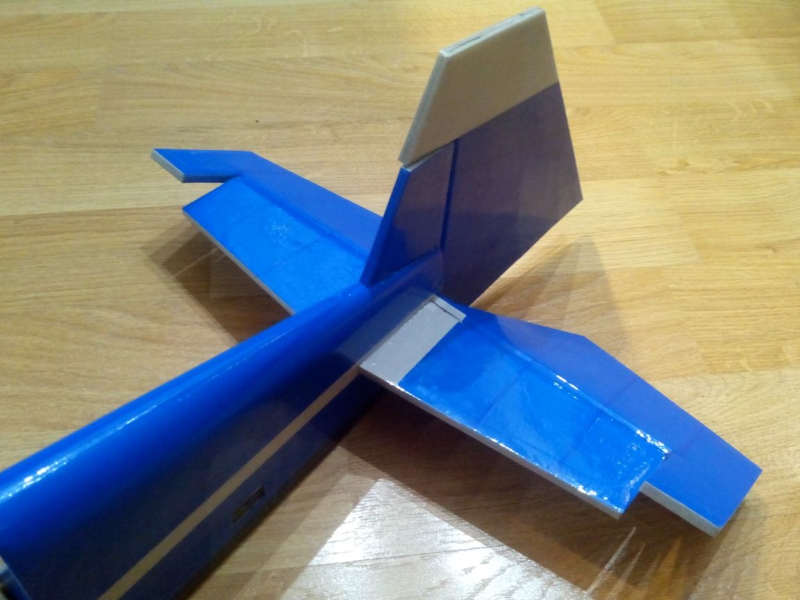
Glue the stabilizer on top in fuselage color.
We glue the keel and rudder.
It is better to glue the wing consoles by analogy with the stabilizer - the top is in the color of the fuselage, and the bottom is in contrast, in the cage.
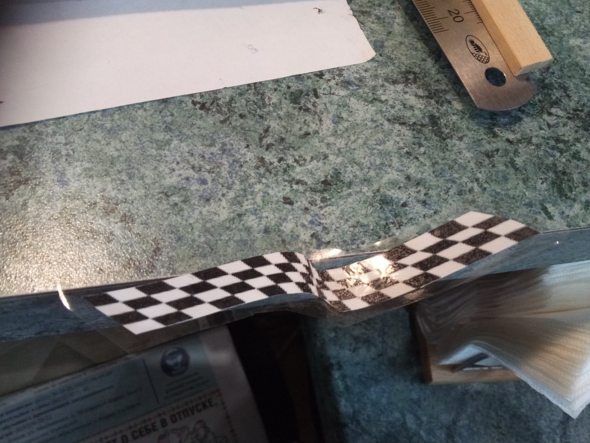
For beauty, the junction of flowers along the leading edge and the border of a chess cell can be sealed with thin strips of black tape.
We paint the hood with a marker inside the fuselage color.
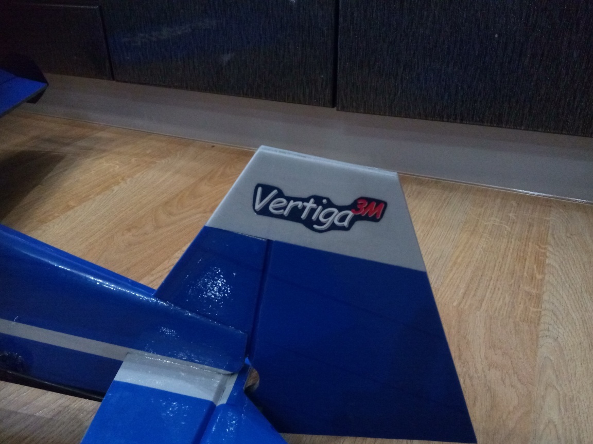
We print decorations for the model on the printer (there is an archive with drawings), cut them out and glue them on tape.
Then glue to the model.
Step 7. Assembly and installation of electronics.
Glue the tail to the fuselage.
We paste boars into the rudder and elevator.
We glue the tail chassis and add a small wire reinforcement for the rudder so that it does not tear off when landing.
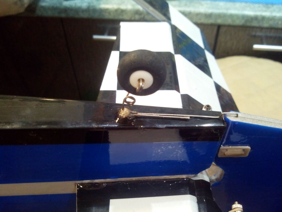
We paste tail servos with a thermo-gun.
We fix the traction of bamboo sticks and steel wire.
We fasten the landing gear.
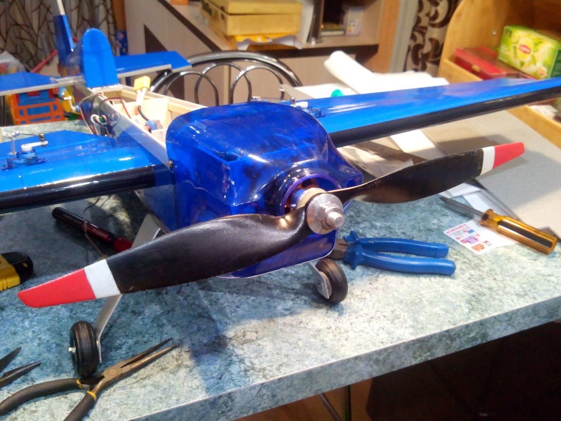
Install the motor.
We fasten the hood with small screws to the rails that go inside the fuselage.
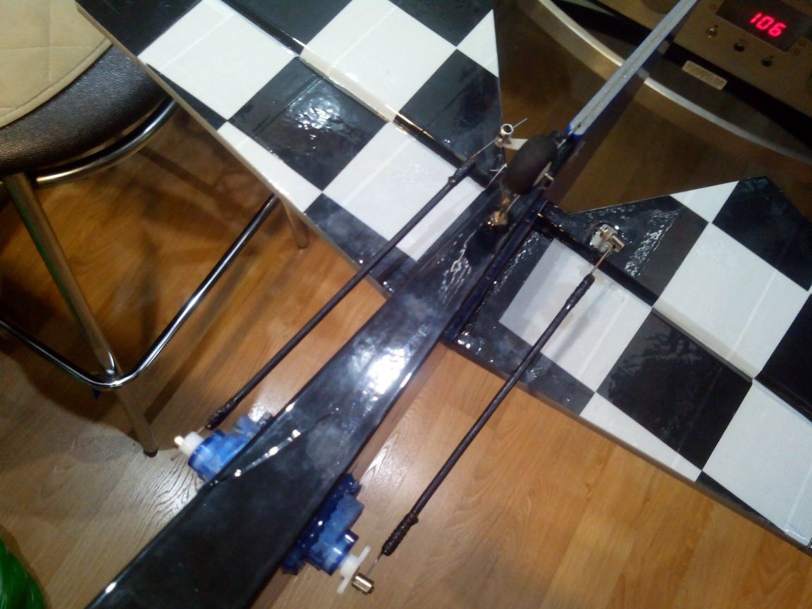
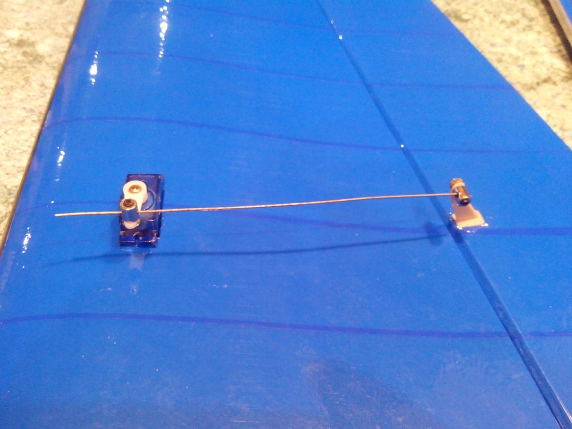
In the wing consoles, we make holes for the aileron servos.
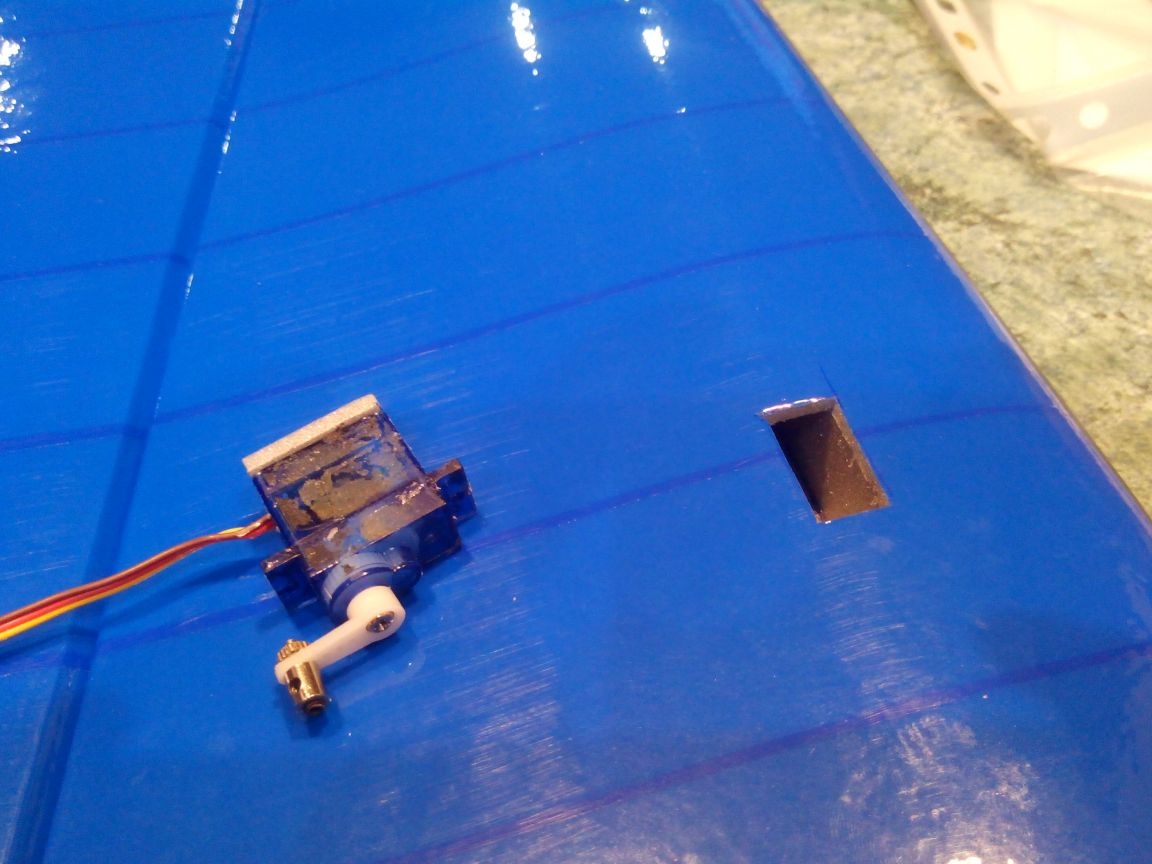
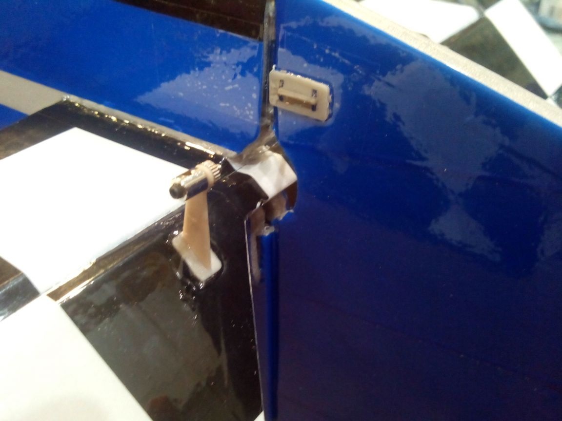
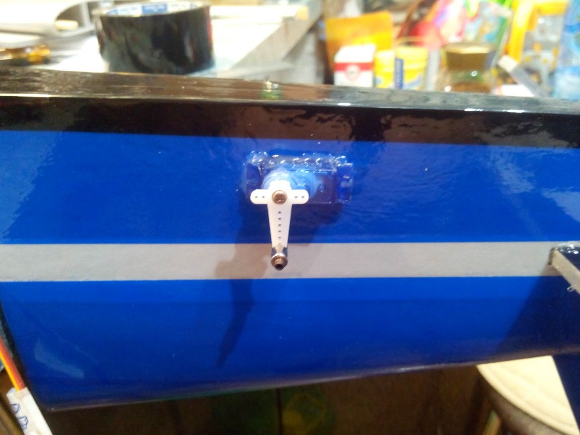
We glue the servos and boars into the wing.
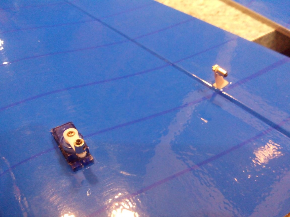
We install drafts of steel wire.
We fasten the screw.
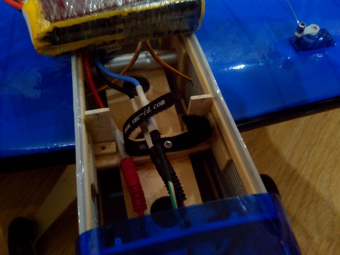
We put the rest of the electronics (regulator, receiver) into the fuselage.
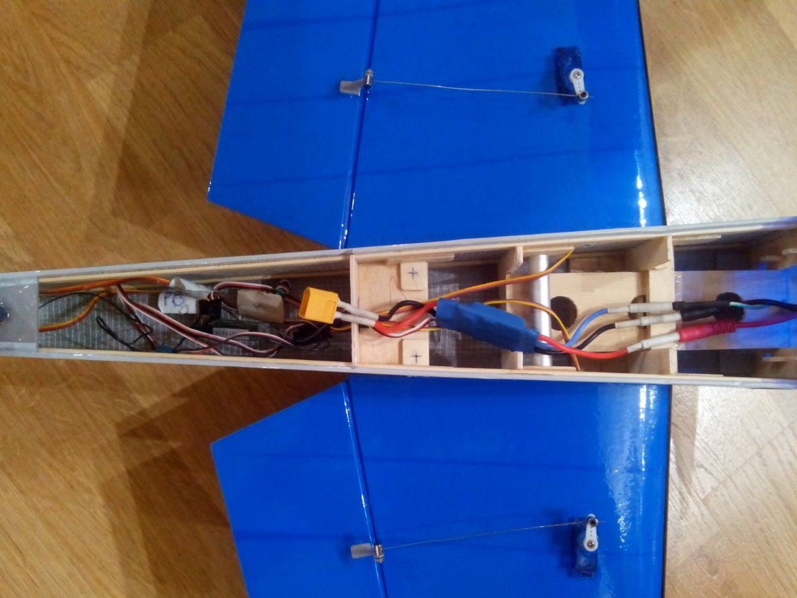
We fasten the Velcro tape with small screws to fix the battery inside the fuselage.
Close the lid. In front, the cover is fixed by the edge of the hood, on the back - on magnets.
Short video of flights:
Immediately, I note that the model came out very durable, this landing in a tree practically did not damage her.
Since the weather in the autumn is very capricious, the video turned out to be small, therefore I recommend watching a couple more videos with the same model, but shot a little earlier, that is, in the summer.