
Greetings the inhabitants of our site!
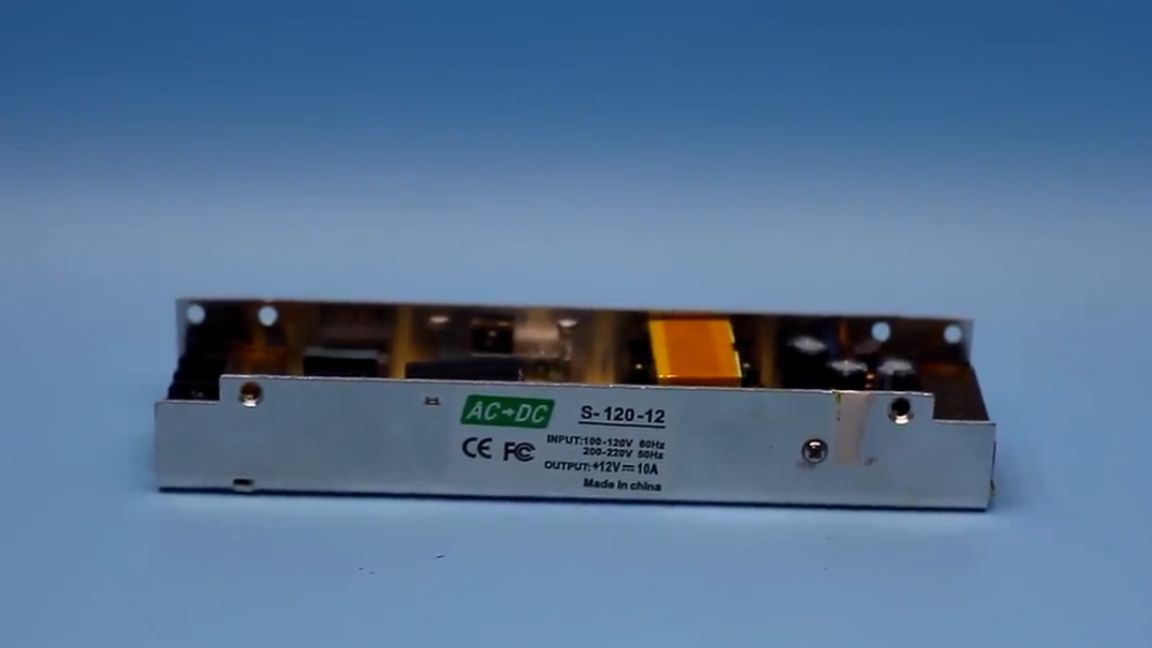
Probably, the problem we will talk about today is familiar to many. I think everyone had a need to increase the output current of the power supply. Let's look at a specific example, you have a 19-volt laptop power adapter that provides output current, well, suppose in the region of 5A, and you need a 12-volt power supply with a current of 8-10A. So the author (YouTube channel “AKA KASYAN”) once needed a power supply with a voltage of 5V and a current of 20A, and at hand there was a 12-volt power supply for LED strips with an output current of 10A. And so the author decided to redo it.
Yes, it’s certainly possible to assemble the required power source from scratch or use the 5-volt bus of any cheap computer power supply, but it will be useful for many electronic masters to know how to increase the output current (or in common people amperage) of almost any switching power supply.
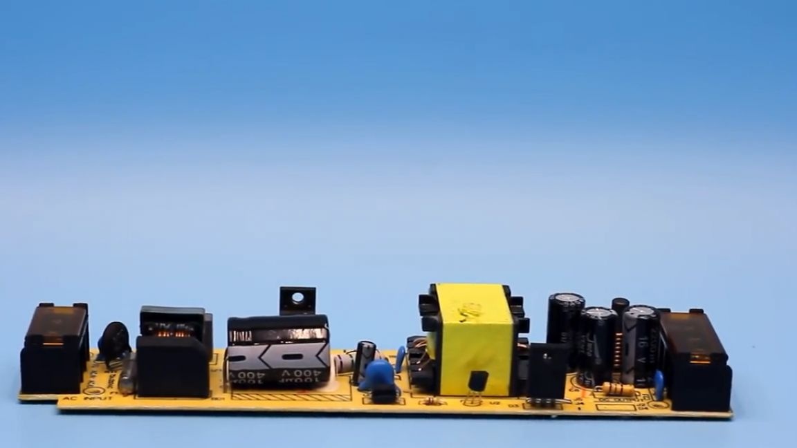
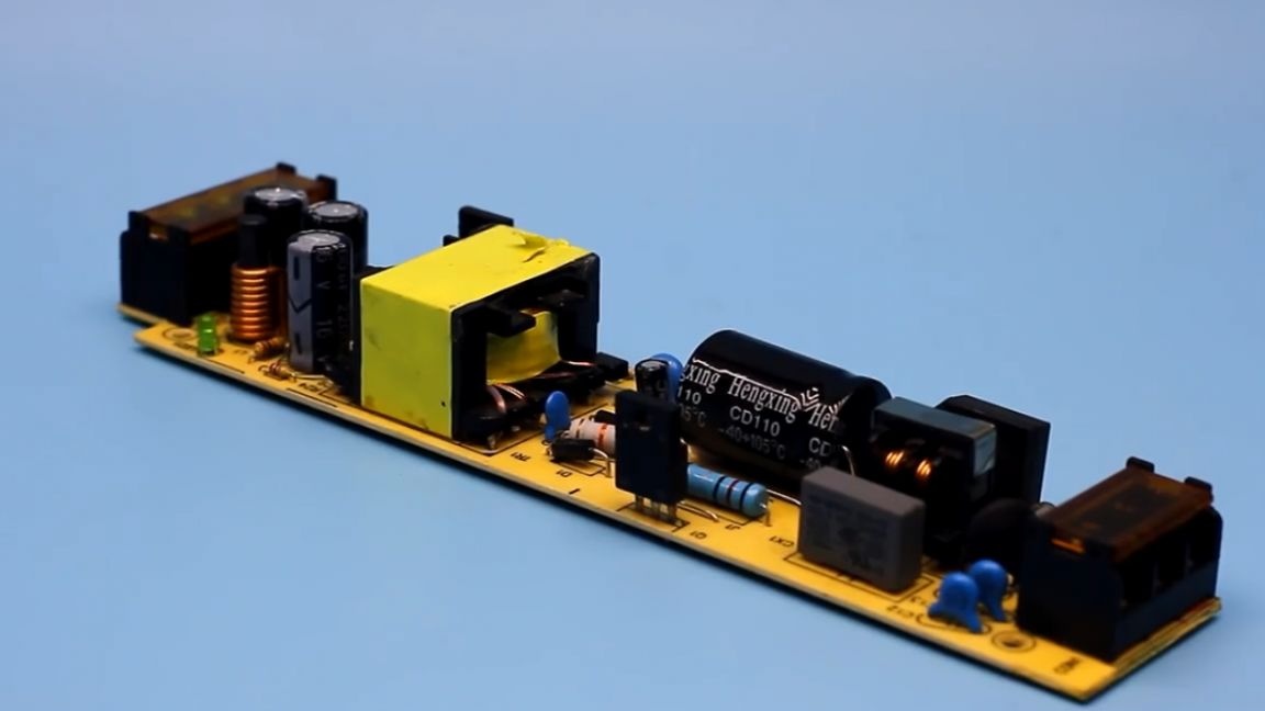
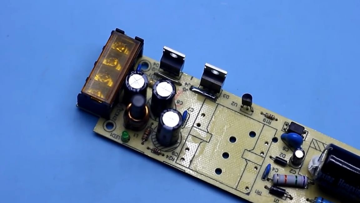
As a rule, power supplies for laptops, printers, all kinds of power adapters for monitors, and so on, are made according to single-cycle schemes, most often they are flyback and the construction is no different from each other. There may be a different configuration, a different PWM controller, but the circuitry is the same.
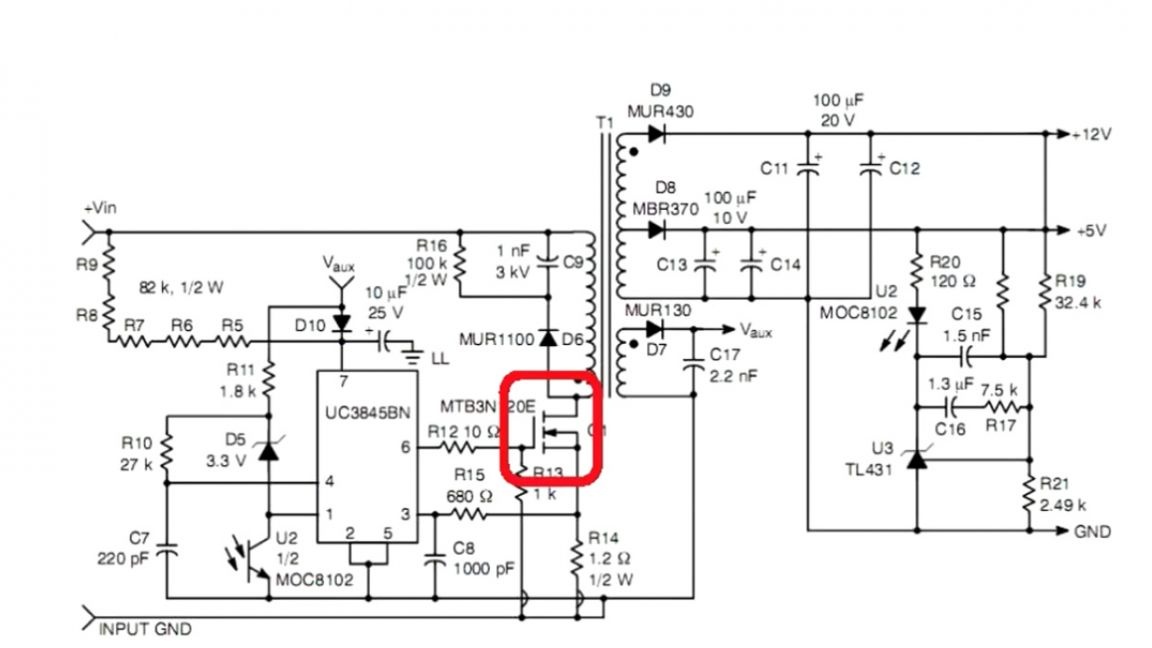
A single-cycle PWM controller is most often from the UC38 family, a high-voltage field-effect transistor that pumps the transformer, and the output is a half-wave rectifier in the form of a single or dual Schottky diode.
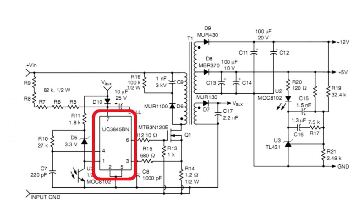
After it, a choke, storage capacitors, well, and a voltage feedback system.
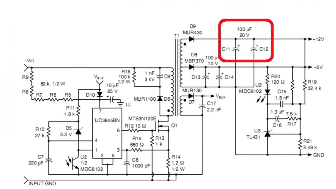
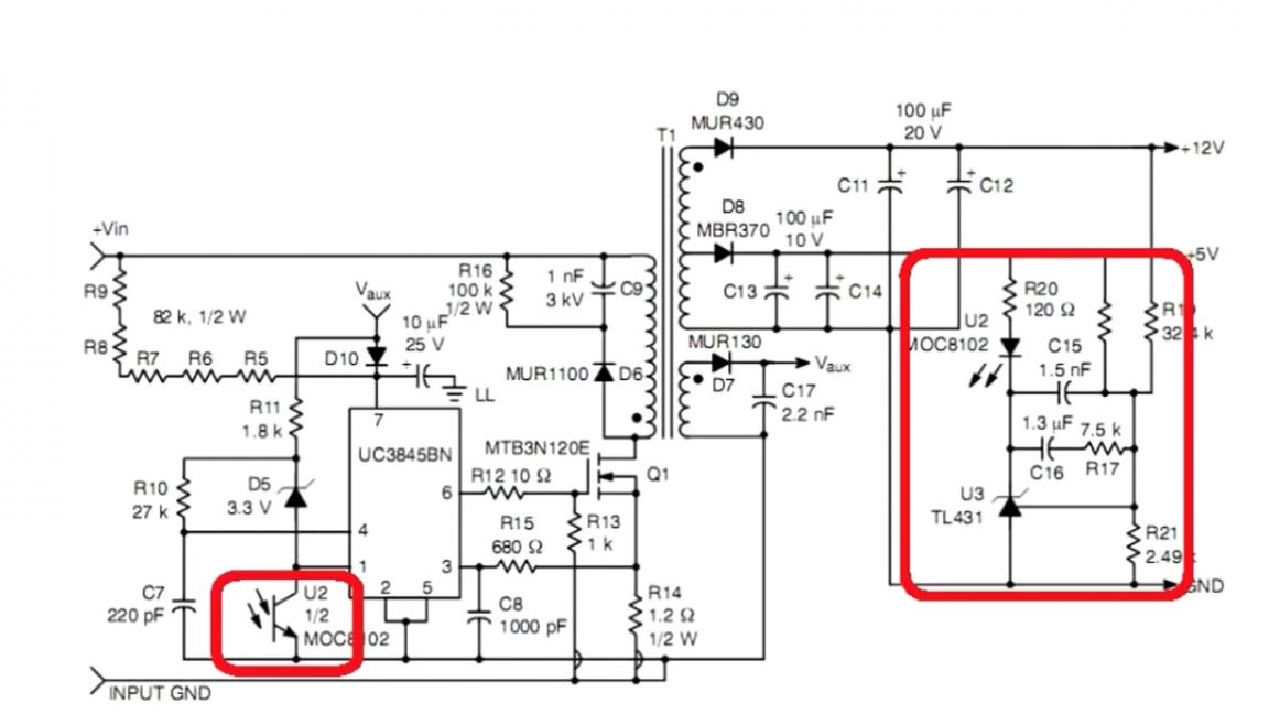
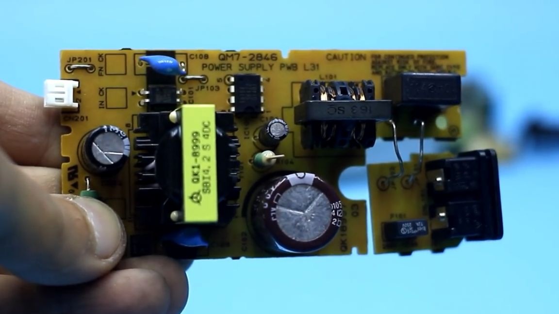
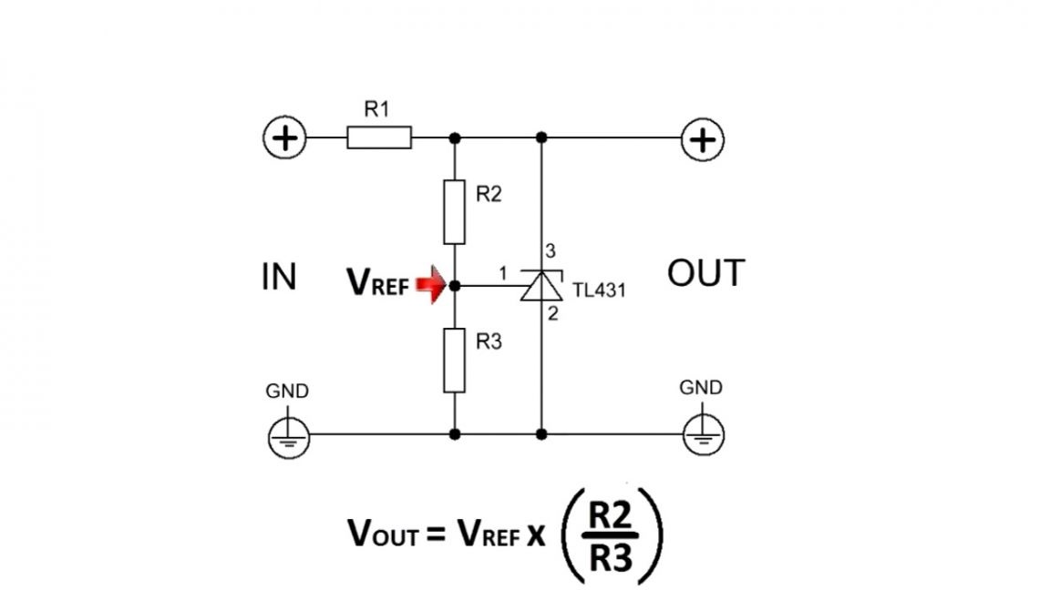
Thanks to the feedback, the output voltage is stabilized and strictly keeps within a given limit. Feedback is usually built on the basis of the optocoupler and the reference voltage source tl431.
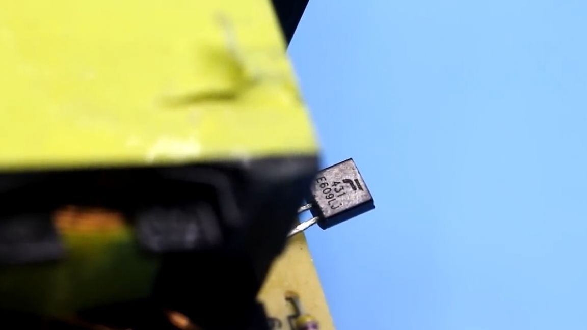
A change in the resistance of the resistors of the divider in its strapping leads to a change in the output voltage.
This was a general introduction, and now about what we have to do. It should be noted right away that we are not increasing capacity. This power supply has an output power of about 120W.
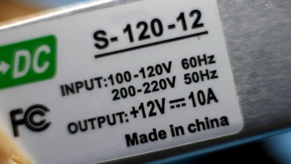
We are going to reduce the output voltage to 5V, but instead to increase the output current by 2 times. The voltage (5V) is multiplied by the current strength (20A) and as a result we get the estimated power of about 100W. We will not touch the input (high voltage) part of the power supply. All alterations will affect only the output part and the transformer itself.
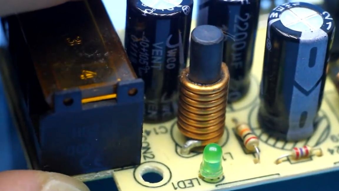
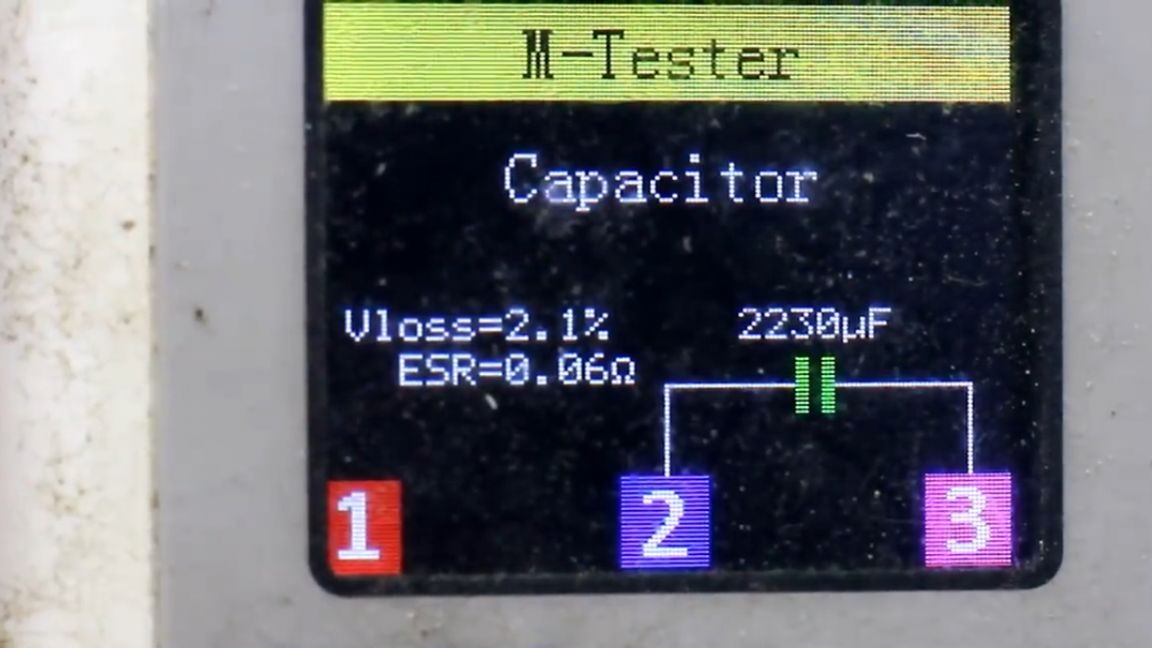
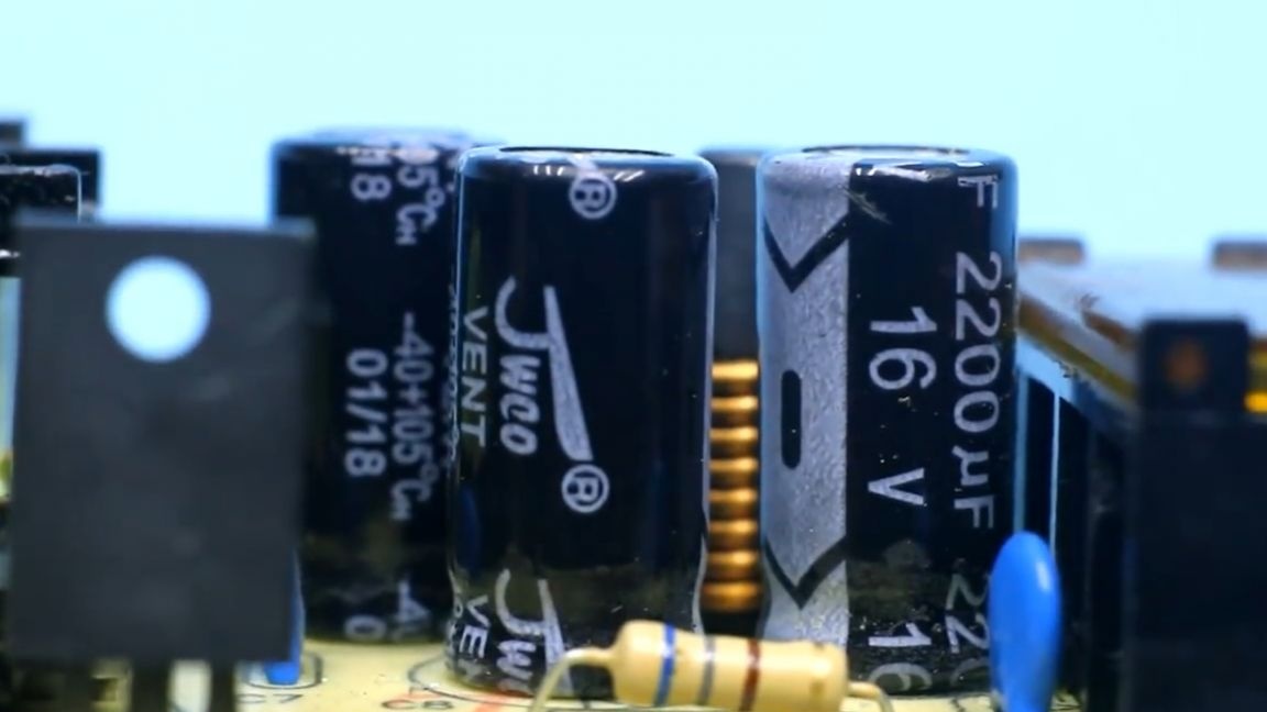
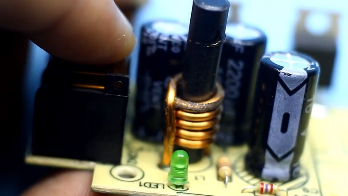
So let's get started.To begin with, the author decided to remove the electrolytic capacitors that stood at the output of the unit in order to replace them with a capacitor with low internal resistance.
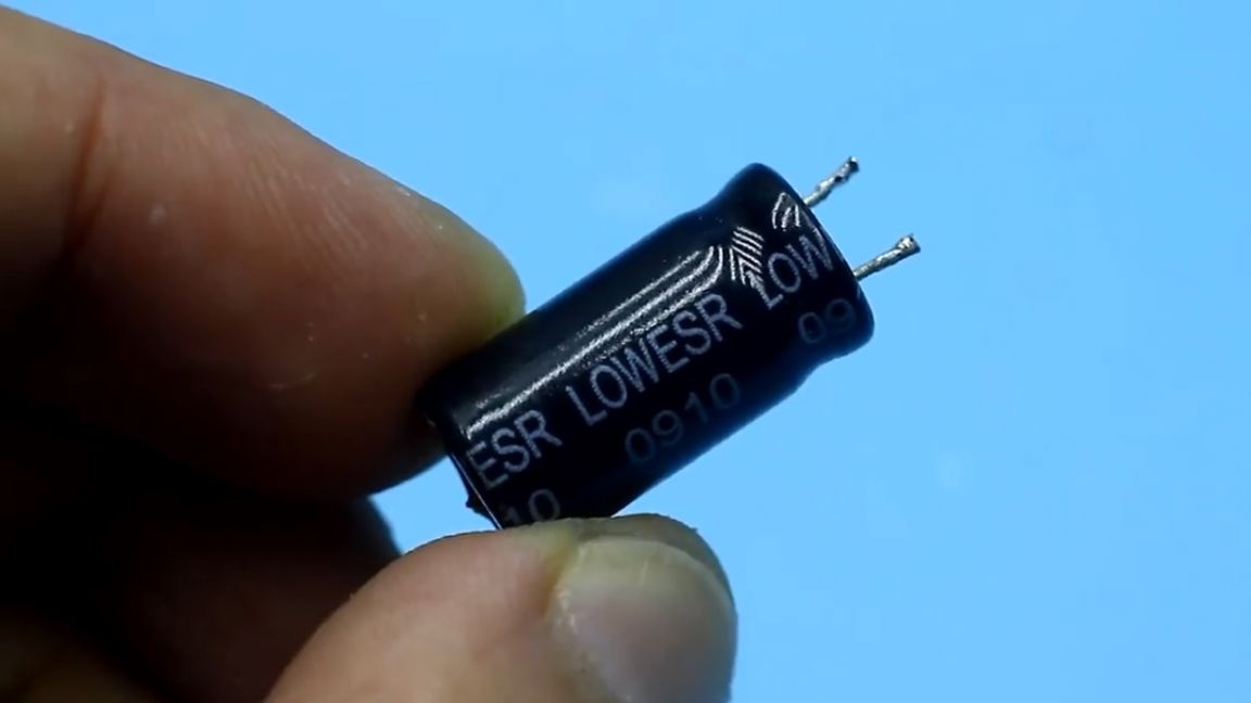
But later, after checking, it turned out that the native capacitors are also good and have a rather low internal resistance. Therefore, in the end, the author soldered them back.
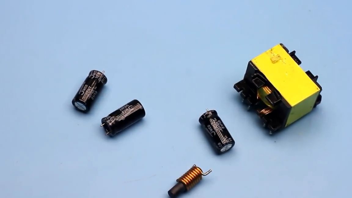
Next, solder the inductor, well, and a pulse transformer.
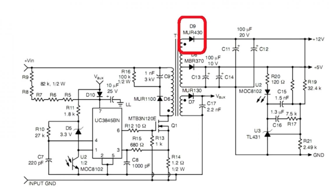
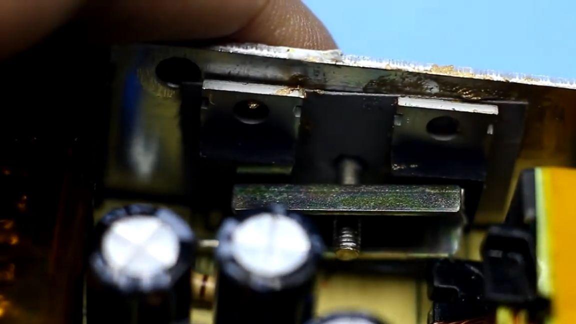
The diode rectifier is pretty good - 20 amperes. The best thing is that the board has a seat for the second diode of the same.
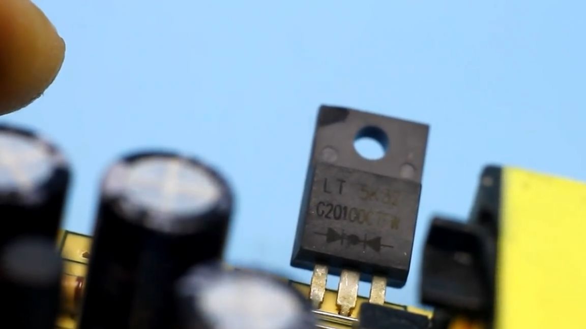
As a result, the author did not find the second such diode, but since recently he received exactly the same diodes from China only in a slightly different case, he inserted a couple of pieces into the board, added a jumper and strengthened the tracks.
As a result, we get a rectifier at 40A, that is, with a double current margin. The author put diodes on 200V, but this makes no sense, he just has a lot of them.
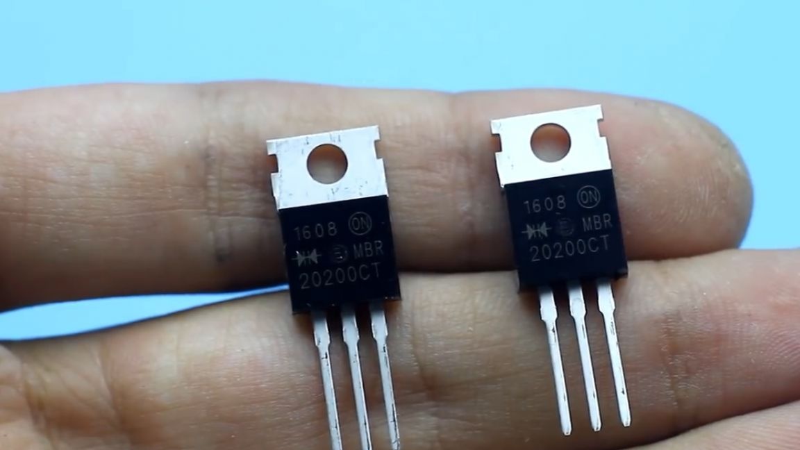
You can supply ordinary Schottky diode arrays from a computer power supply unit with a reverse voltage of 30-45V or less.
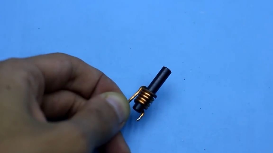
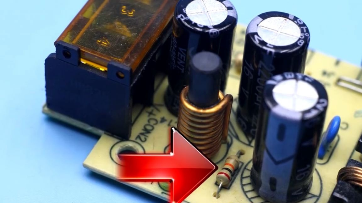
With the rectifier finished, move on. The inductor is wound like this wire.
We throw it out and take such a wire.
We wind about 5 turns. You can use a native ferrite rod, but the author had a thicker roll nearby, on which coils were wound. True, the rod turned out to be slightly long, but later we will break off all the excess.
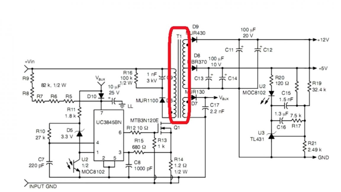
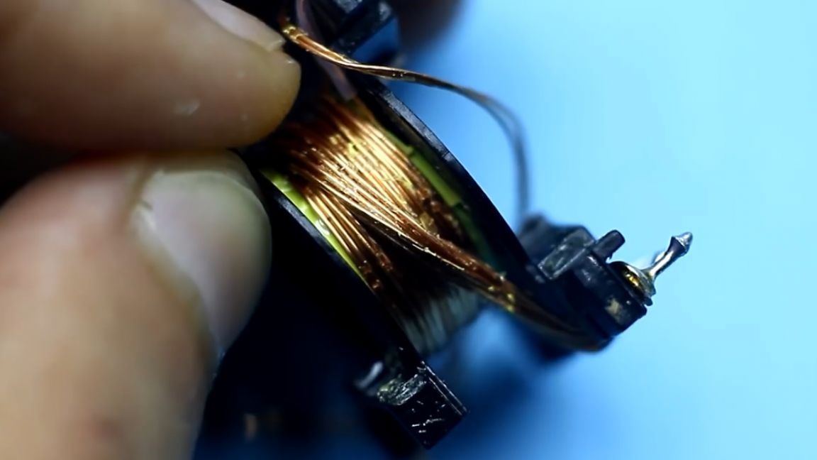
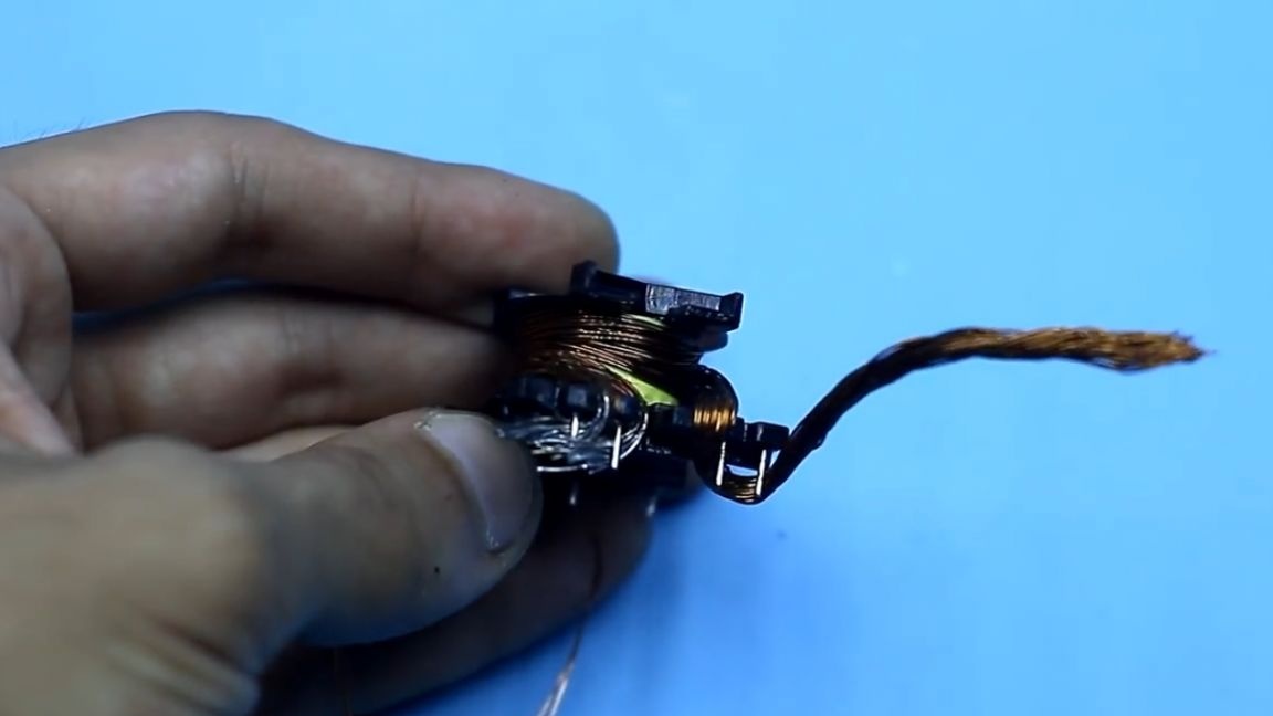
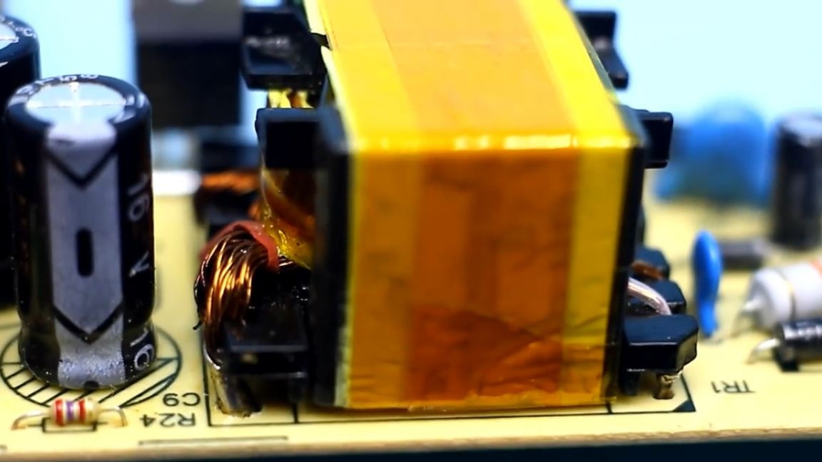
The transformer is the most important and crucial part. We remove the tape, warm the core with a soldering iron on all sides for 15-20 minutes to loosen the glue and carefully remove the halves of the core.
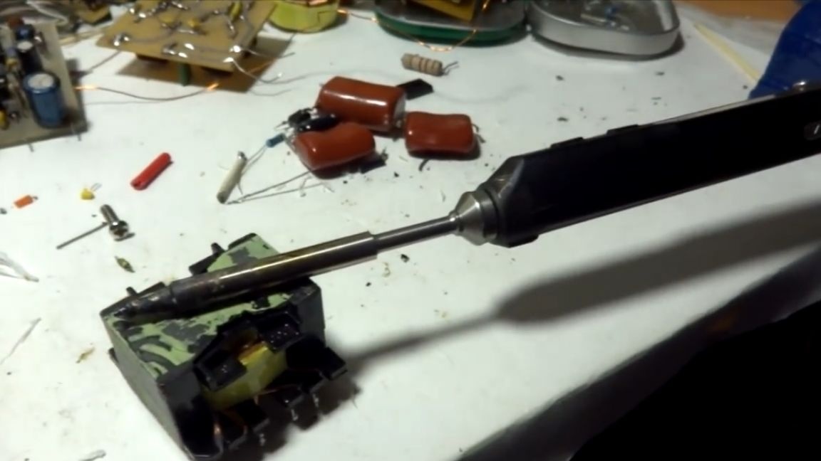
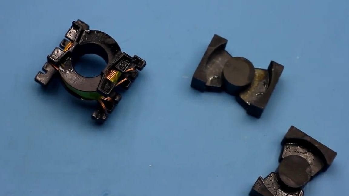
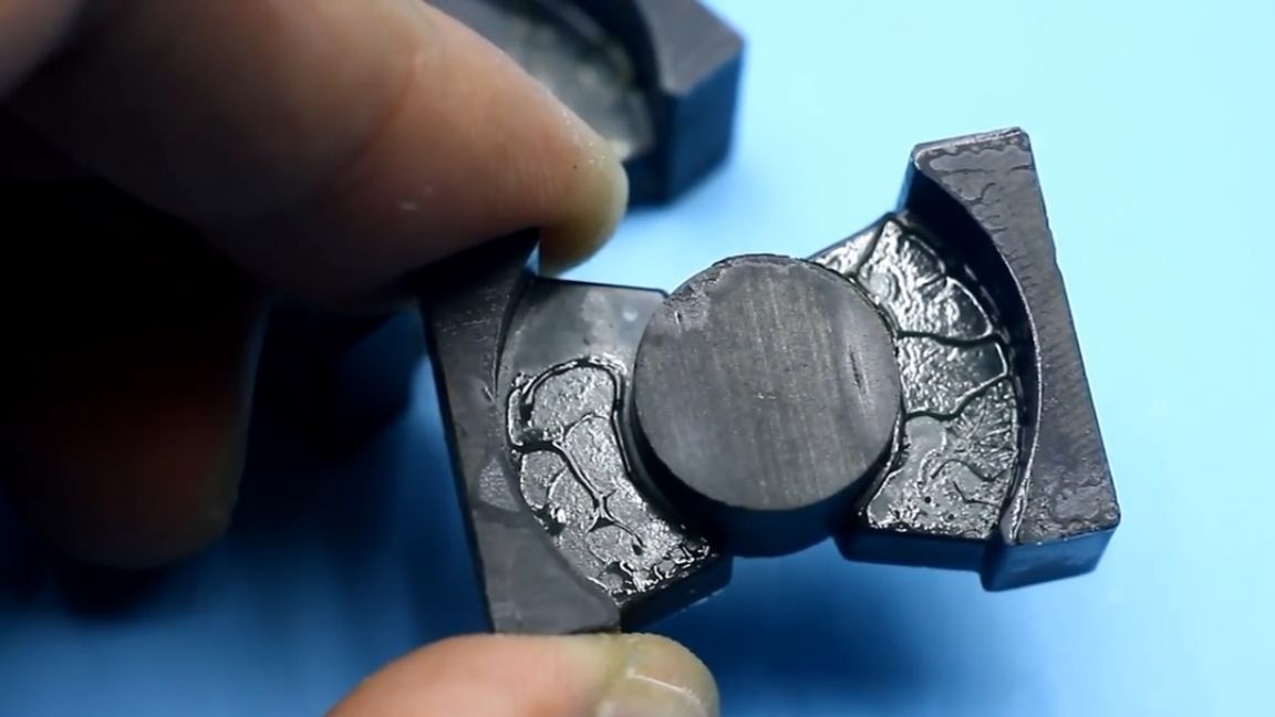
Leave the whole thing for about ten minutes to cool. Next, remove the yellow tape and unwind the first winding, remembering the direction of winding (well, or just take a couple of pictures before disassembling, in which case they will help you). The second end of the wire is left on the pin. Next, unwind the second winding. Also, the second end is not soldered.
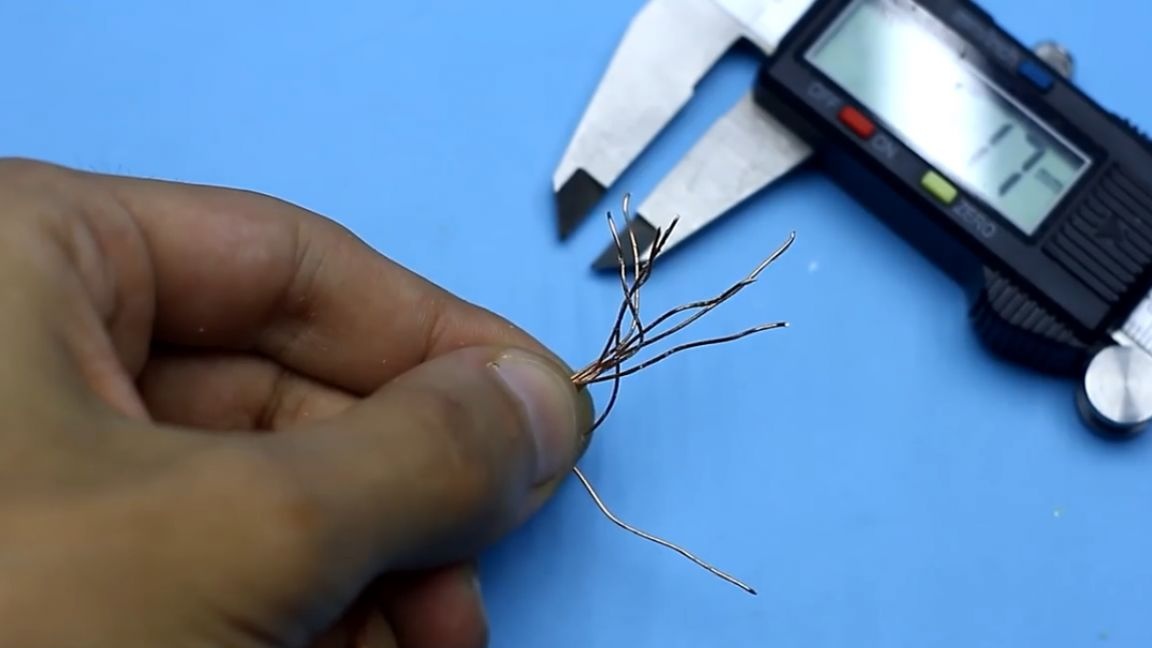
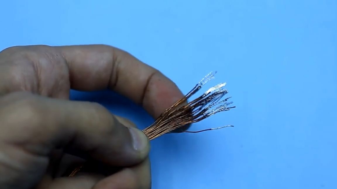
After that, before us is the secondary (or power) winding of our own person, which is exactly what we were looking for. This winding is completely removed.
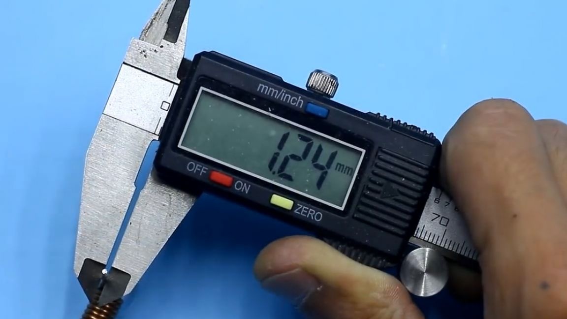
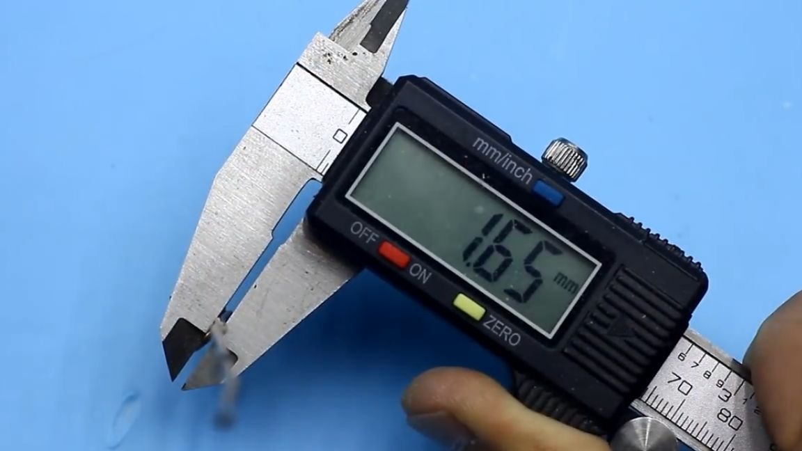
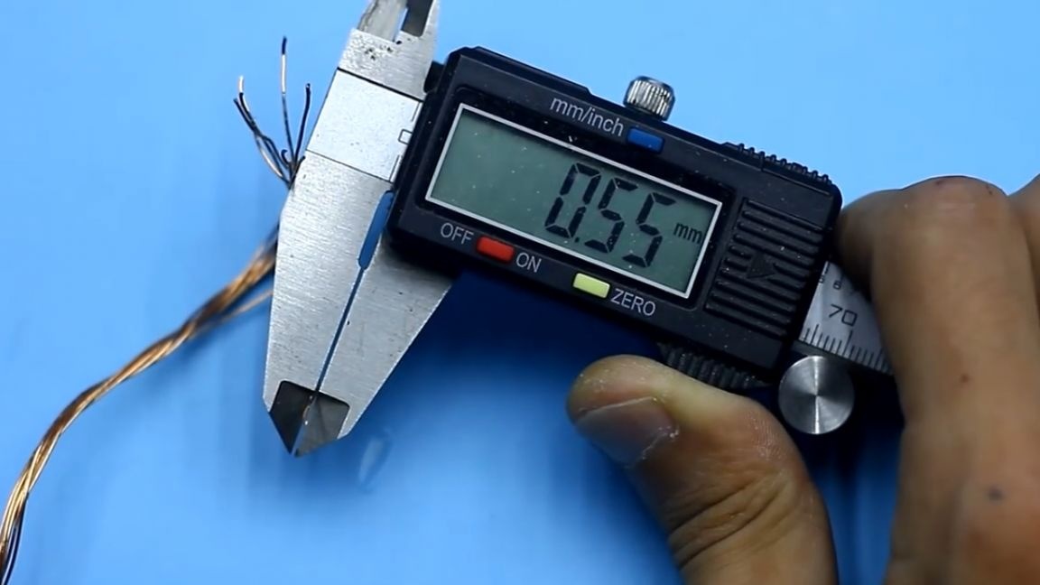
It consists of 4 turns, wound with a bundle of 8 wires, each 0.55 mm in diameter.
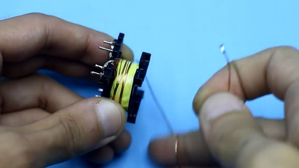
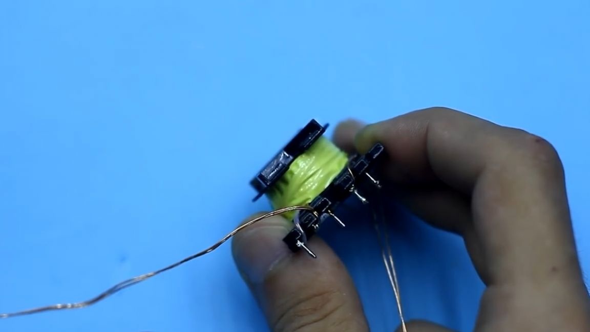
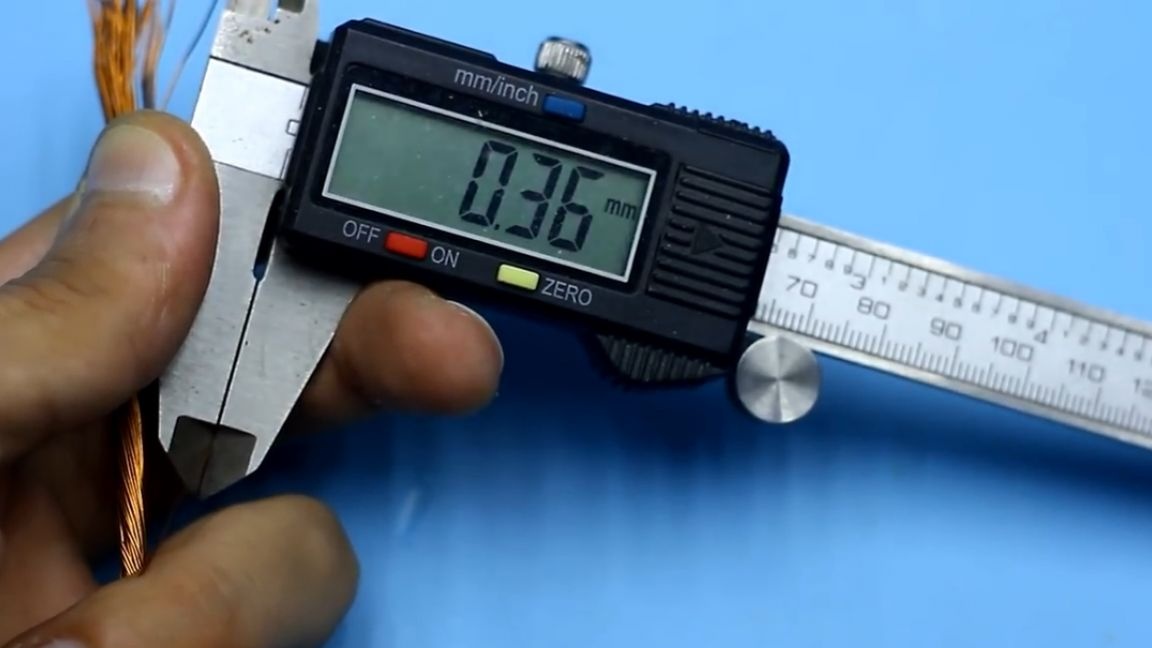
The new secondary winding that we wind up contains only one and a half turns, since we need only 5V of the output voltage. We will wind in the same way, take a wire with a diameter of 0.35 mm, but here the number of wires is already 40 pieces.
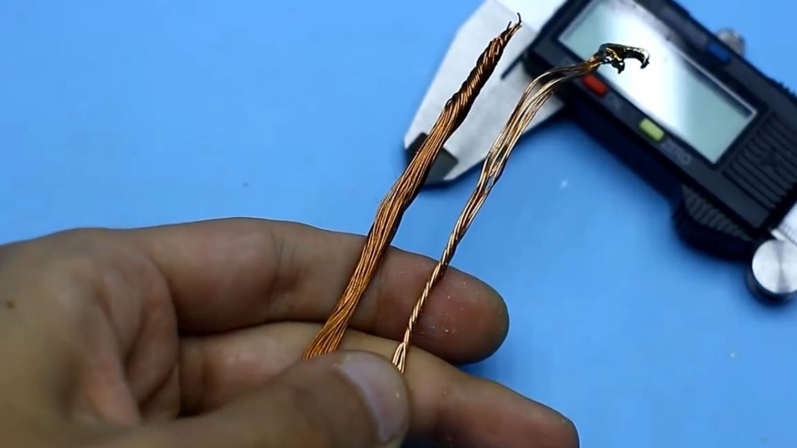
This is much more than necessary, well, however, you yourself can compare with the factory winding. Now we wind all the windings in the same order. Be sure to follow the direction of winding all the windings, otherwise nothing will work.
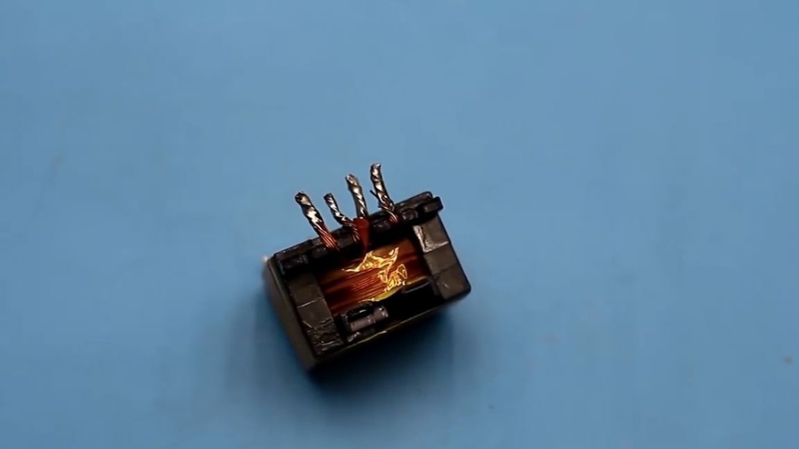
The veins of the secondary winding are preferably tinned before the start of winding. For convenience, we break each end of the winding into 2 groups so that giant holes for installation are not drilled on the board.
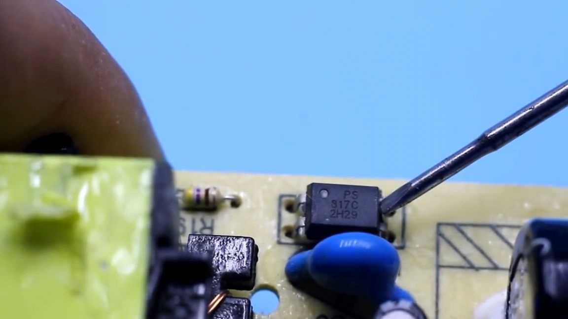
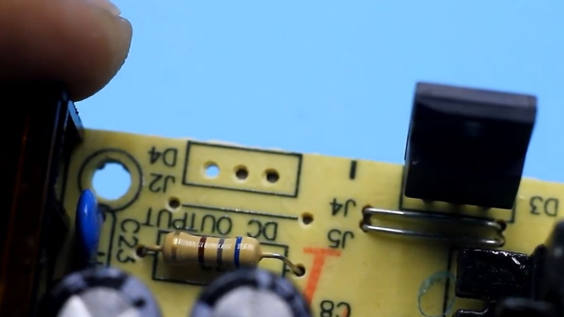
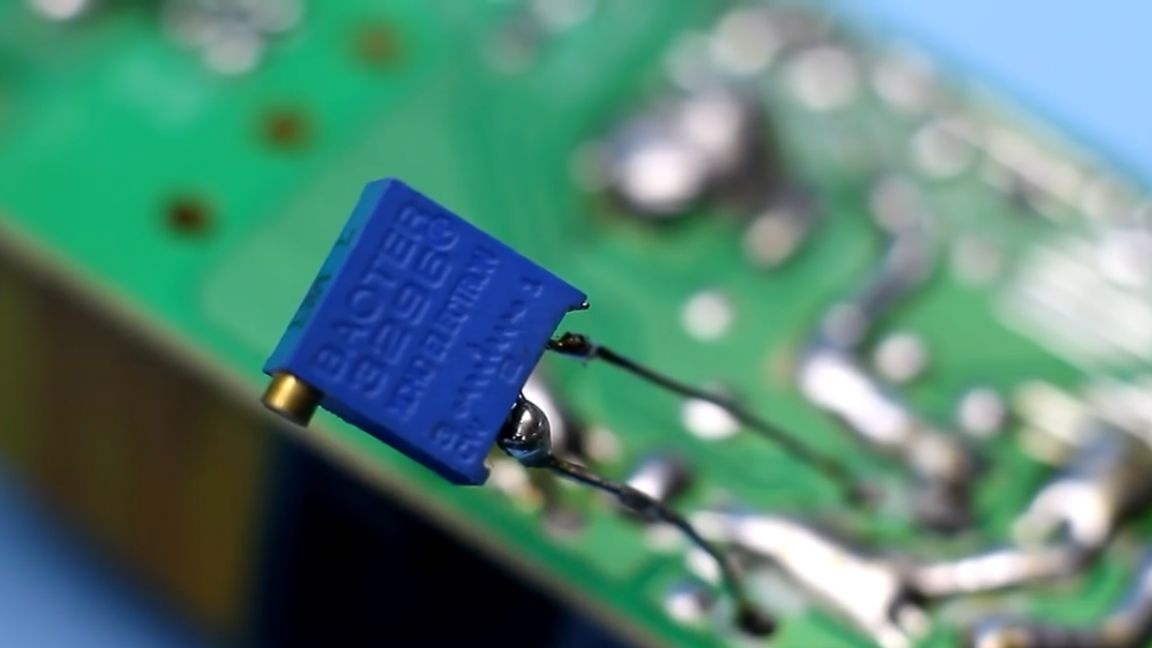
After the transformer is installed, we find the tl431 chip. As previously mentioned, it is she who sets the output voltage.
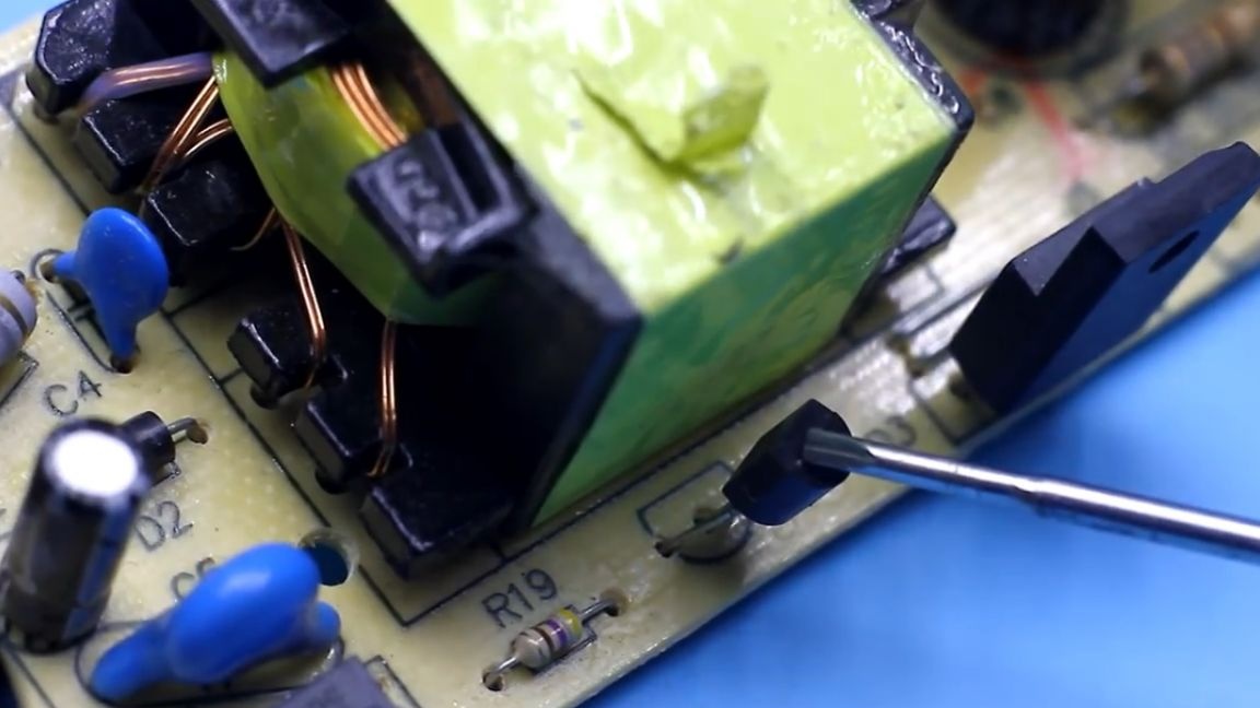
In its harness we find the divisor. In this case, 1 of the resistors of this divider is a pair of smd resistors connected in series.
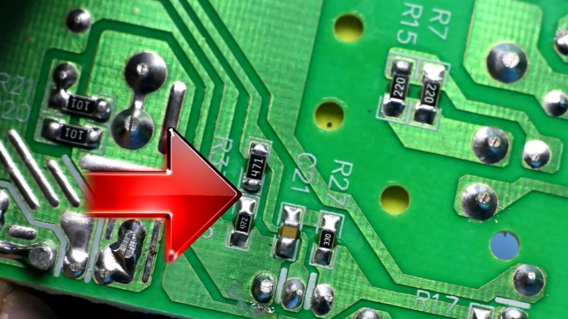
The second divider resistor is brought closer to the output. In this case, its resistance is 20 kOhm.
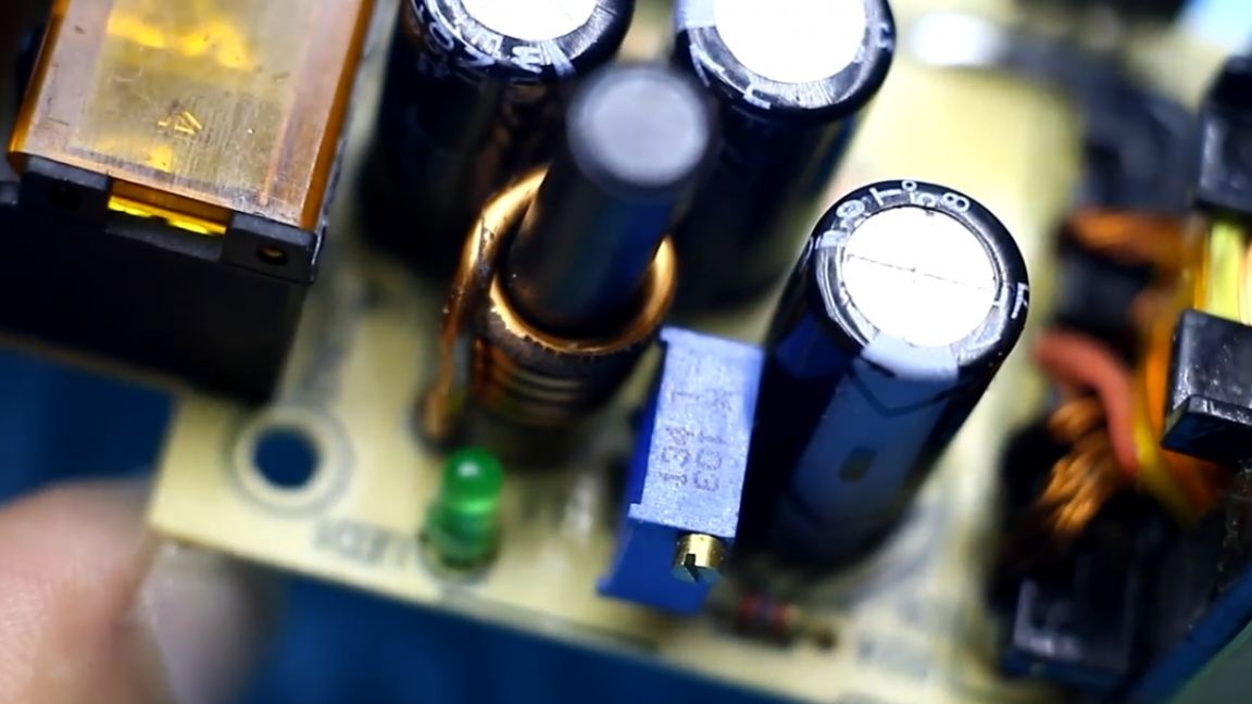
We solder this resistor and replace it with a trimmer of 10 kOhm.
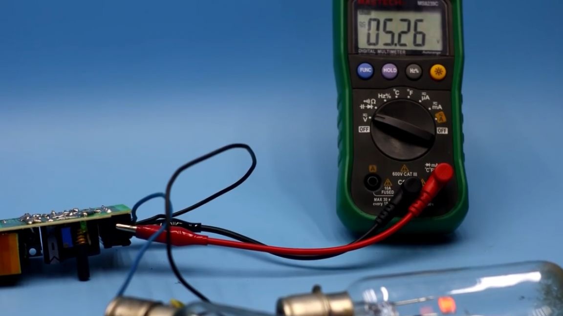
We connect the power supply to the network (required through a safety net incandescent lamp with a power of 40-60W). We connect a multimeter to the output of the power supply and preferably not a big load. In this case, these are low-power 28V incandescent lamps. Then, very carefully, without touching the board, we rotate the tuning resistor until the desired output voltage is obtained.
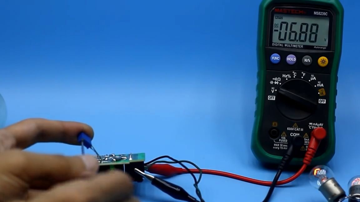
Then we cut everything down, wait 5 minutes, so that the high-voltage capacitor on the block is completely discharged. Then we solder the tuning resistor and measure its resistance. Then we replace it with a constant, or leave it. In this case, we also have the ability to adjust the output.
After all this, lightly load the board first with a car halogen, and then with hellish lamps from a movie projector.
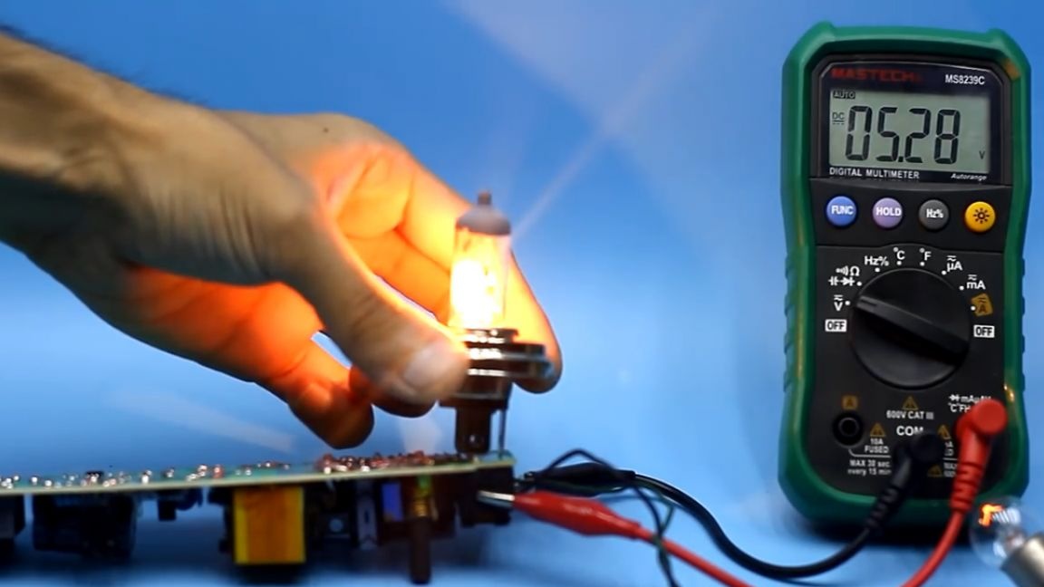
This is in order to understand how well the feedback works. And as you can see, the output voltage holds well. After you need to strengthen the tracks on the secondary circuit.It is also advisable to reinforce them with a wire, the currents here will be already 2 times more than before.
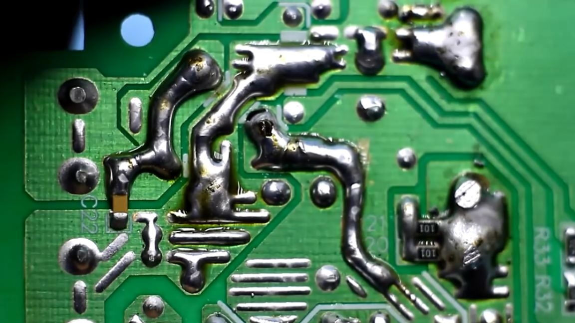
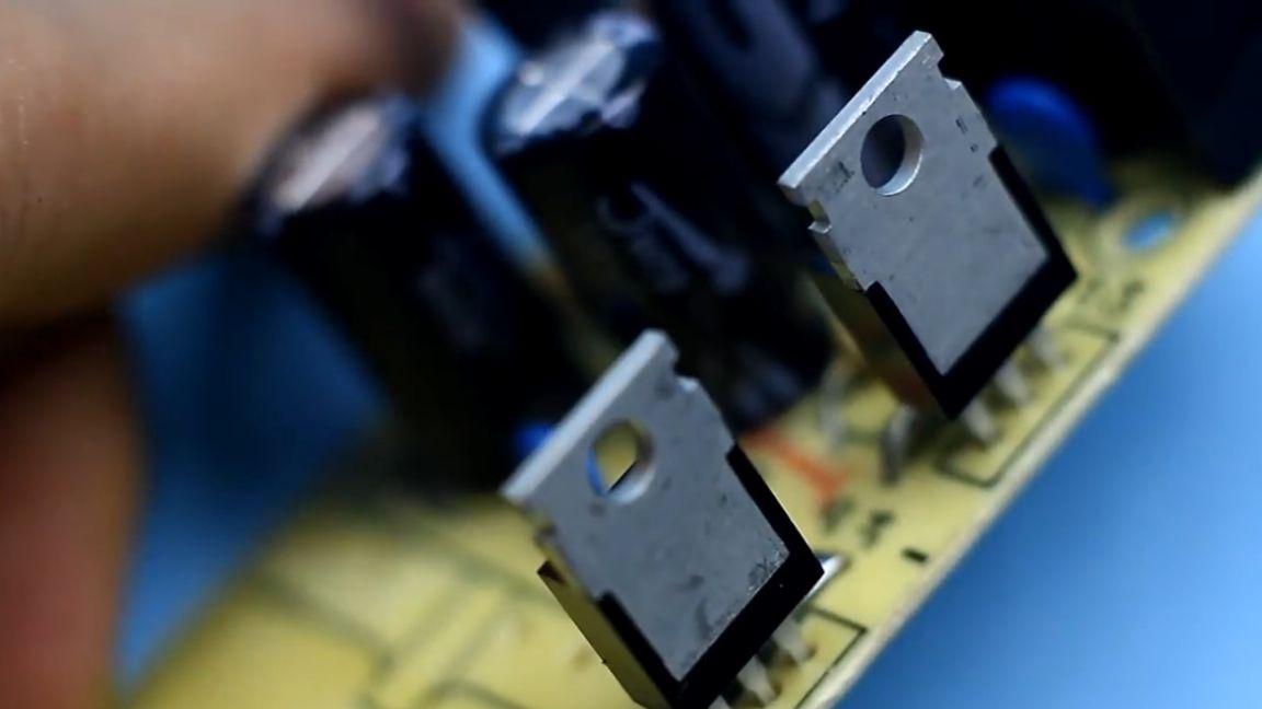
Before we put everything back together, we additionally solder the board (although the soldering here from the factory was pretty good). We apply thermal grease to the power transistor and rectifier diodes. By the way, if the diodes are such as those of the author, then they must be isolated from the housing with a heat-conducting gasket.
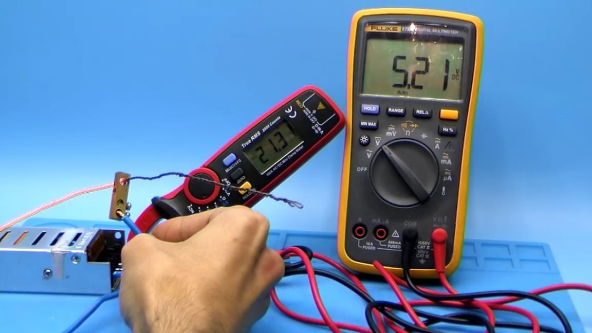
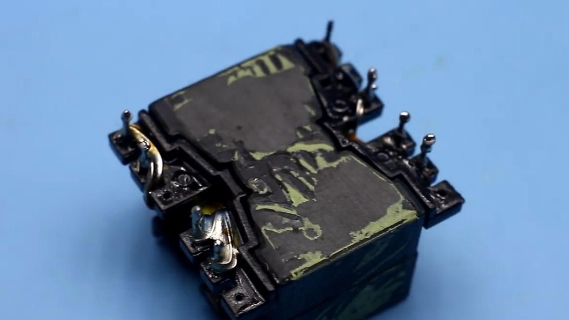
And here is the board in the case. Now it's time to test the block. For this, the author made a load of nichrome, which is able to squeeze a current of 20 amperes or more from the power supply.
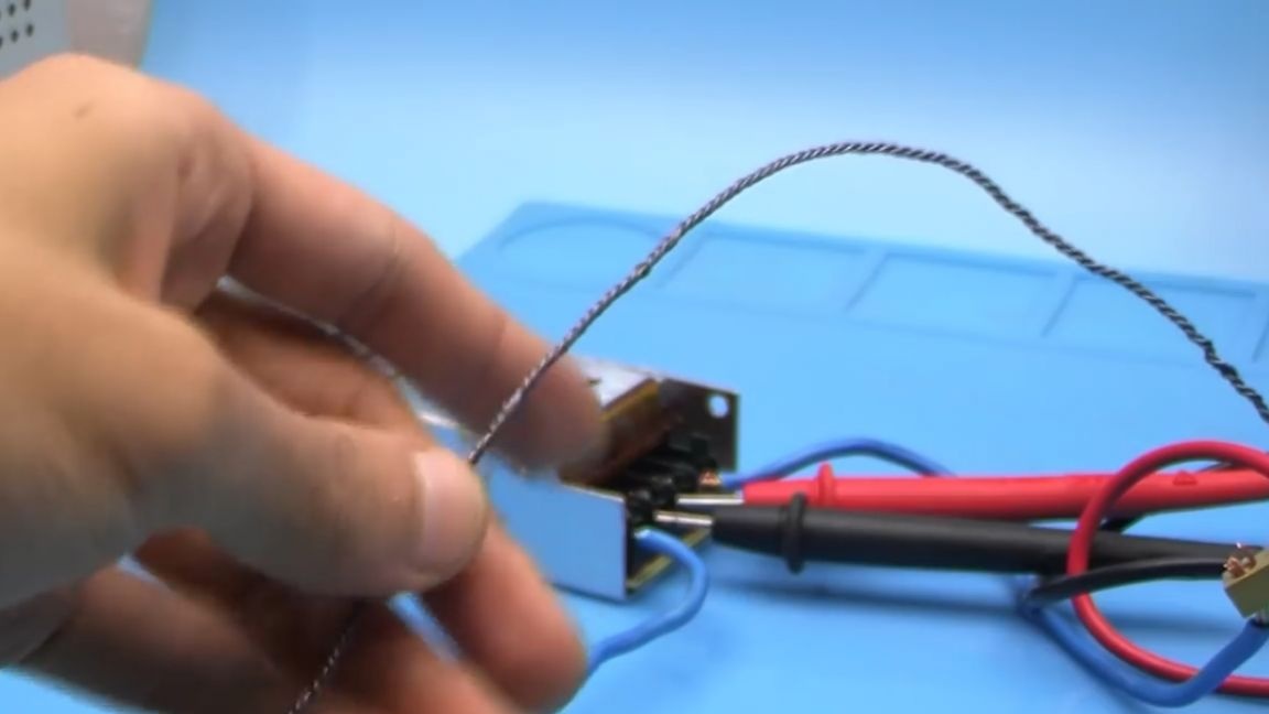
Current clamps will show us the current value of the current output, and the multimeter output voltage.
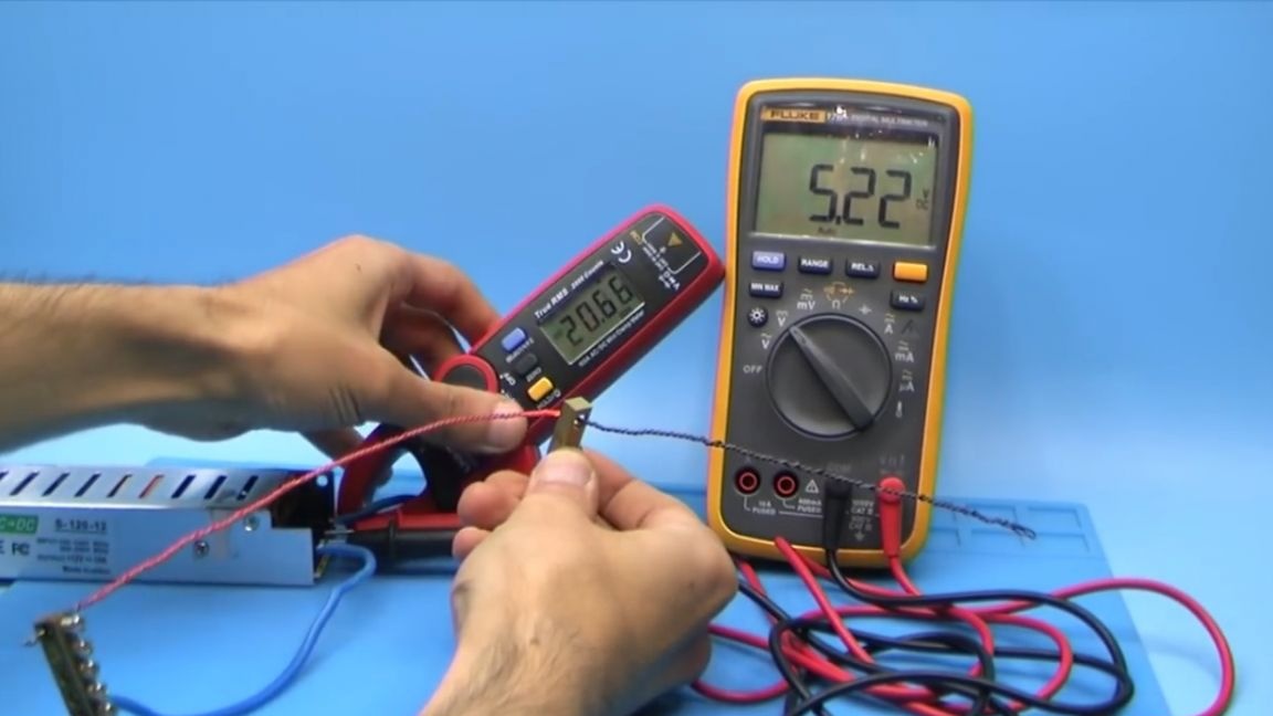
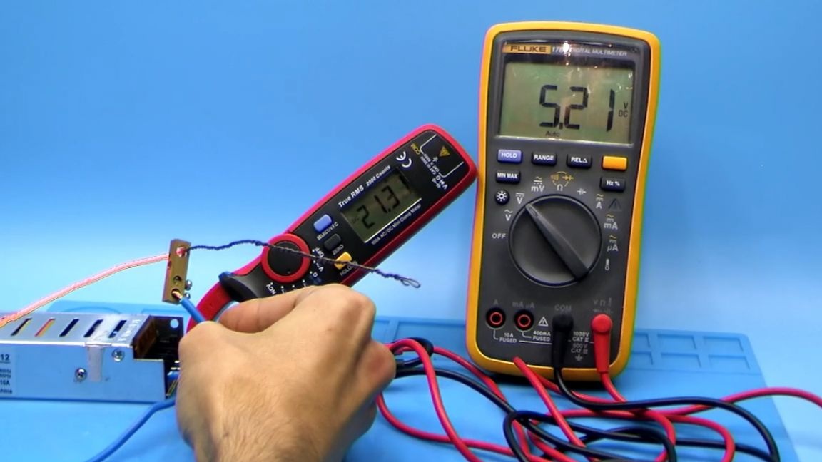
We just removed a current of more than 20A from the unit, without a drop in the output voltage. During the off-screen measurements, there was even 24A, while trying to remove more, the protection worked, that is, we can safely say that our alteration was successful.
That's all. Thank you for attention. See you soon!
Video: