

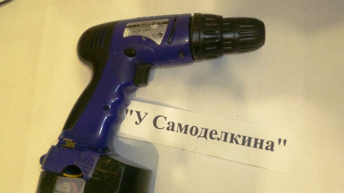
You can, in principle, buy a new Shurik with lithium-ion batteries, but having two screwdrivers with a still normal mechanical part, it was decided to reconstruct the power tool. Particularly interesting to try to do it all. do it yourself.
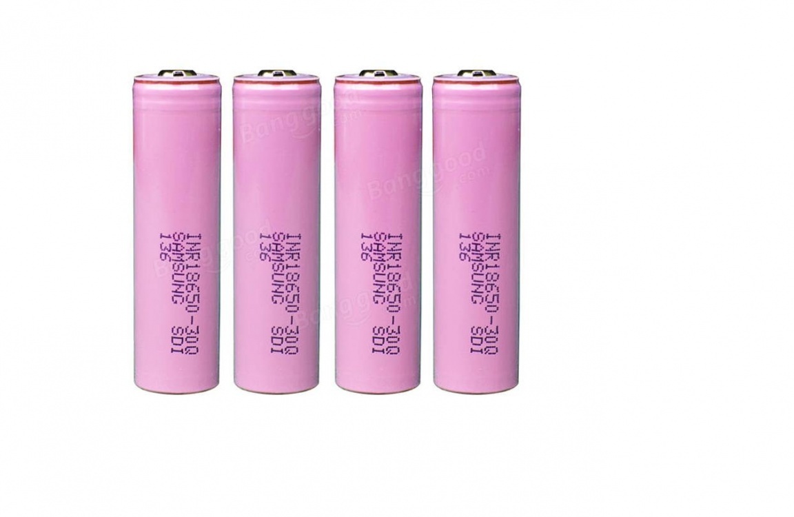
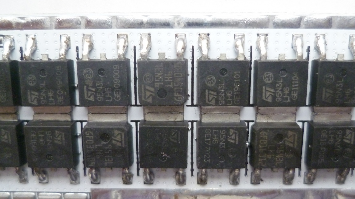
Having studied the issue of reworking lithium on the network, I ordered components from the Chinese. The main components in that alteration are high-quality high-current lithium-ion batteries of the 18650 format and a reliable BMS board with balancing the elements of the battery assembly. I measured the working current of my screwdriver and it was 10-15A. I chose type batteries and a charge and discharge protection and control board with balancing.
Enumeration of tools and materials.
- 4pcs lithium-ion battery;
- control board, protection with balancing -1pcs;
- connecting wires 1.5 sq. mm;
- soldering iron;
- tester;
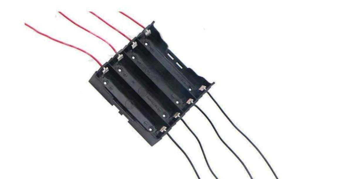
- a plastic box for batteries or a finished holder-1pc;
- (charge indicator 3s / 4s / 5s) -1pcs;
- power switch for a voltmeter (or button) -1pcs;
- -1 PC;
- A standard screwdriver charger (or power source).
Step one. Assembly of the battery compartment screwdriver.
Wiring diagram
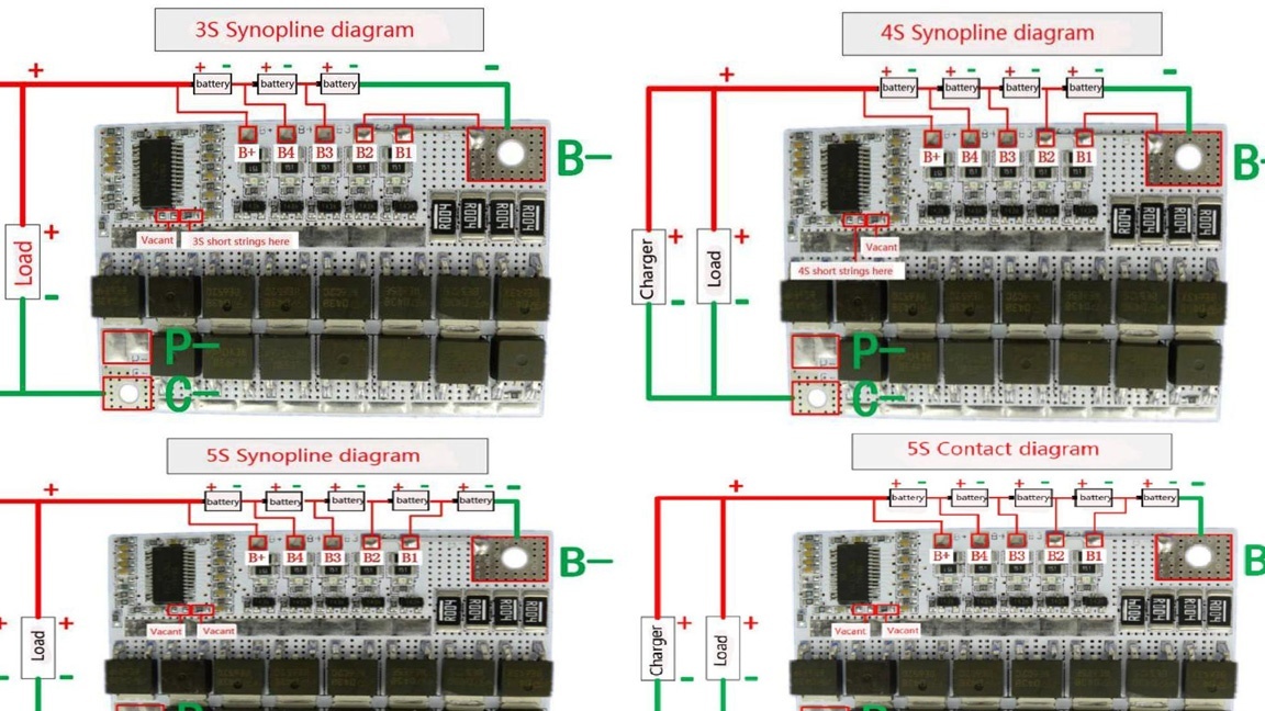
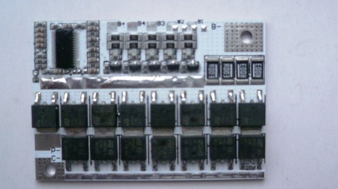
I used the universal BMS board, that is, you can turn it on for three, four or five batteries (12V, 16.8V or 18V). It remains to choose the connection scheme in accordance with your screwdriver.
Jumper Place
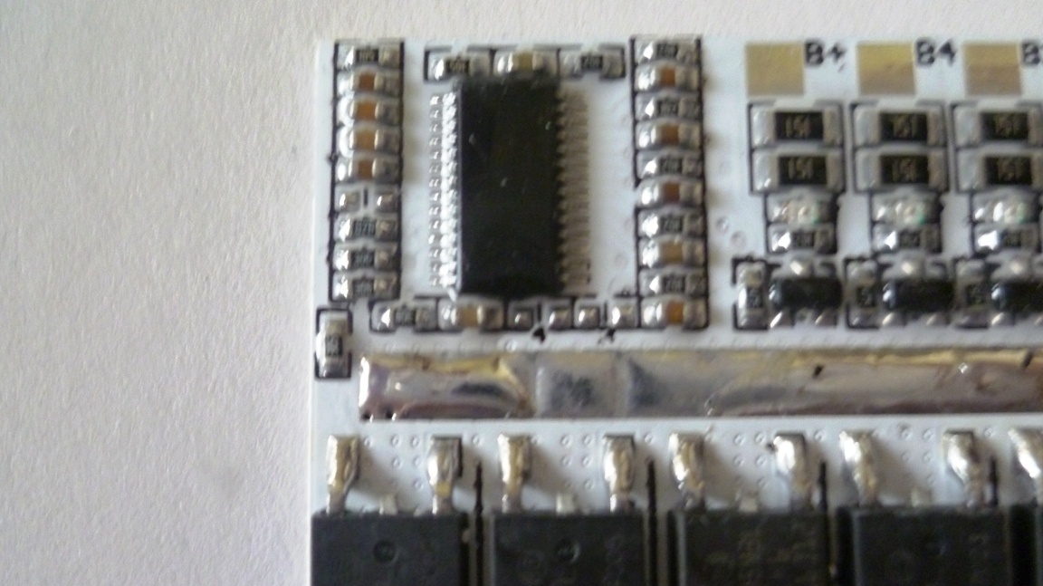
The microcircuit has jumper sealing spots marked with numbers 4 and 3. We don’t install jumpers according to 5S scheme. According to the 4S scheme, we solder the jumper between contacts 4, well, according to the 3S scheme, we solder between the contacts 3. The most convenient scheme is with a common negative wire to power the screwdriver motor and charge the batteries. The total minus is connected to the site FROM-.
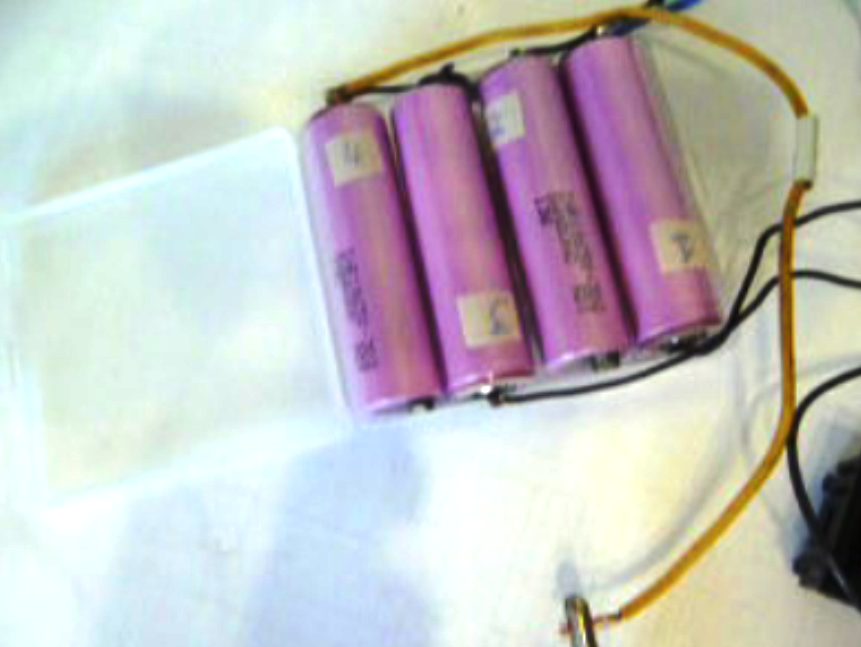
The lithium-ion battery 18650 was mounted in a plastic box with jumpers (it was bundled with batteries), to which balancing control wires were also soldered. You can connect the batteries to each other by soldering, but you need to quickly solder the wires eliminating overheating of the battery case. You can use spot welding or you can use a ready-made holder. It is better to make power conclusions from a flexible copper wire with a cross section of 1.5-2.5 square mm, since the currents to the screwdriver motor are rather large.
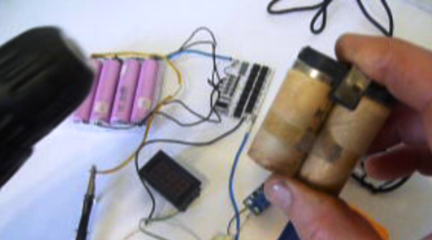
After assembling the entire circuit, it remains to solder the two power wires to the terminals of the battery compartment. I used two old nickel-cadmium batteries with a terminal block. The positive wire was soldered to the plus of the battery and the negative to the metal case of another battery. As a result, this design tightly entered its regular place.
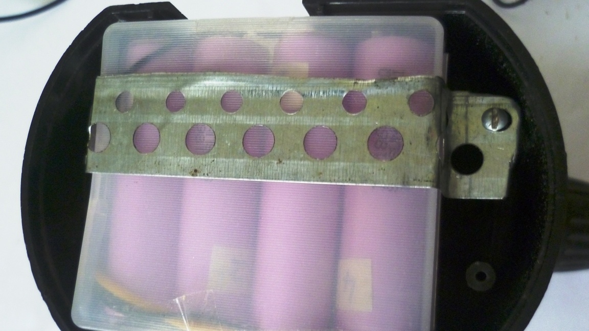
The BMS controller board was glued with double-sided tape to the plastic battery box. This whole structure fit tightly into the body of the old battery compartment. In order not to fall out, I secured it with a metal strip. The bottom cover of the battery compartment has been lost for a long time, later it will be necessary to make a homemade one.
Step Two Checking the operation of the BMS board when charging 18650 batteries.
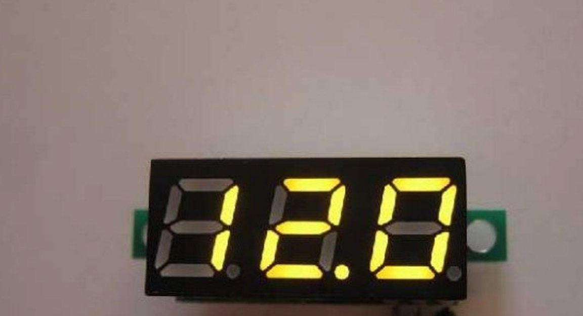
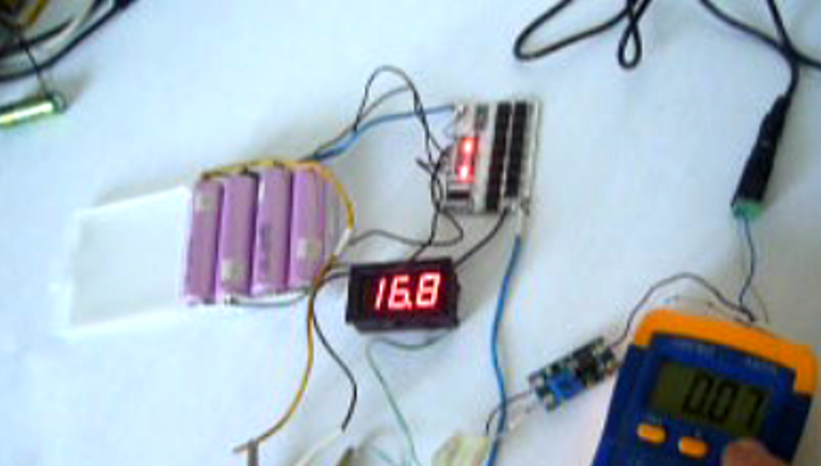
Before installing the BMS board and batteries in the standard compartment, I charged the entire circuit. Power for 12.6 V (3S) screwdrivers can also be supplied from the 12V \ 3A adapter. After the power source, it is best to turn on the charge board. This will give a stabilized voltage (in my case 16.8V) and limit the battery charge current.
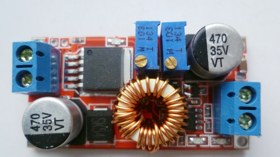
To do this, we set the voltage regulator at 16.8V at idle and the desired charging current of -1.5A with the current regulator. For lithium-ion batteries of other brands, we set according to the datasheet.
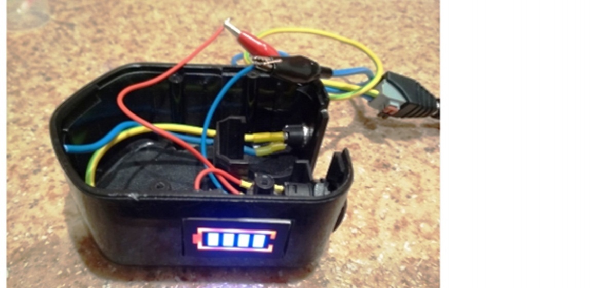
You can install this board in a regular charger screwdriver. To control the degree of charge of the batteries, you can install a mini-voltmeter or a charge indicator in the battery compartment. So that there is no unnecessary current consumption from his side, you can turn it on through a switch or button. The charge indicator is available in 3s / 4s / 5s.
The BMS controller board at the end of charging balances all the elements of the battery so that all cells charge the same. The cell that has gained full charge is bypassed by the circuit (the corresponding LED will light up).
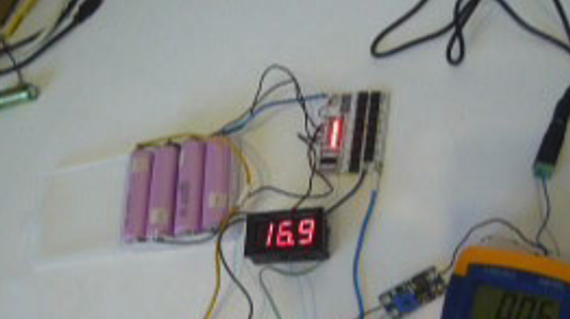
Charging energy goes to the elements having a lower voltage. Already charged cells will receive less current than undercharged ones (balancing current -60mA). This process will take place until all the battery cells have a predetermined voltage level.
At the end of balancing, all the LEDs on the board will light.
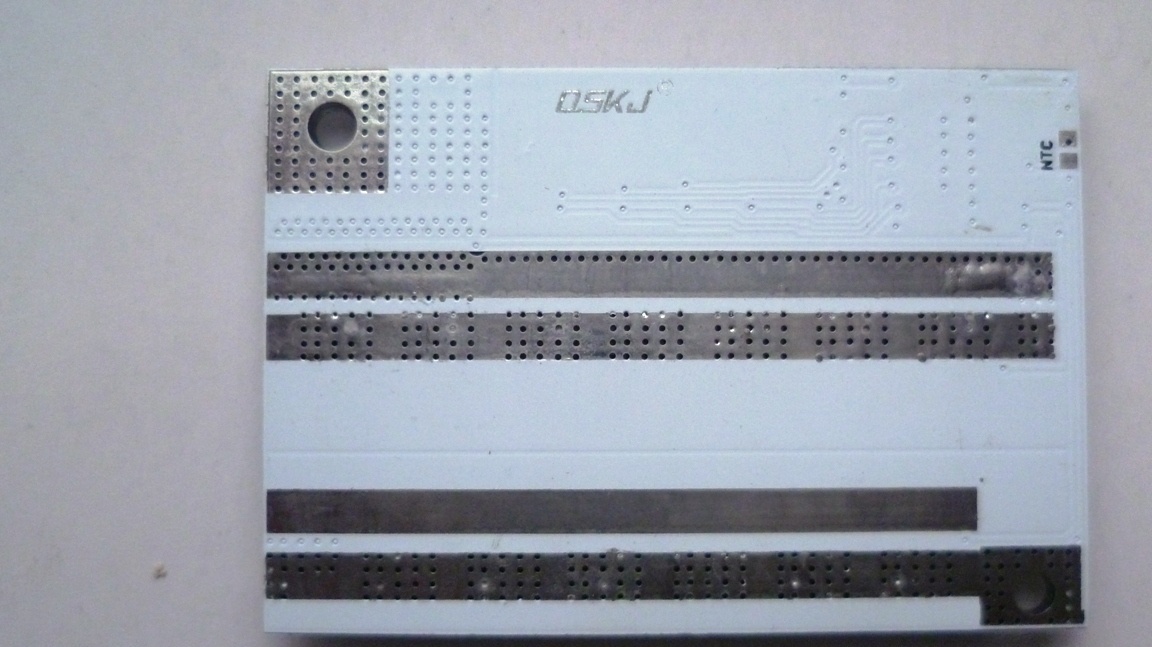
The BMS controller manages the battery - it balances, monitors the temperature of the overheating of the cans and protects against overloads. All these functions significantly increase the battery life. On the back of the BMS board there are NTC contacts for connecting a thermal relay sensor. This sensor can control the temperature of the battery case.
More details of the BMS work process and the test of the converted screwdriver can be seen in the video
I wish you all health and success in life and work!