
Why do we need dc-dc step-up voltage converter, I think everyone knows. They are different, but are built on the same circuitry.
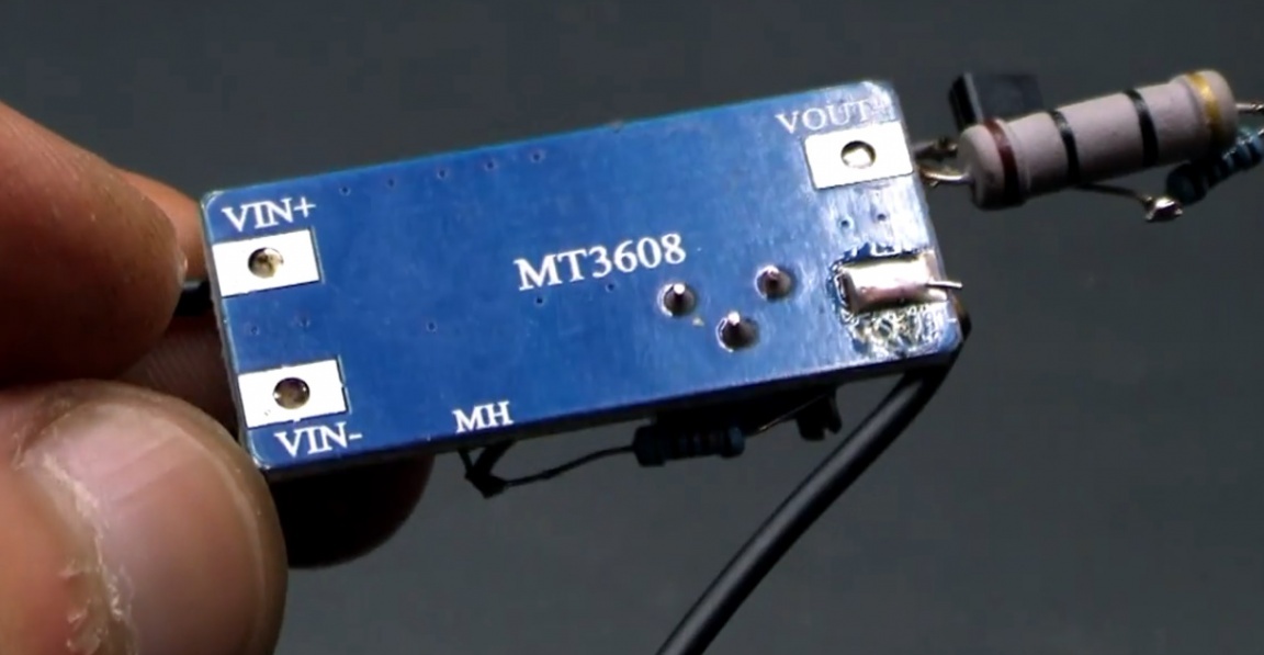
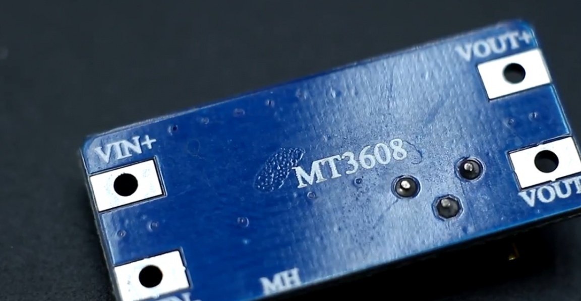
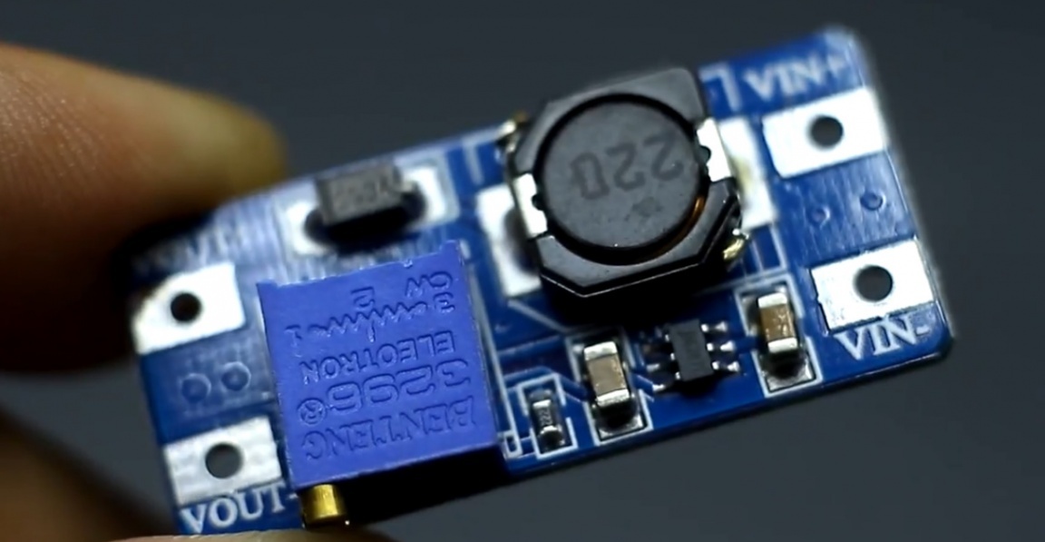
The mt3608 converter shawl is the most popular among them. It’s worth a penny, has good characteristics. In general, this board, we are amateur radio enthusiasts, we introduce anywhere.
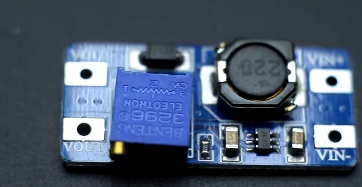
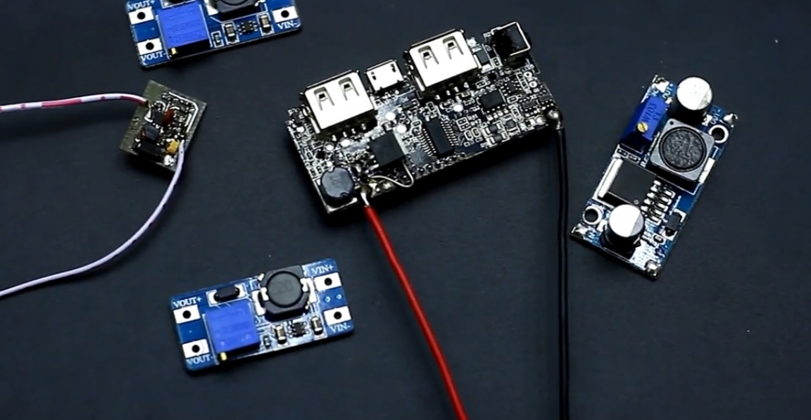
There are many modifications to this board on Aliexpress. This scarf is quite economical. The open circuit current is only 1-1.5mA, but it all depends on the power source.
This converter many modify, reducing ripple. As a rule, refinement concerns only the input and output parts, the addition of smoothing capacitors, and so on.
Today, the author of AKA KASYAN presented his version of finalizing this board, which:
1) will drastically reduce the idling current;
2) will allow this boosting dc-dc converter not to be afraid of short circuits and overload.
Very often, a converter of this type of amateur radio is used to power the multimeter from a low-voltage source. This is done to save money on batteries of type 6F22 ("Krona").

In idle mode, 1-1.5mA of current is a lot. This option will reduce the no-load current, attention, to 60 μA - and that's cool!
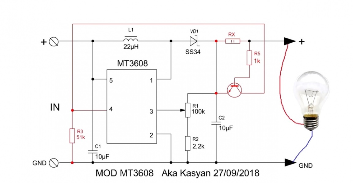
A super-economical converter that can be left on as long as you like. It consumes almost nothing. Let's first look at the original converter circuit:
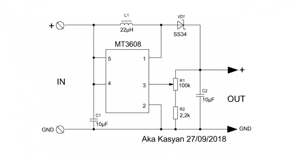
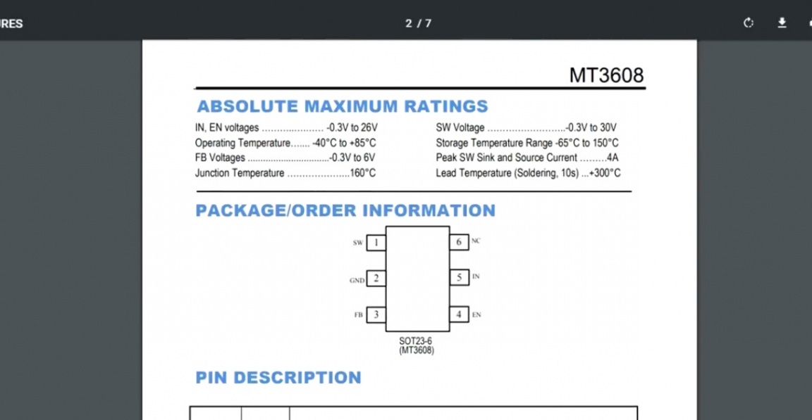
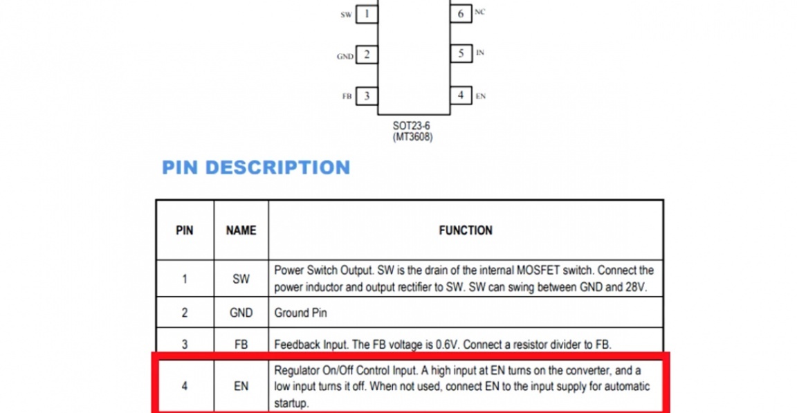
Here you need to pay attention to the 4th output of the chip. This is the drive control pin. In the original circuit, it is closed with a plus power.
If it is shorted to ground, the converter will be cut off and the output will have the voltage that is at the input minus the voltage drop at the junction of the diode.
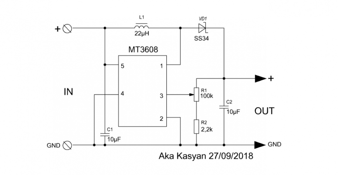
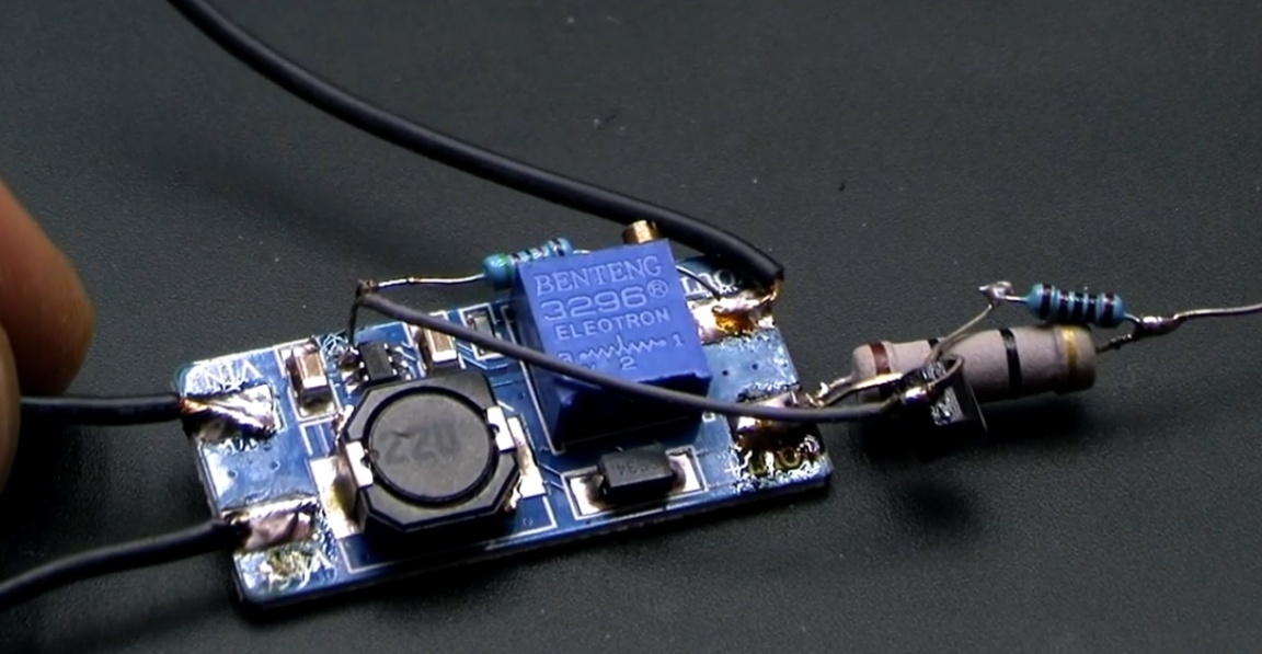
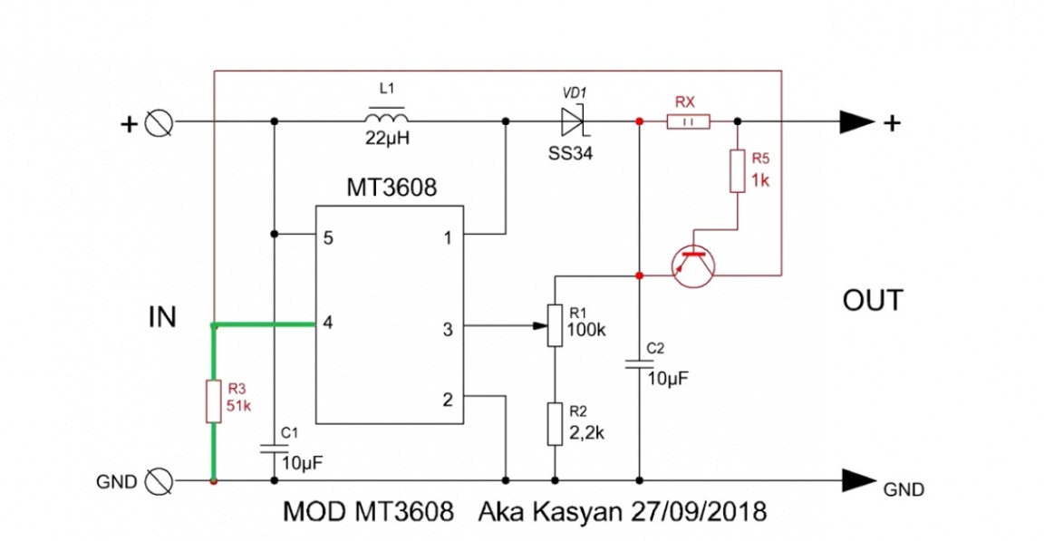
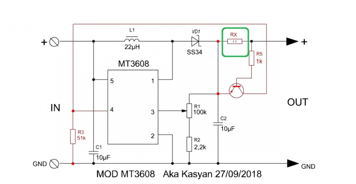
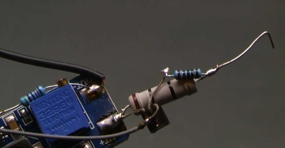
And here is the author’s alteration option:
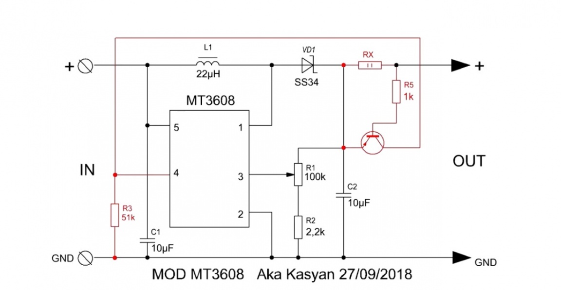
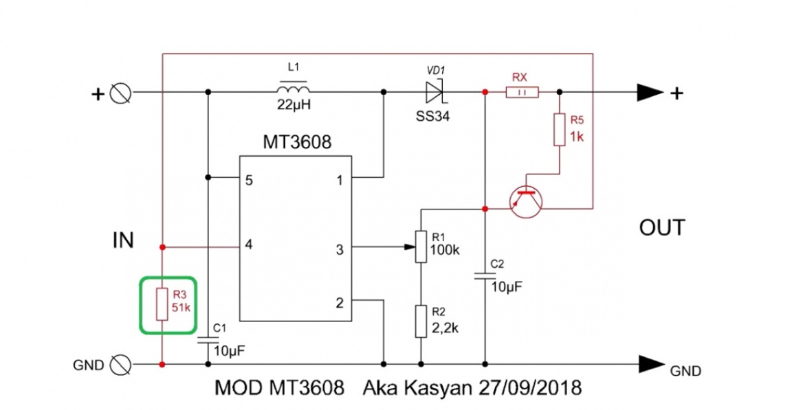
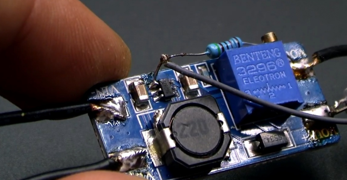
The fourth pin is disconnected from the plus and through the 50k ohm resistor is pulled to the power supply.
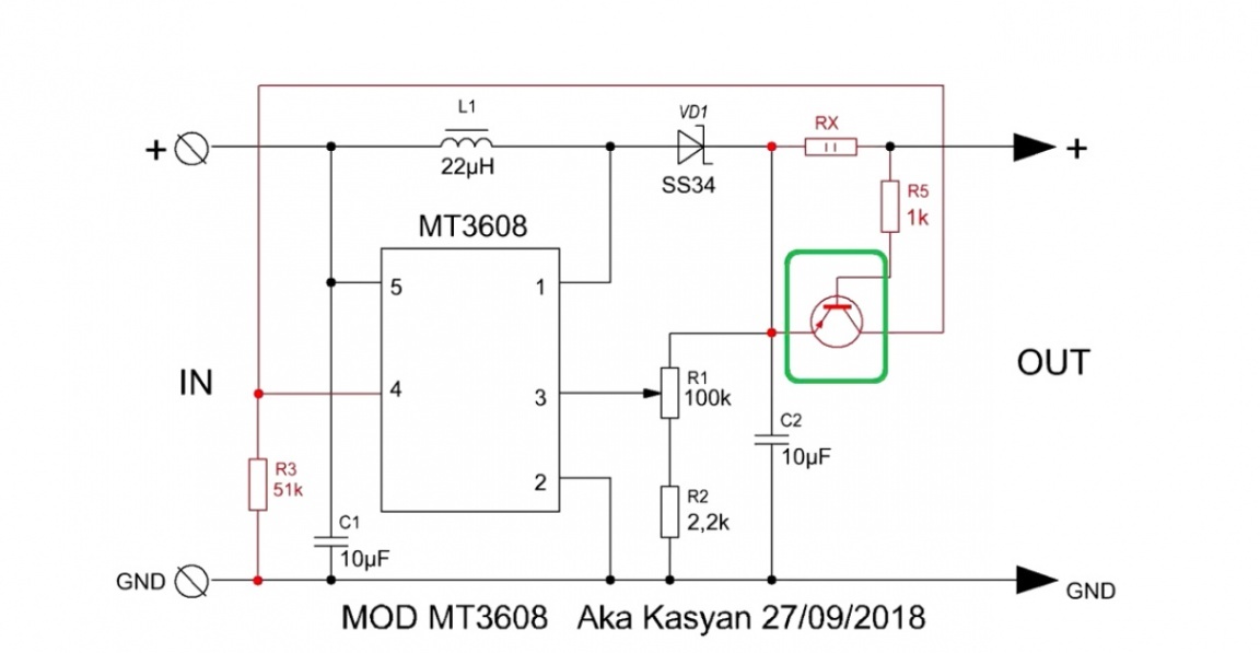
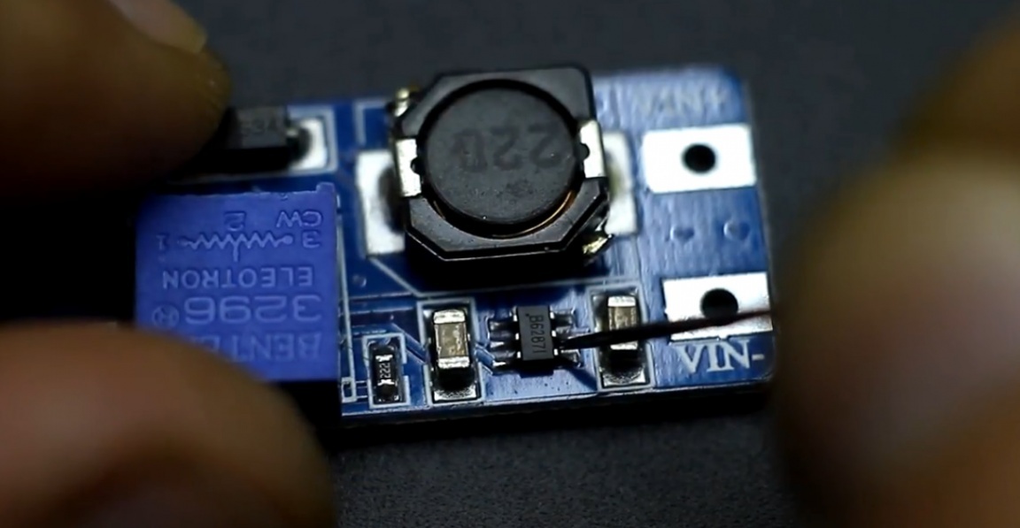
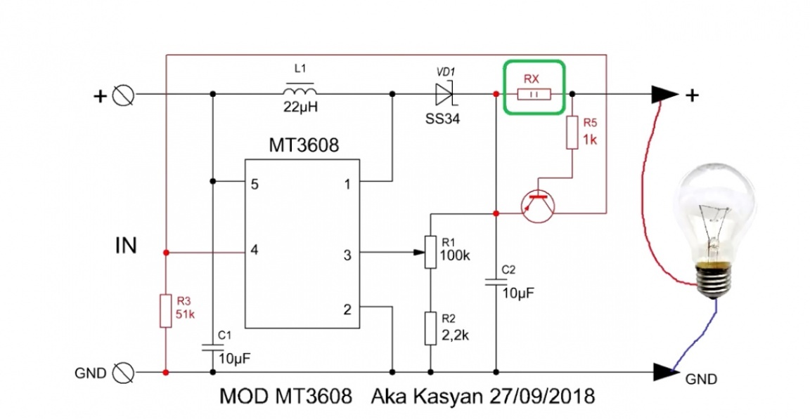
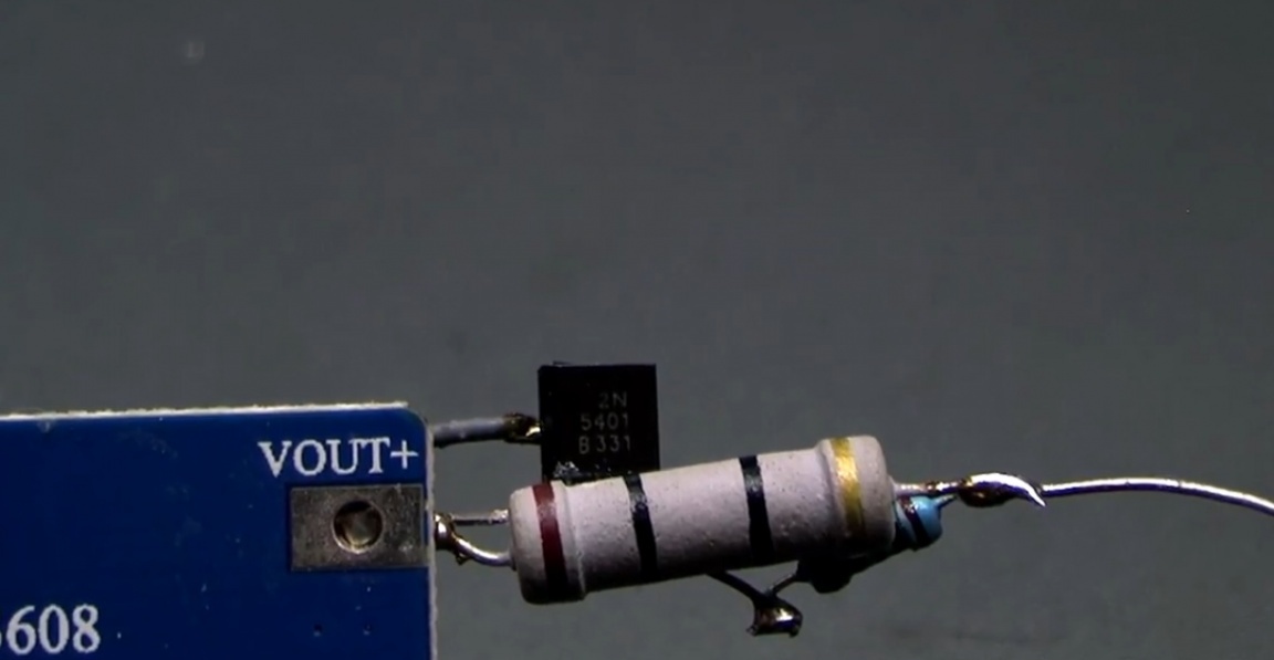
A current sensor in the face of the RX resistor and a low-power direct-conductivity transistor, the collector of which is connected with the 4th output of the microcircuit, is connected to the converter output.
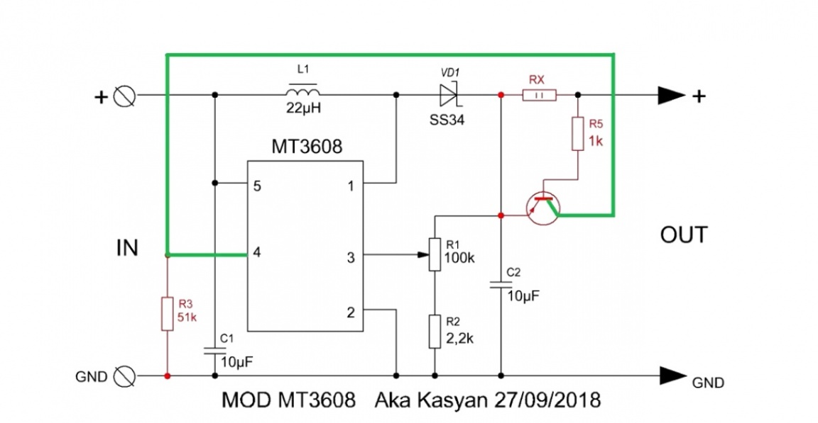
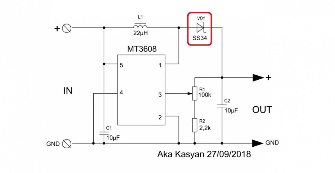
On this board, the 4th pin of the microcircuit is closed with the 5th.
You can disconnect them with a clerical knife blade or a needle.
Now about how it works. If pin “4” is shorted to ground, the converter is essentially turned off and consumes a meager current of 60 µA from the power source.
But there is a voltage at its output, which is equal to the supply voltage. If a load is connected to the converter output, a voltage drop is formed at the current sensor.
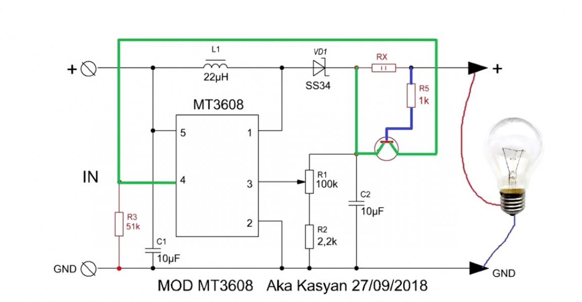
This drop is enough to trigger a low-power transistor. On the open junction of the transistor, plus (+) power is supplied to pin “4”. As a result, the converter starts up and at its output we get an increased voltage.
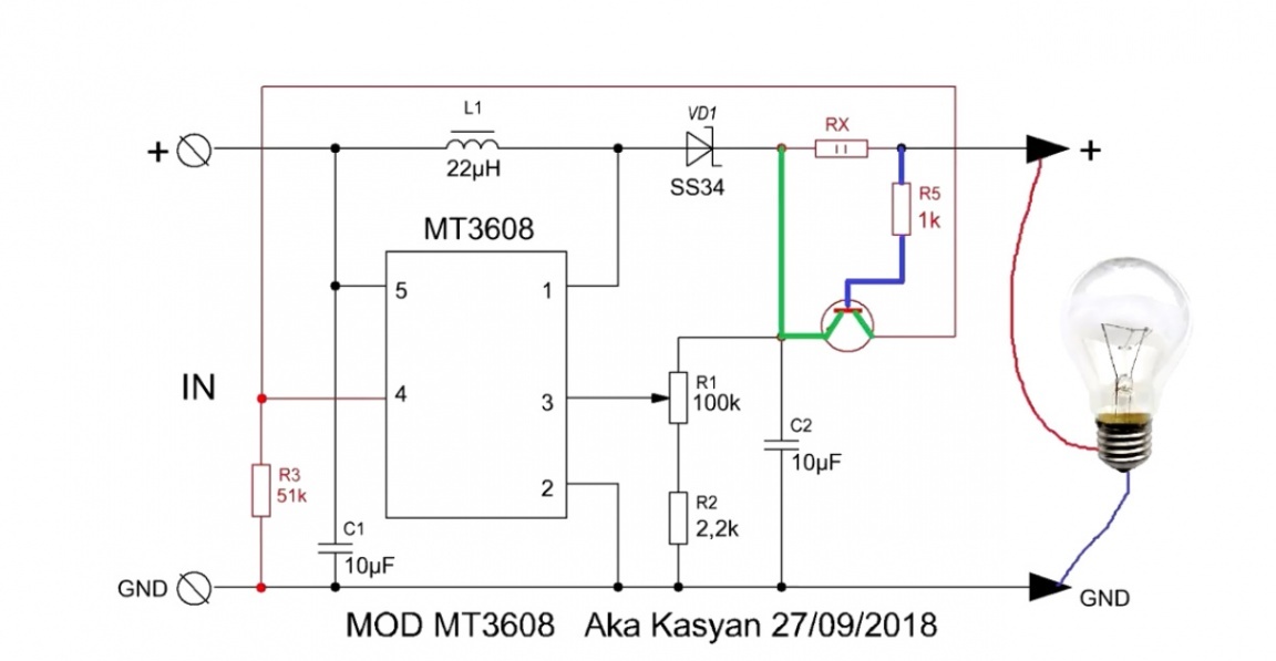
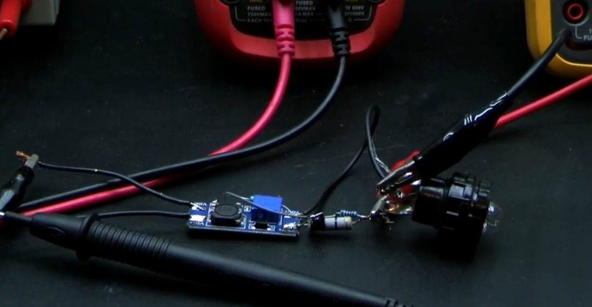
In other words, if there is no load at the output, the converter is turned off, if the load is connected, the converter starts automatically. But more clearly:
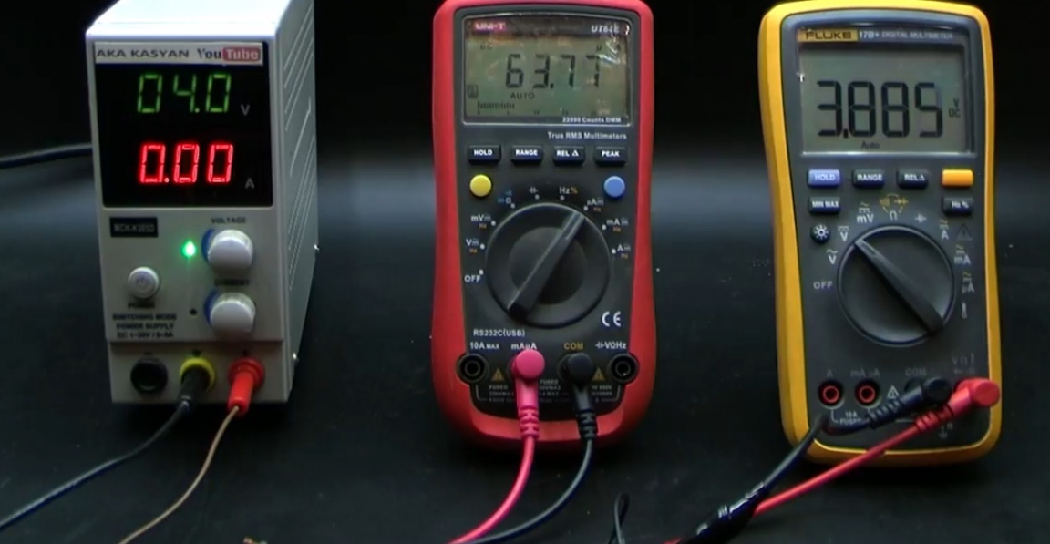
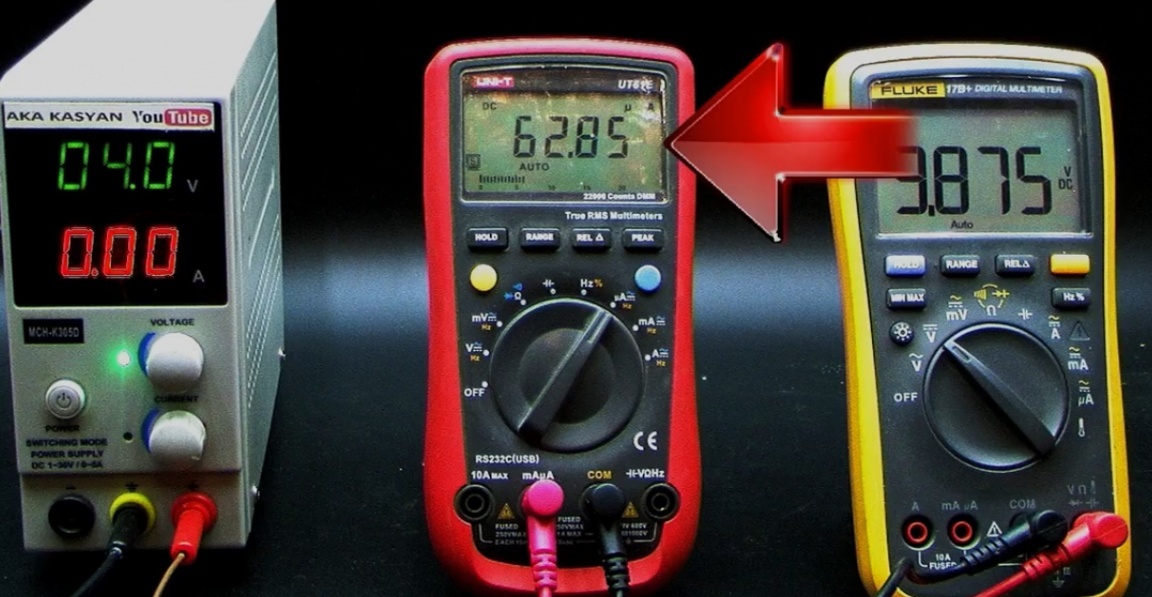
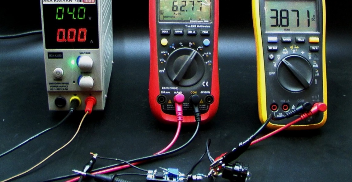
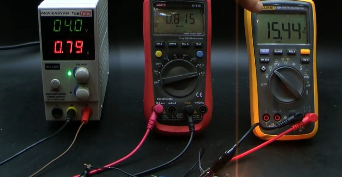
About 4 volts are supplied from the laboratory unit to the input of the converter. The red multimeter shows the current consumption of the converter. The second multimeter shows the voltage at the output of the converter, and as you can see, the output voltage is equal to the input, and the current is only 60 with a penny of microamps. The drive is disabled in this state. One has only to connect the load (in this case, a small incandescent lamp) and the converter instantly starts.
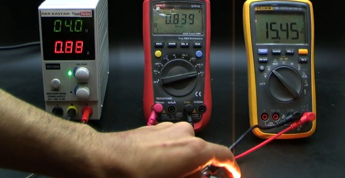
The voltage at its output increases to a predetermined value. Now about the load current at which the converter will trip. If the load consumes a very small current, for example, a multimeter, then it is worth increasing the resistance of the resistor, otherwise the drop on the current sensor may not be sufficient for the transistor to operate and the converter to start up later. The resistor also limits the maximum output current. The limiting current directly depends on the resistance of the resistor and the voltage converter installed at the output.
In the above circuit, you can add a voltage divider.
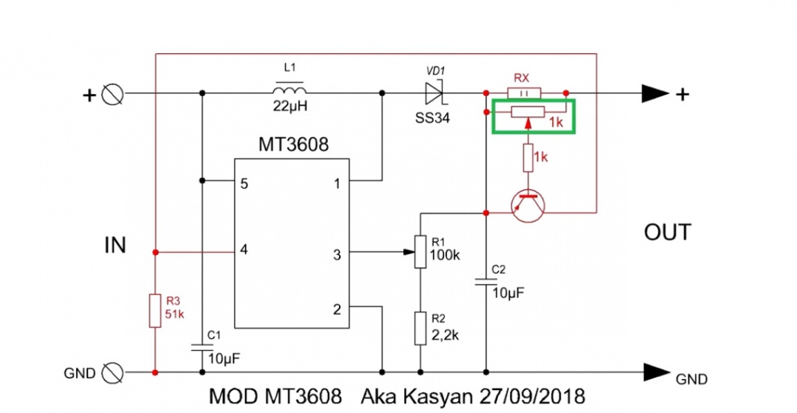
This will make it possible to regulate the operation of the transistor, since with this divider you can change the bias voltage. A transistor is desirable with a large gain, for example, composite. This will make it possible to reduce the resistance of the resistor, and, consequently, the loss on it. The power of the resistor also needs to be selected depending on the current of the output load. The only drawback of this circuit is the resistor. On it, as already mentioned, there will be losses depending on the power of the connected load and the resistance of the resistor. The lower the resistance, the less it will heat up. But if you reduce the resistance very much, then the transistor may not work.
AKA KASYAN only shared the idea and explained the principle of work. The resistance of the resistor must be selected based on your needs.
Thank you for attention. See you soon!
Video: