
Greetings the inhabitants of our site!
I think you have often met such a thing as a winding switch for a linear power supply.

But what if everything can be done much more technologically? Are you intrigued? Be sure to read to the end.
The author of this homemade product is Roman (author of the YouTube channel "Open Frime TV"). In his past videos, he collected linear and switching power supplies. And so he came up with the following: what if we combine these 2 power supplies into one and get a perfect device with a very high efficiency?
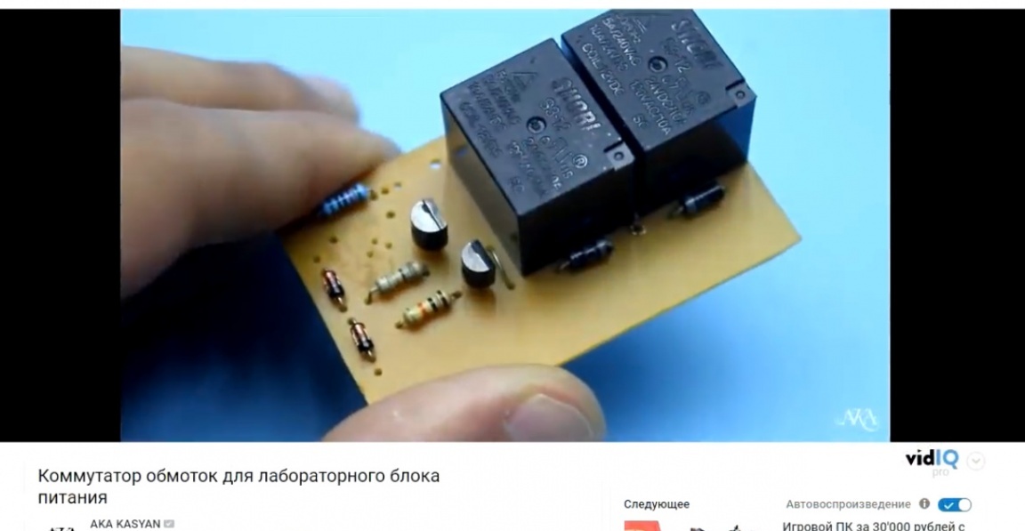
The meaning of such a circuit is similar to a winding switch. This was somehow done by AKA KASYAN, the author of the channel of the same name on everyone's favorite video hosting YouTube.
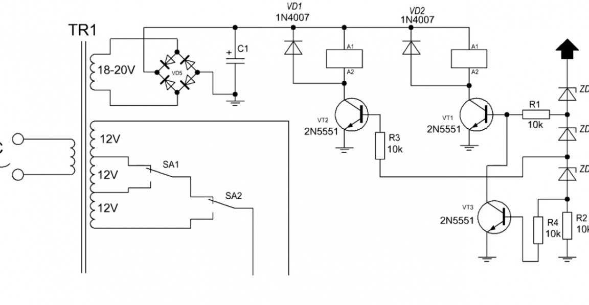
It consists in the fact that different voltage from the steps of the transformer is supplied to the input of the linear power supply unit. If we need a voltage of 8V at the output, then we work at the first stage, at which 12V is allowed to be input.
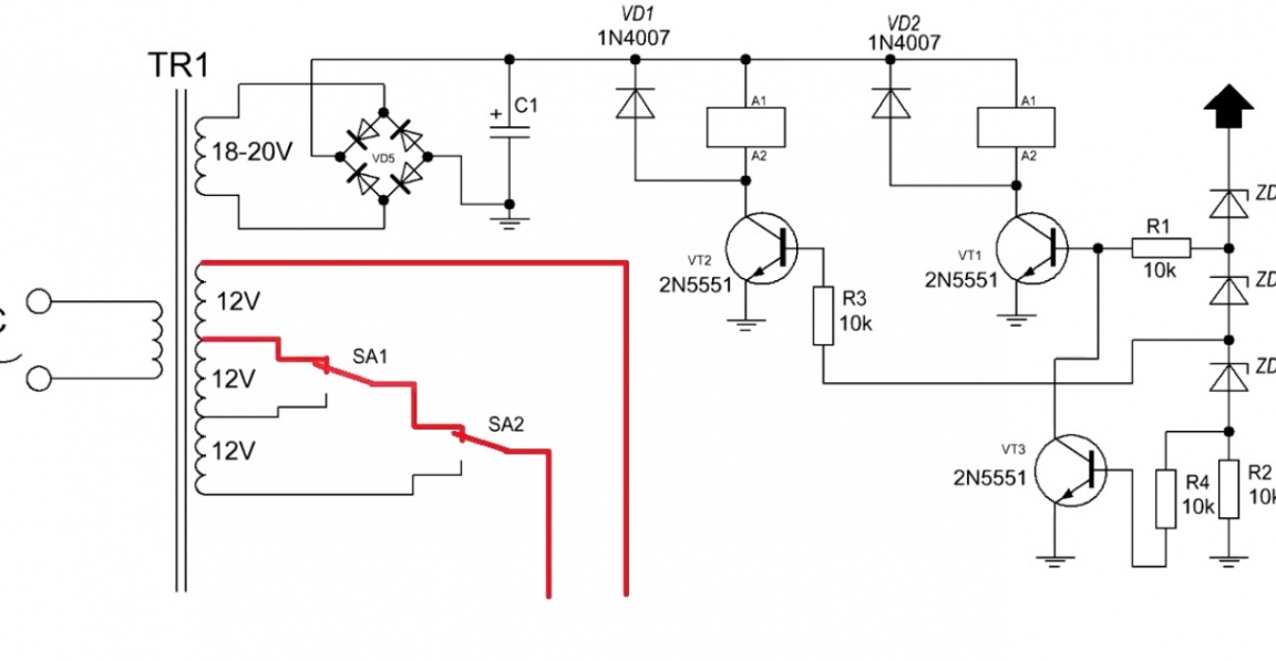
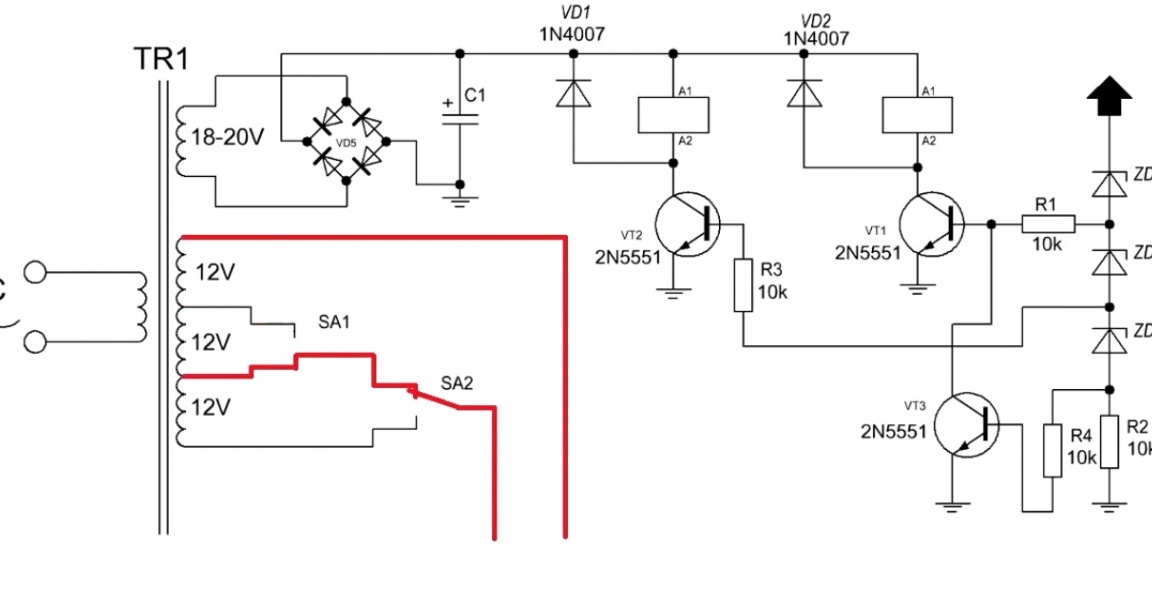
If we suddenly needed to get a voltage of 15V at the output, the device switches us to the second stage, which supplies a voltage of 24V to the input.
All this is cool, the efficiency in comparison with an ordinary liner has increased, but still you have to dissipate quite a lot of heat. Plus, you need a transformer with bends.
And here the question arises: What if we combine a linear power supply and a switching power supply? The block diagram looks like this:
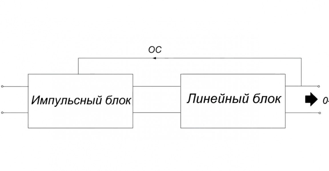
We hang linear on the output of the pulse block and make feedback from the output of the linear indicator.
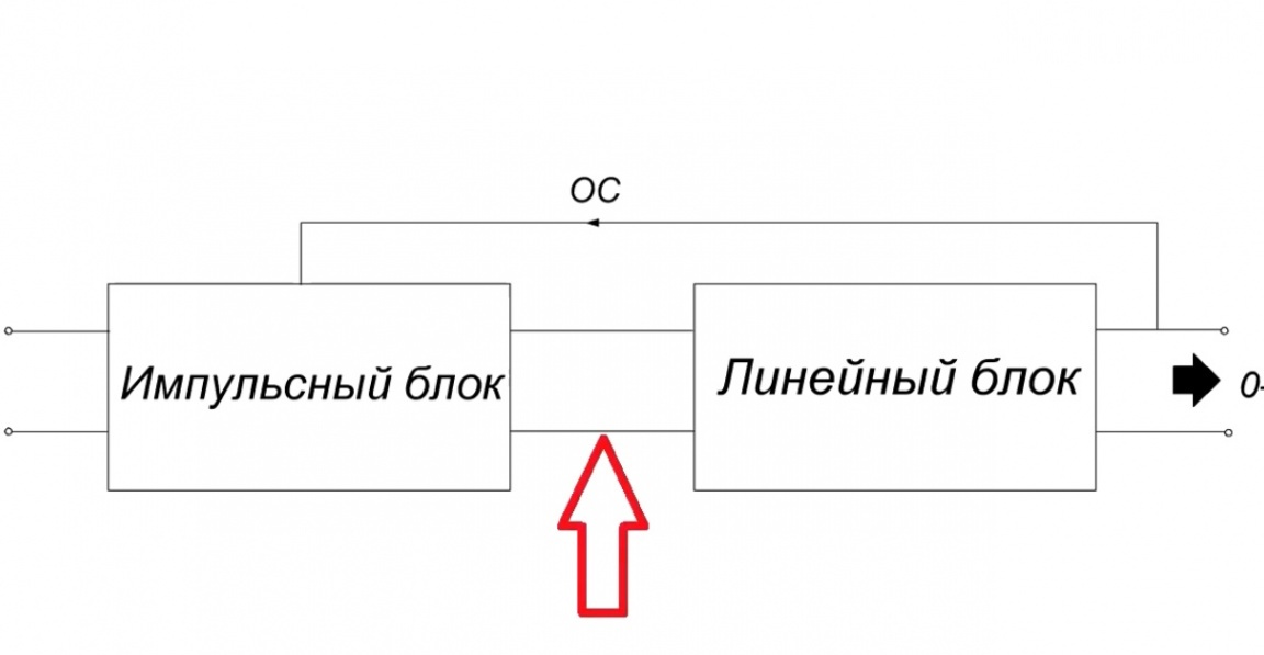
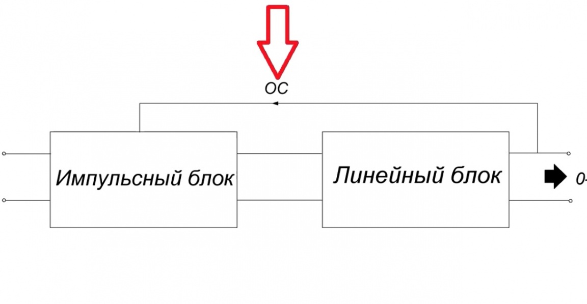
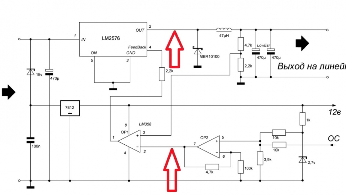
The main task is to ensure that the voltage at the output of the switching power supply is always a couple of volts higher than at the output of the linear power supply.
And now I propose to consider how the author realized this.
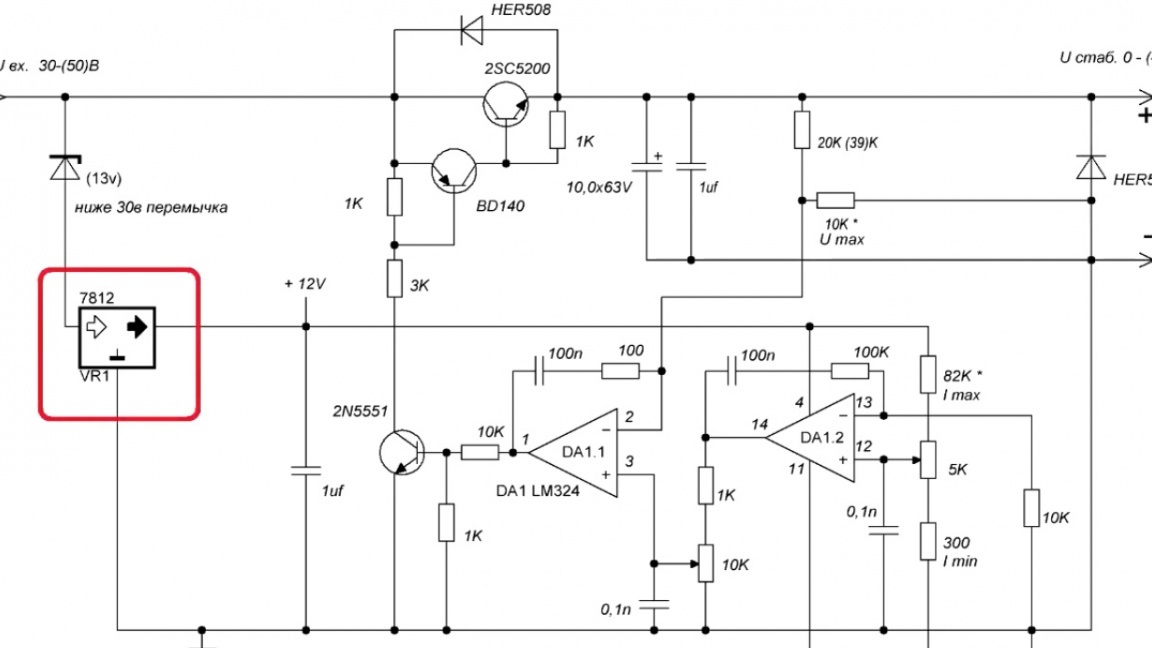
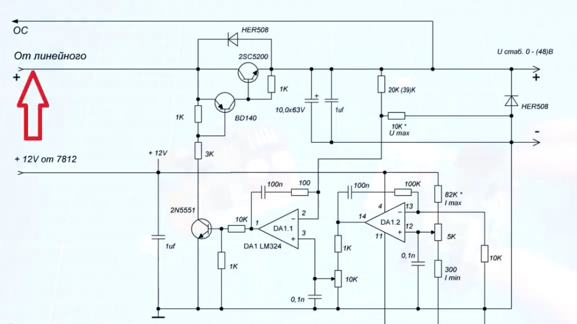
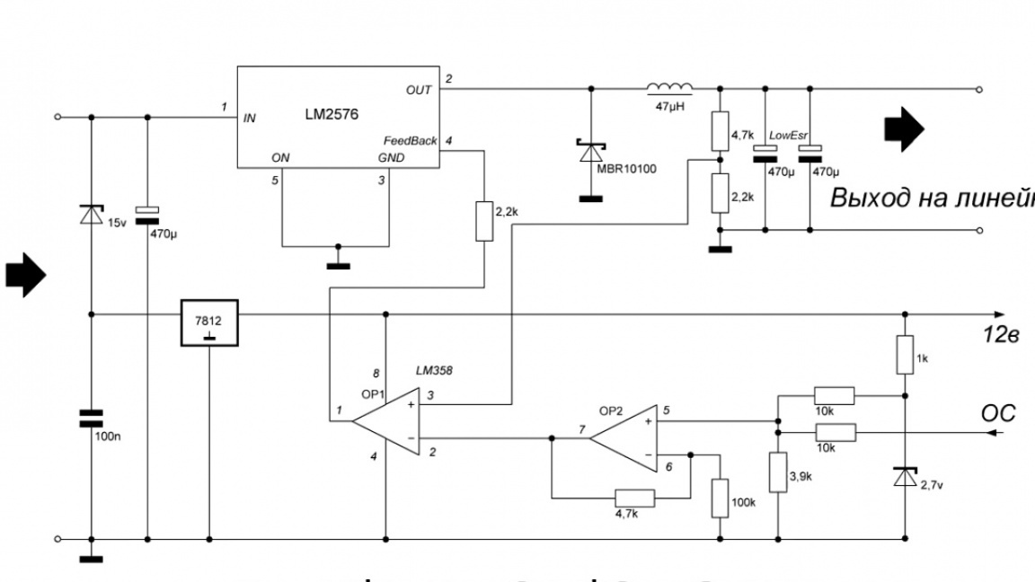
The circuit and board of the linear power supply remained virtually unchanged. Feedback will be taken from the output of the block and, as we see, the author removed 7812, due to the fact that less than 12V voltage can come to the output of this circuit.
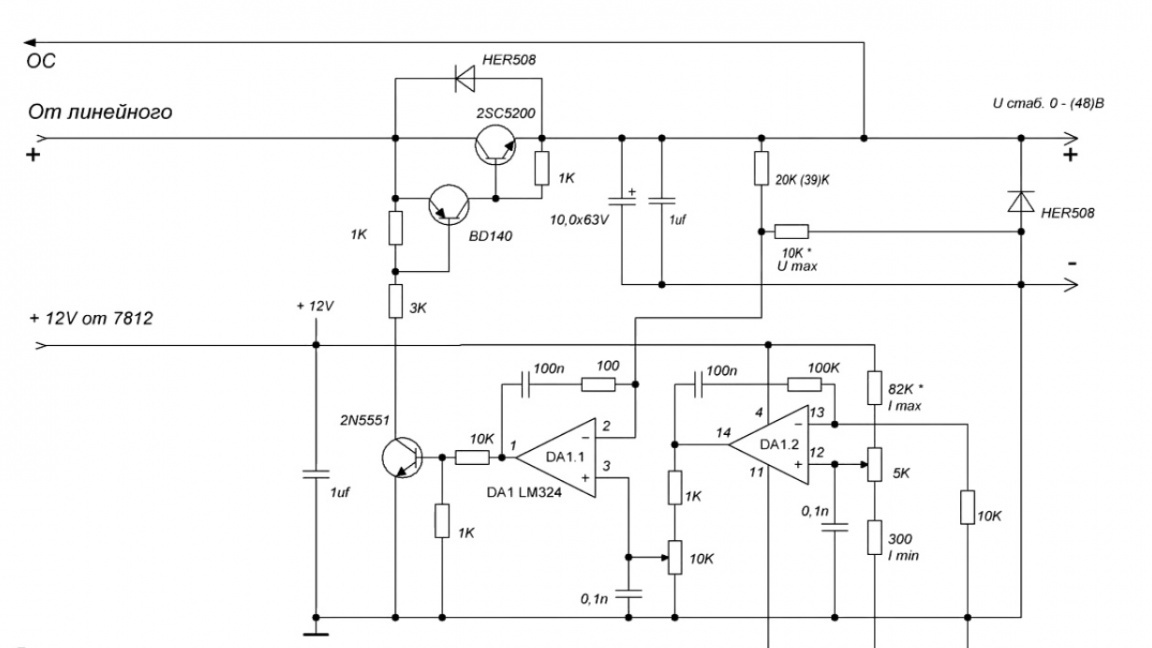
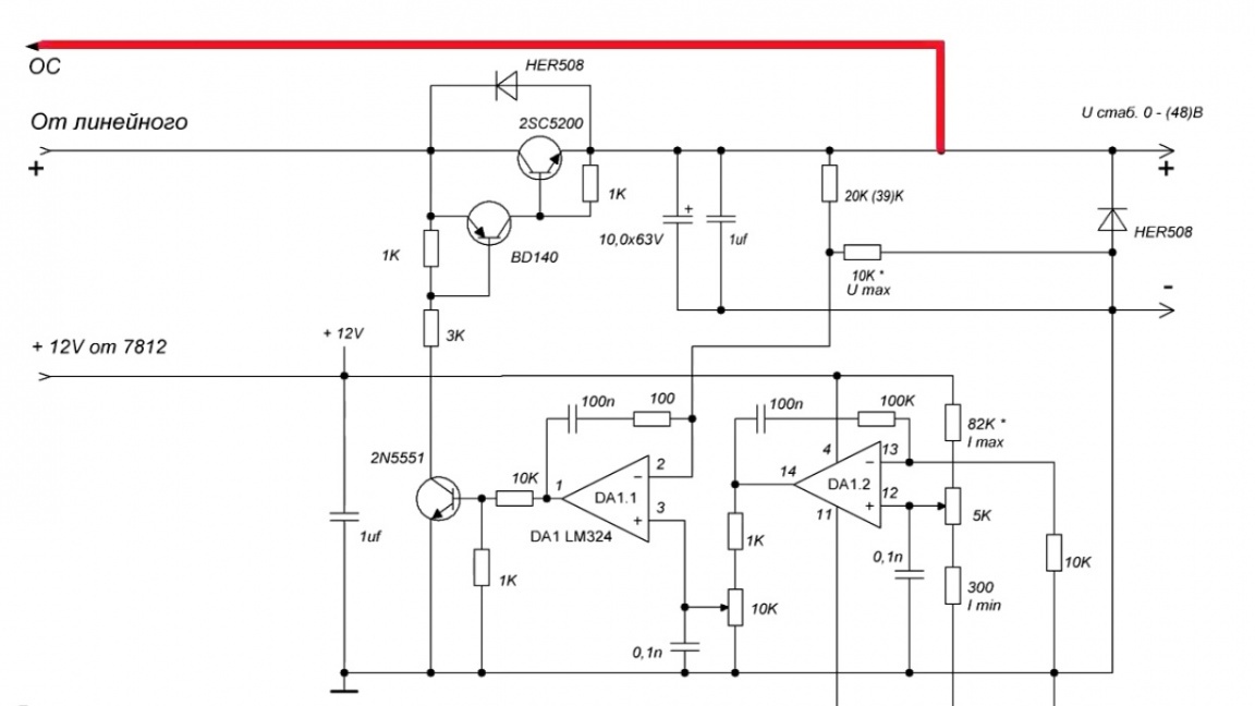
Therefore, we remove 7812 and solder the wire here. It will be connected to the pulse board on which the same 7812 is installed.
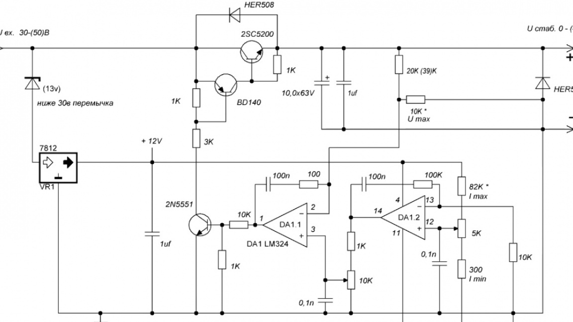
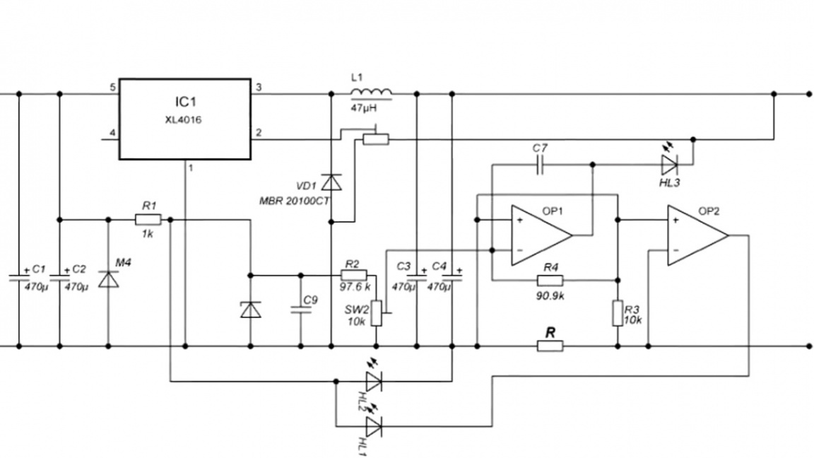
That's all the changes for the linear power supply, now we look at the pulse generator circuit.

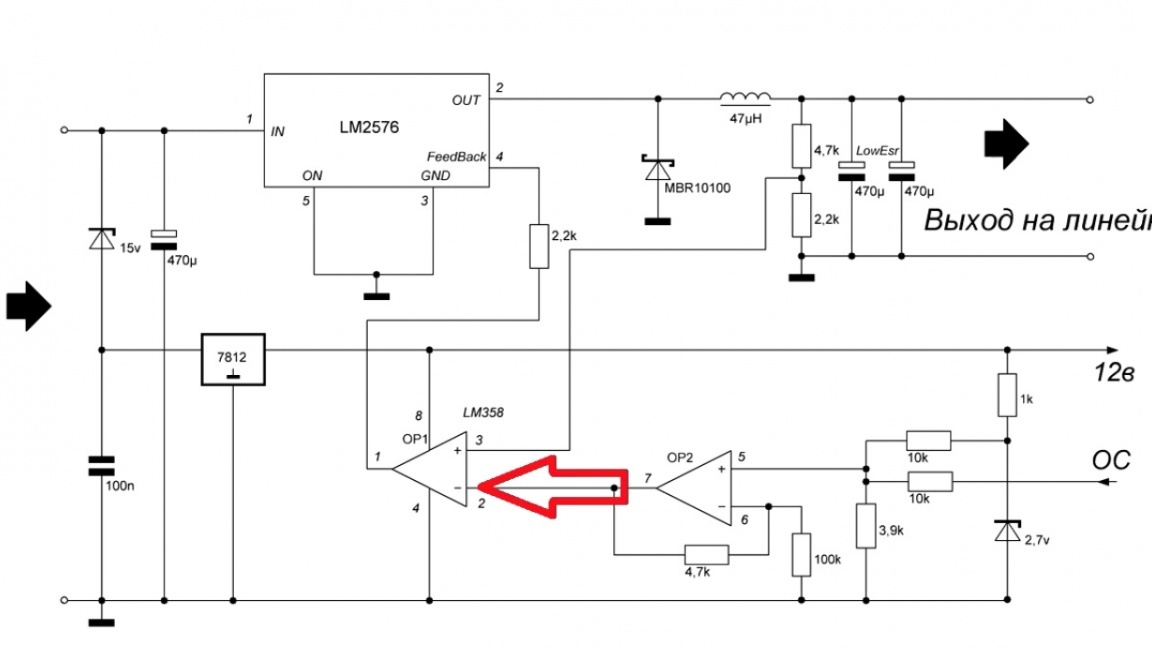
There will already be more changes. First, let's see how the idea of a tracking system is implemented.
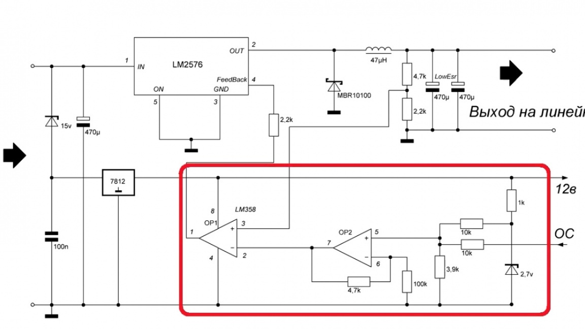
And it is naturally implemented on an operational amplifier.
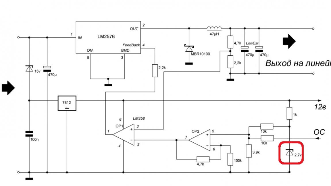
It is included in the circuit from the adder, here there is an addition of 2 voltages: one reference, specified by the zener diode; another from the output of the linear power supply.
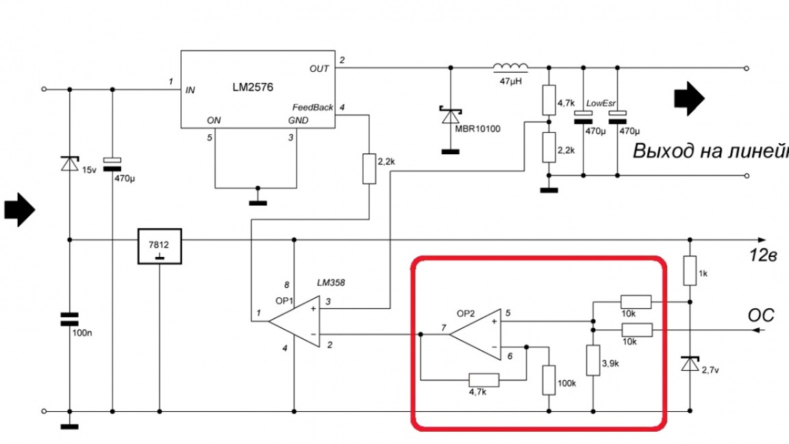
By changing the value of the zener diode, you can change the voltage increment.
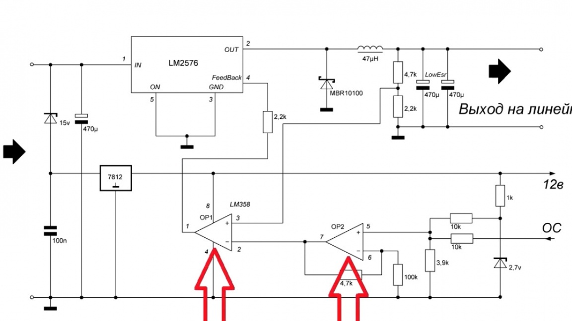
From the output of the adder, the voltage goes to the 2nd operational amplifier, which, as in the usual pulse generator circuit, tries to equalize the voltage at its inputs, one voltage that we set, and the second directly from the output of the microcircuit.
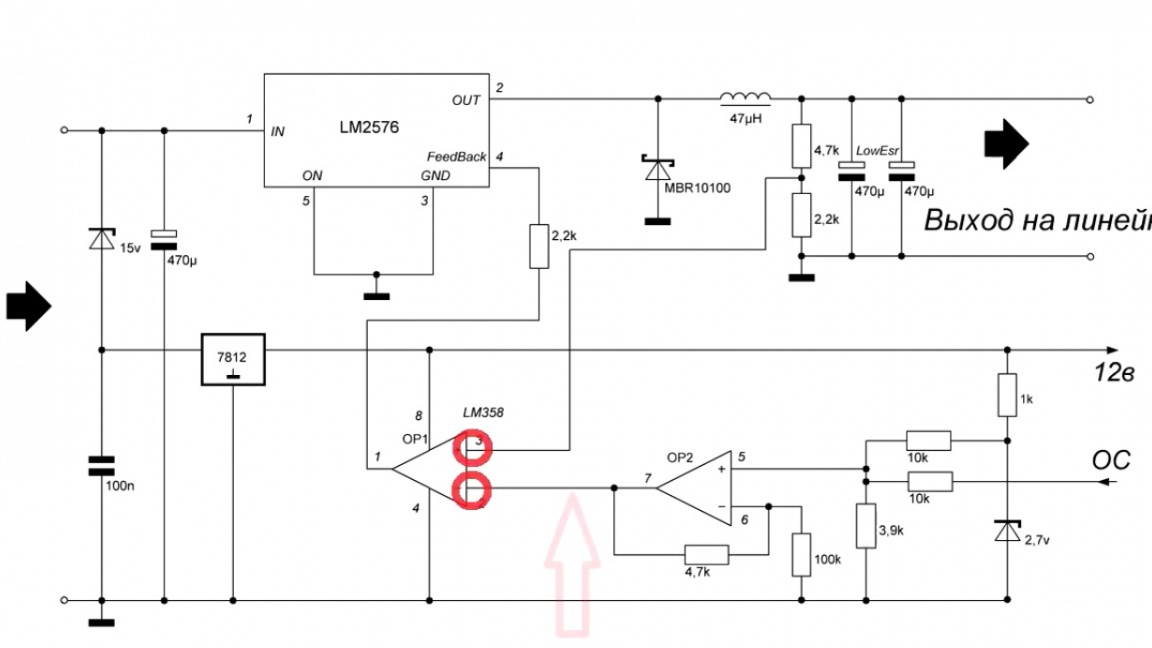
As you can see, the meaning of the work is very simple and at any voltage set on the linear block, the dissipation power will not exceed 10W. According to the author, this is a gorgeous result.
You can install the lm2596 chip in this circuit without any changes.

If you need more current, then according to this topology, you can make a circuit on xl4016.
And now we move on to the next stage - the creation of a printed circuit board and implementation in hardware.
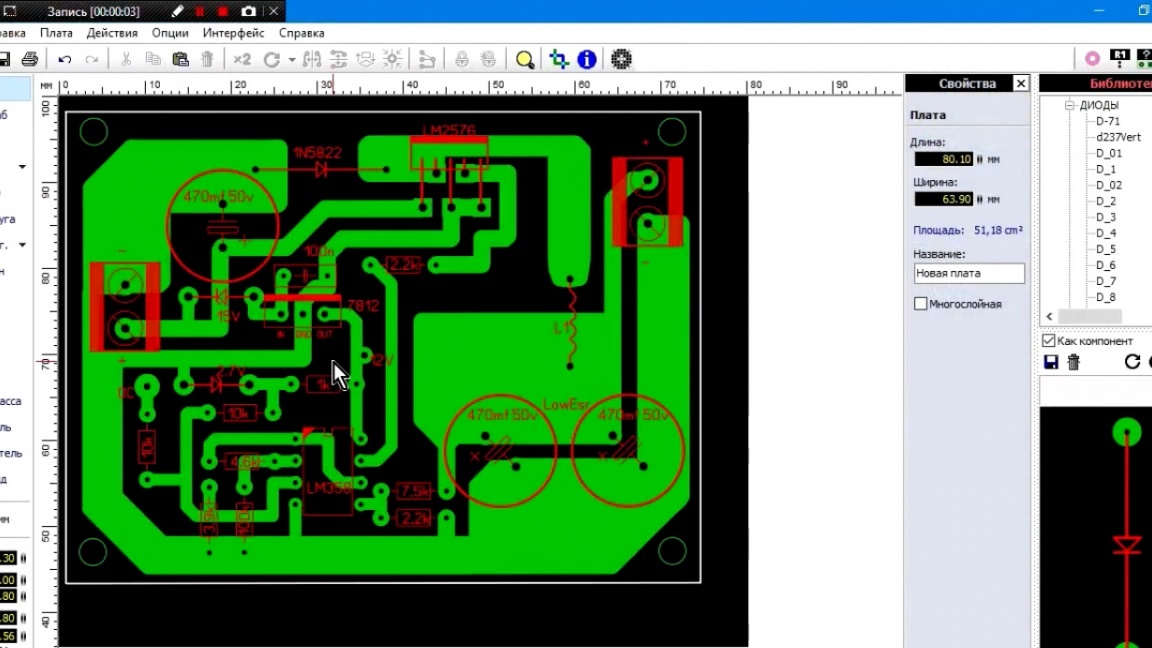
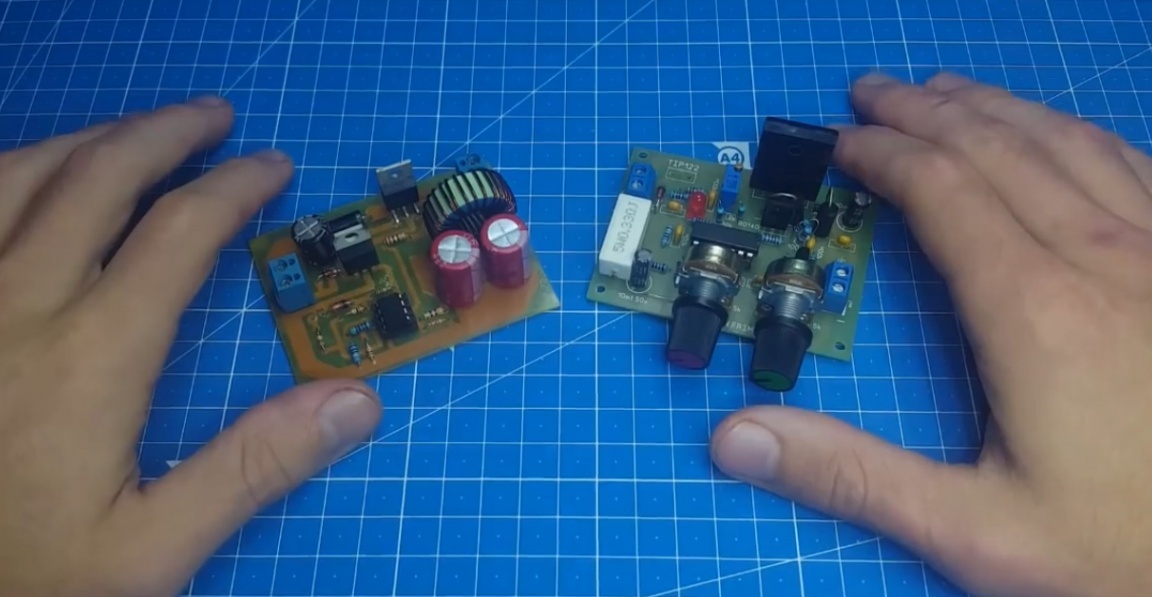
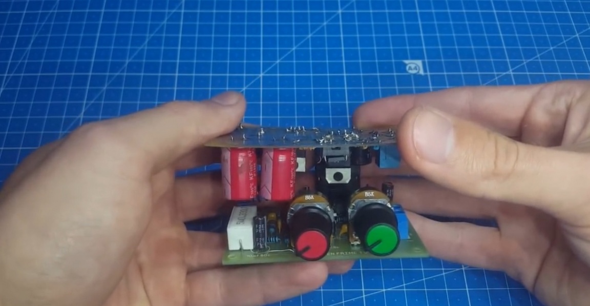
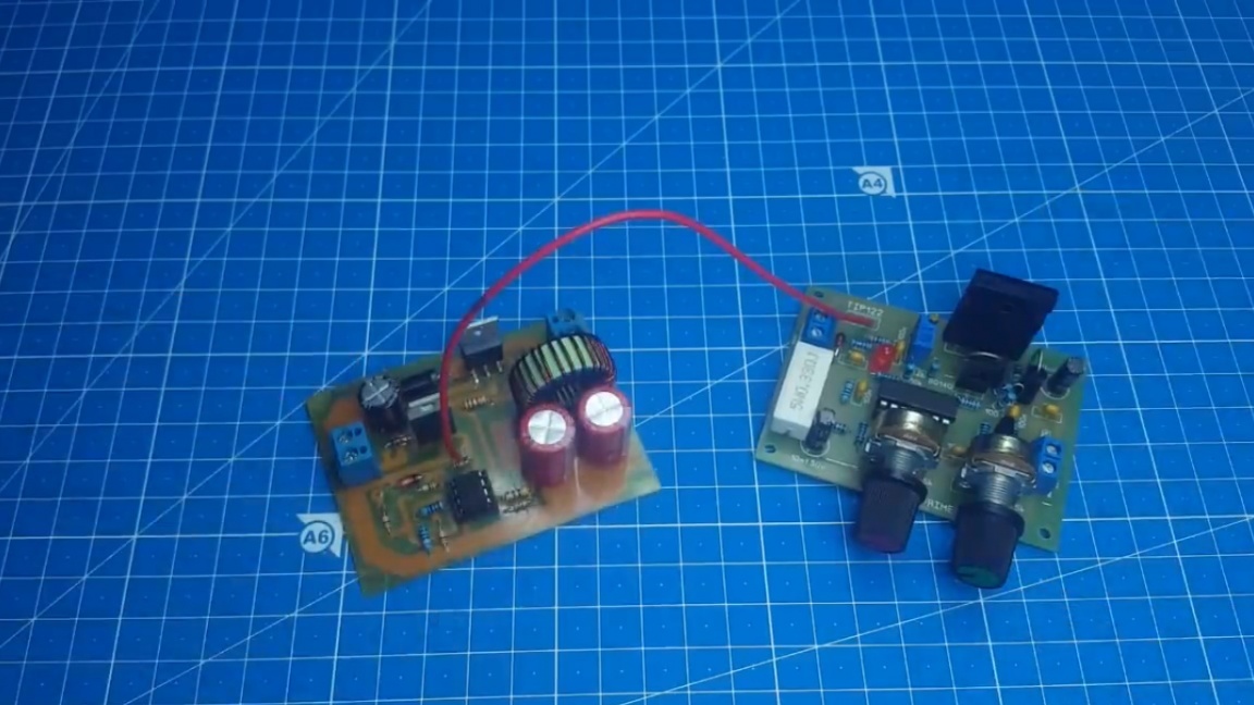
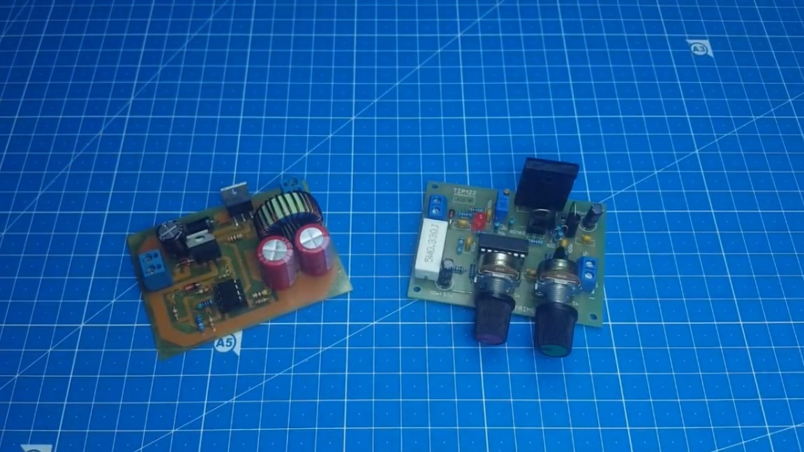
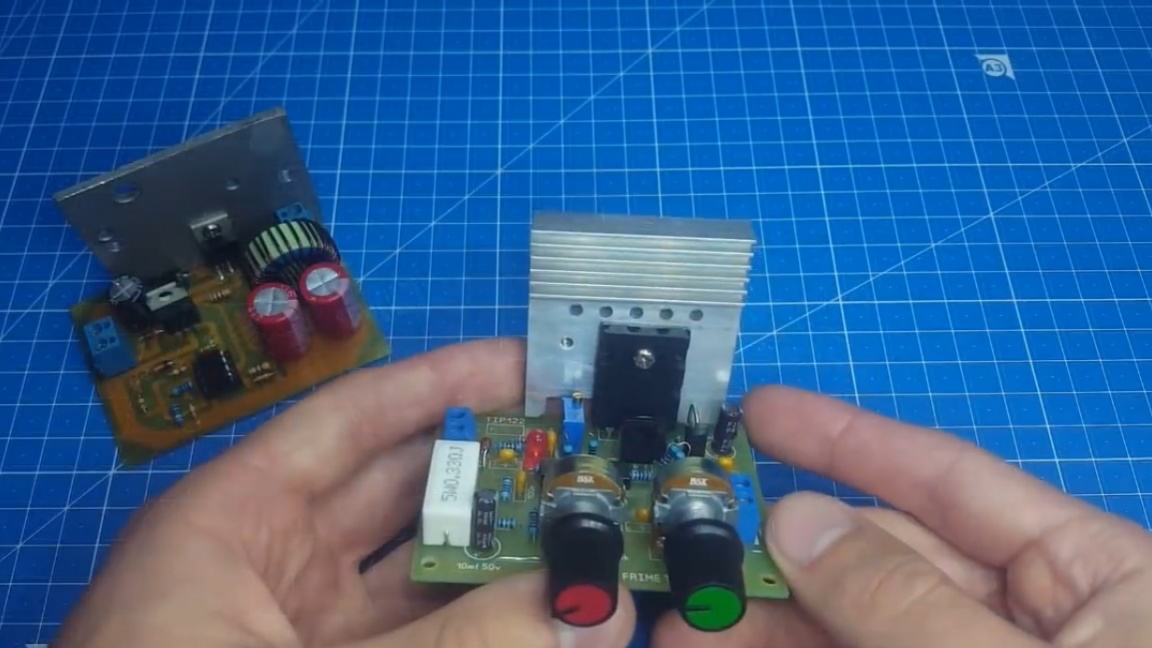
You can say that it’s stupid to enlarge the device like this, to make 2 boards that take up extra space. The author also thought so and decided to make everything very compact. He did not remodel the linear block board; it remains unchanged. But the impulse board will be made exactly the same in size as the board of the linear power supply only inverted.
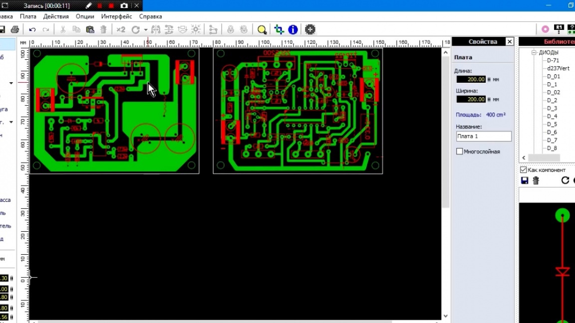
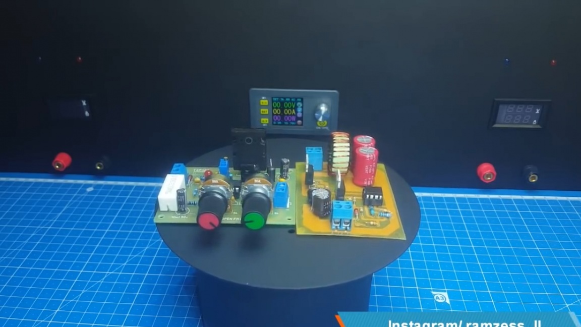
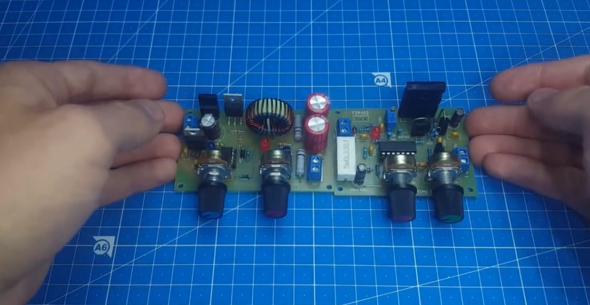
And now from 2 boards you can assemble here such a sandwich, which will be installed on one radiator, without taking up a lot of space.

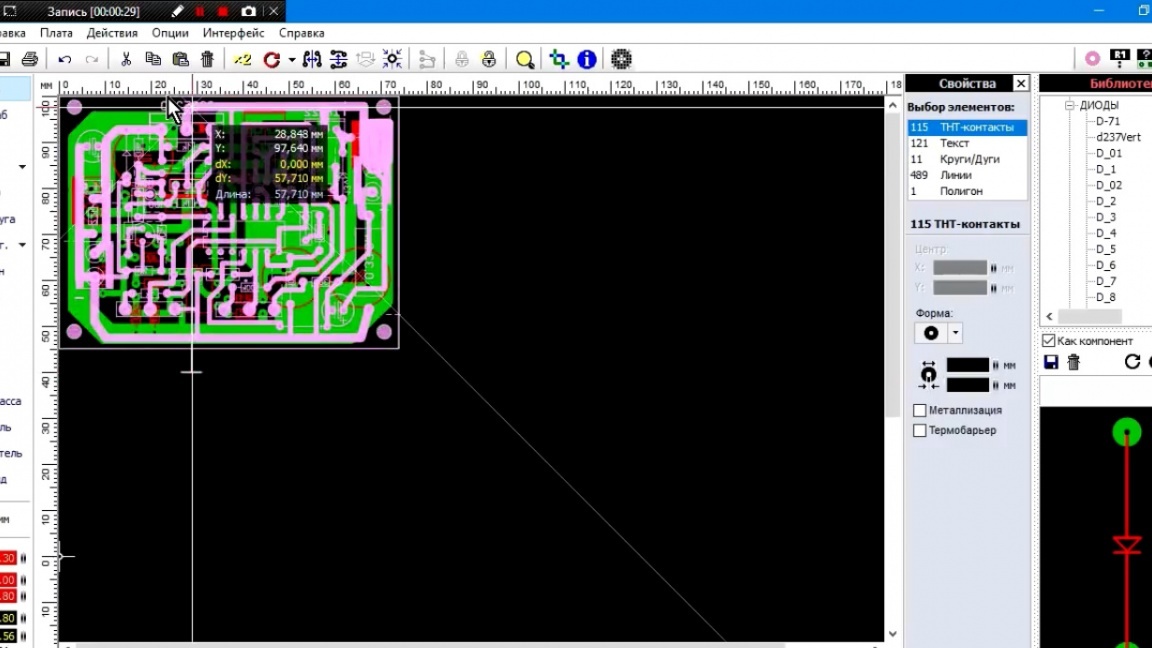
The power elements are arranged in such a way that they will not interfere with each other with such an installation. Now you can start making the printed circuit board. I think you all know how this process happens.

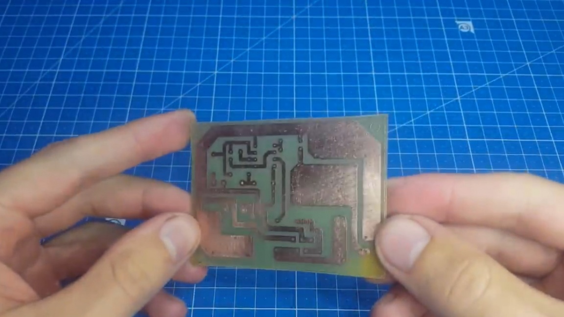
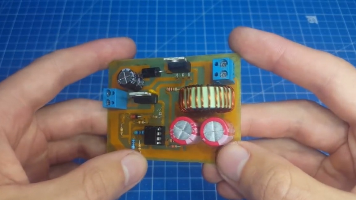
As you can see, the board is etched. Now we solder it and proceed to the tests. There are few elements here. We solder everything.
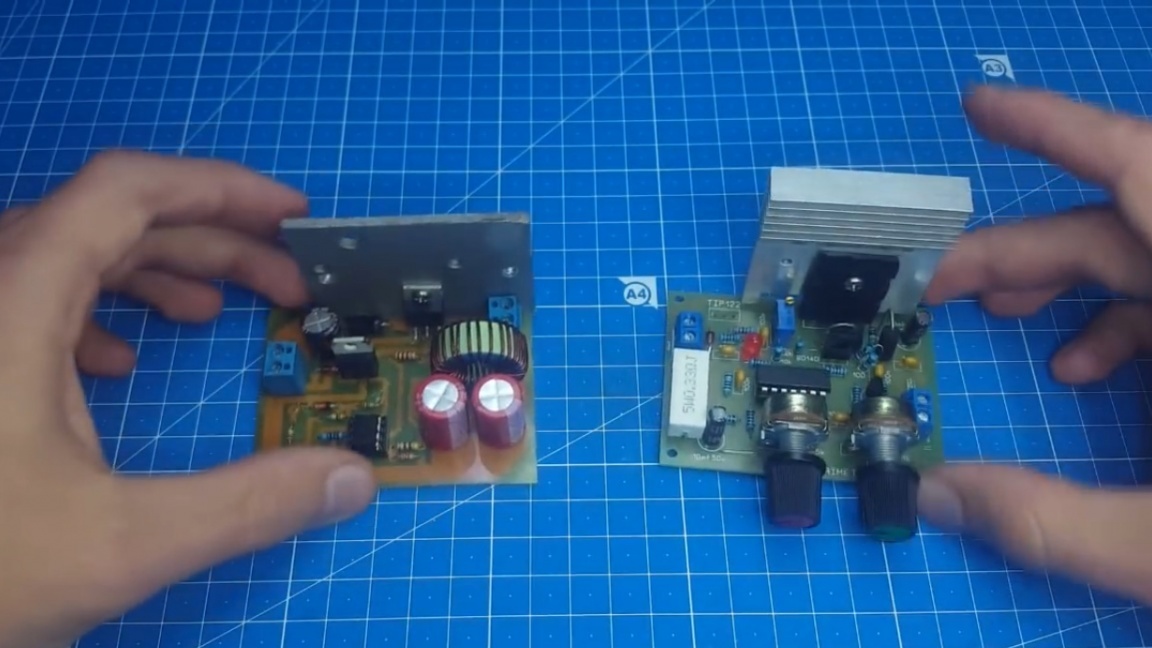
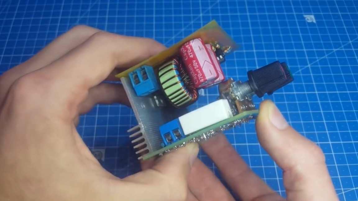
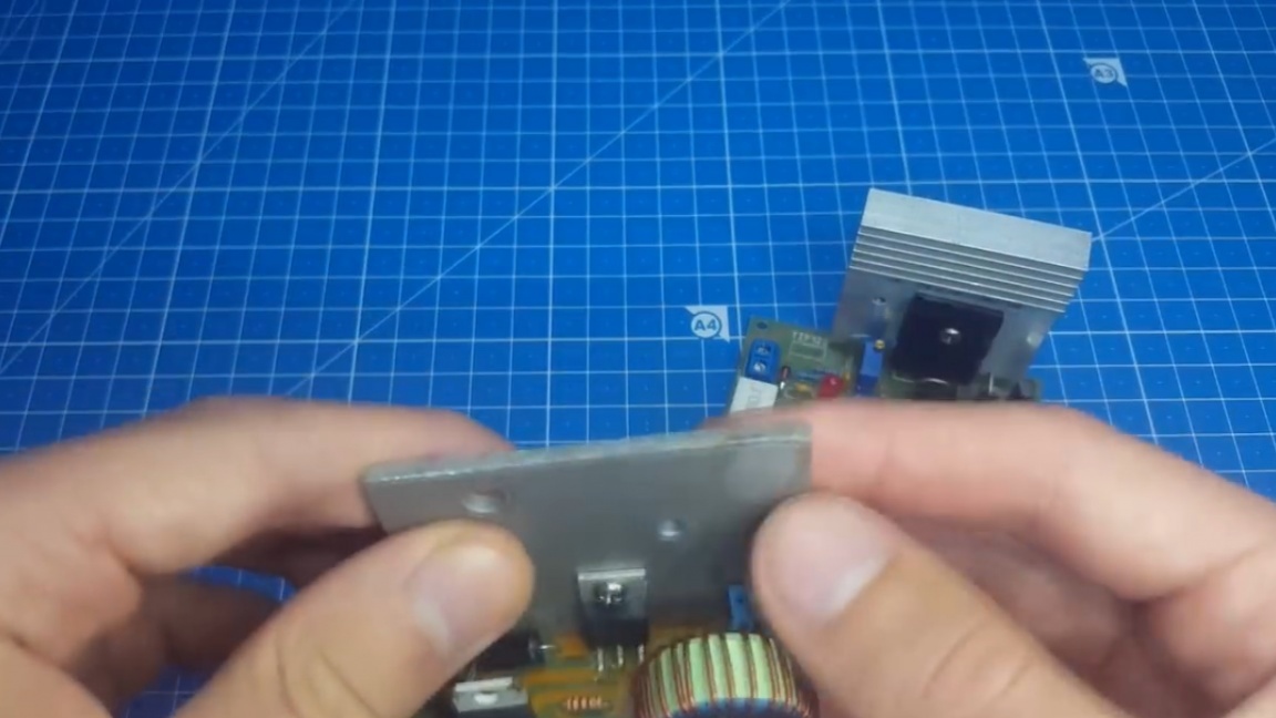
Then the author immediately wanted to pick up the boards on the radiator, but thought it was better to demonstrate the work in the disassembled state - so it will be more clearly visible. As a test radiator, he picked up a miniature radiator on the linear block:
And just a plate on a pulse generator, which is hard to call even a radiator.
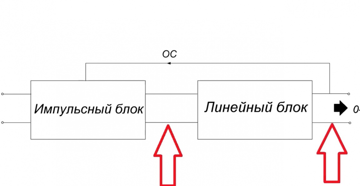
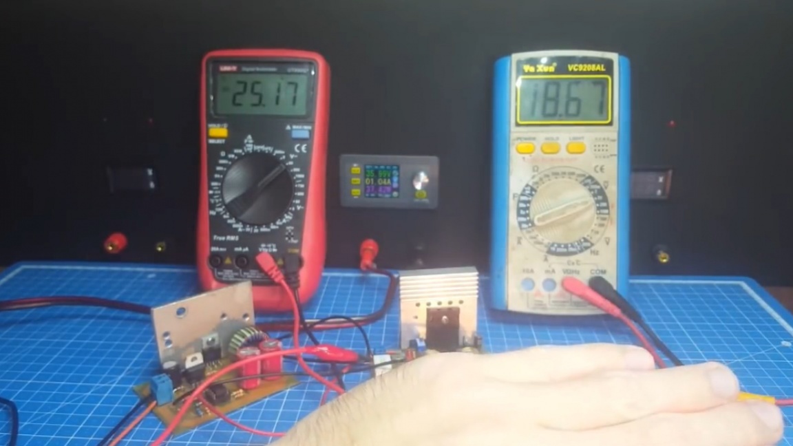
Thus, the author wants to show minimal heating of the circuit. And for the test itself we need 2 multimeters. One of them is connected to the output of the impulse, and the second to the output of the linear.
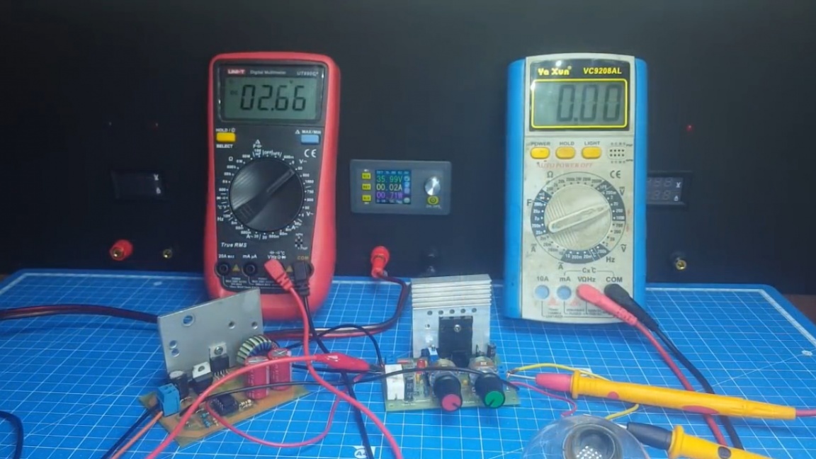
Then we catch the load (36V bulb, 100W power) and see what happens.
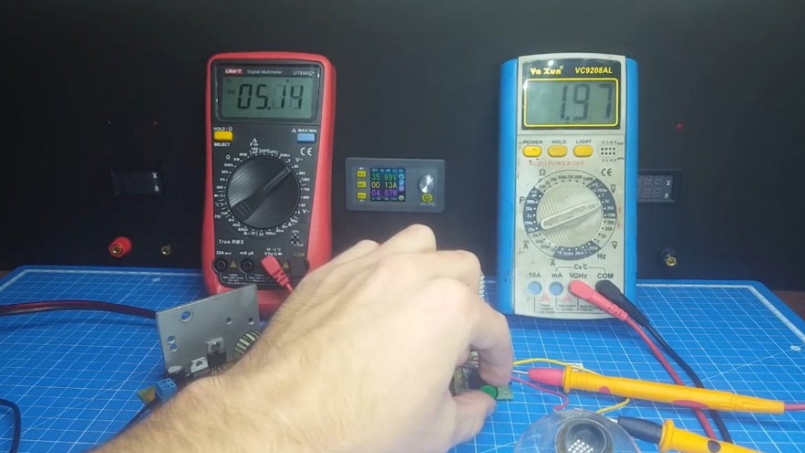
As you can see, when the output of the linear block 0, a voltage of about 2.8V is held at the pulse generator. Now we rotate the variable resistor, increasing the voltage at the output of the linear block, and as you can see, the impulse responds to this and, in turn, increases the voltage at its output.
Yes, some non-linearity is noticeable here, since the adder resistors are poorly selected, but the author believes that this is not fatal. In his opinion, even such a circuit would be much more practical than an ordinary switch of windings. You don’t think, the author is not trying to say that the switch is a bad thing, there is simply a more interesting solution.
Well, that’s all. I hope you enjoyed this idea. Thank you for attention. See you soon!
Video: