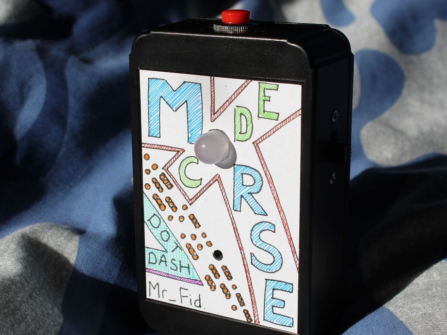
Readers know scouts - analogues of our pioneers, but it turns out that there are also cubs - analogues of our October. Accepted in them from the age of five. The son of the author Instructsbles under the nickname mr_fid has already been adopted, and he will have to attend a major event for cabs and scouts, one of which will be Morse code. To further interest the child, the master gave him an unusual toy.
It is executed on
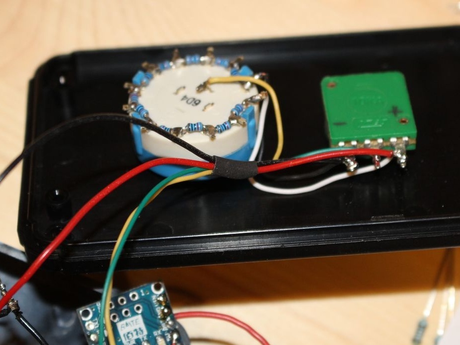
Arduino Nano also generates 12 different words output to the beeper with a built-in generator (switchable by a mechanical switch) and an RGB LED. The cycle can be adjusted between 100 and 1100 milliseconds. To switch words, a tinker switch is provided. The design is powered by a 1000 mAh lithium-polymer battery. The charge controller is built-in. But here it is not yet:
Mr_fid thanks Simon Monk for the book Arduino Programming, which he bought several years ago. In drawing up the sketch, he relied on examples from this book.
Starting work on
homemade, the master knew about Morse code only that there was an SOS signal. I had to learn the materiel and find out that the point is one measure, the dash is three, the interval between the characters in the letter is one measure, between the letters is three, between the words is seven.
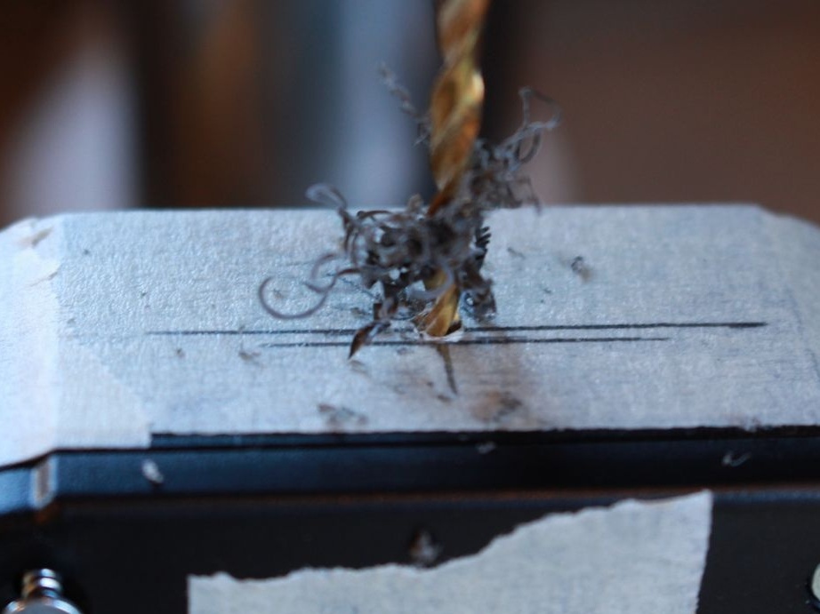
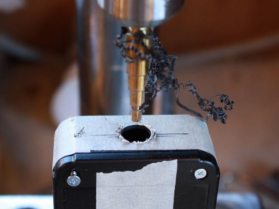
When marking plastic mr_fid uses masking tape. Thanks to this, the marker trace is better seen if the plastic is dark. In addition, this adhesive tape is matte, and the drill does not slip when “aiming”.
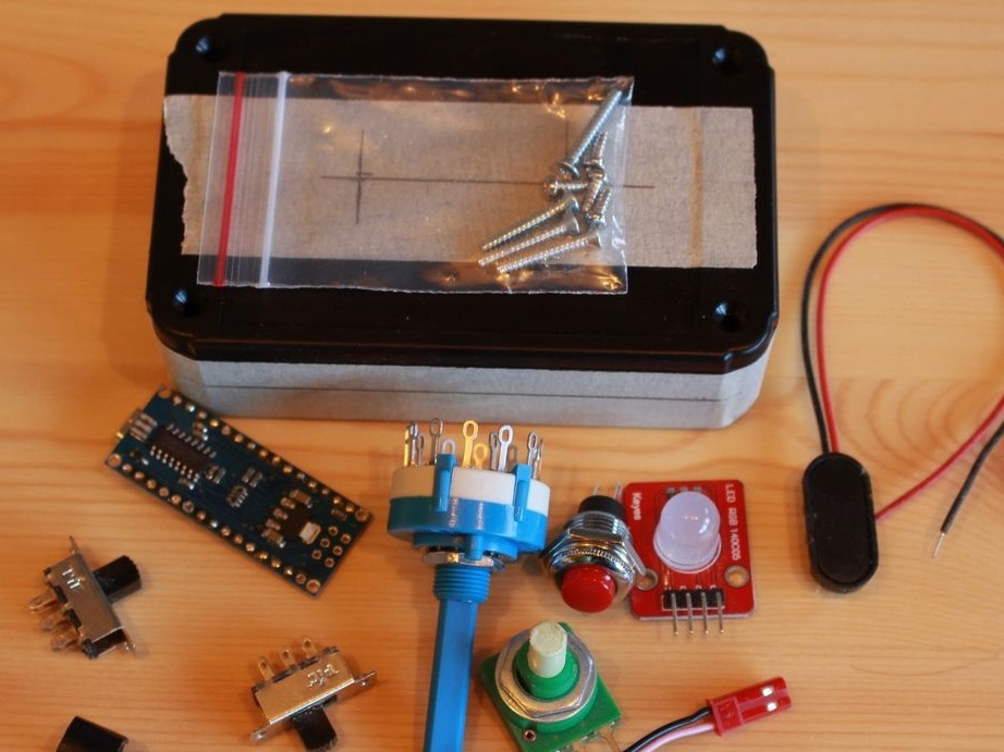
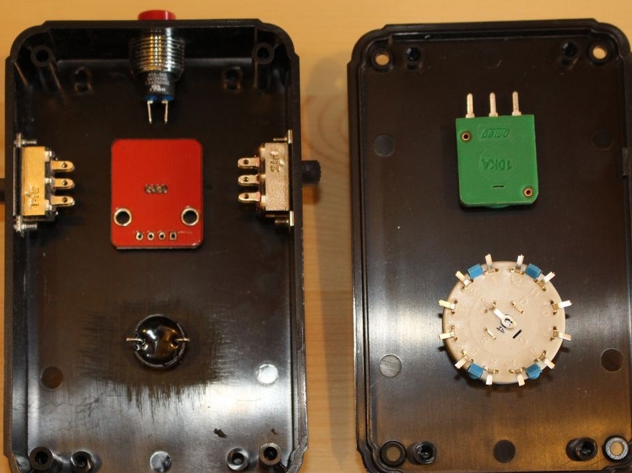
It is necessary to estimate in advance where which of the components of the structure will be located, so that everything fits, and not one of the components touches the neighboring ones, including the protruding parts. Mr_fid has not forgotten anything but ... the battery. Well, the case is quite spacious, and then a place for it was found. In the meantime ...
Although the master has a small bench drill, even with it he used a step drill for convenience, it is also a “herringbone” or “carrot”.
When the knob switch shaft is rotated by the handle, the switch itself must remain stationary. For this, in addition to the shaft, in front of it is a small pin that requires an additional hole on the front panel.
Therefore, mr_fid first drilled a hole for the shaft, then glued the masking tape on the back, put the wrench switch in place and pressed it. The pin left a mark on the masking tape, it remains to drill a hole there.
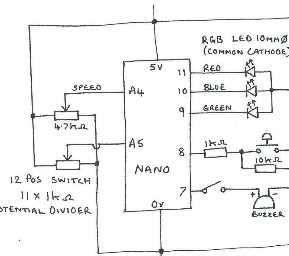
The scheme without taking into account the battery, charge controller and converter looks like this:
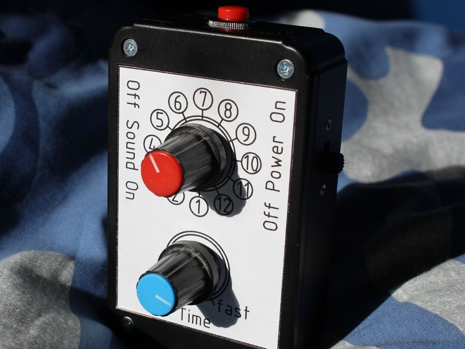
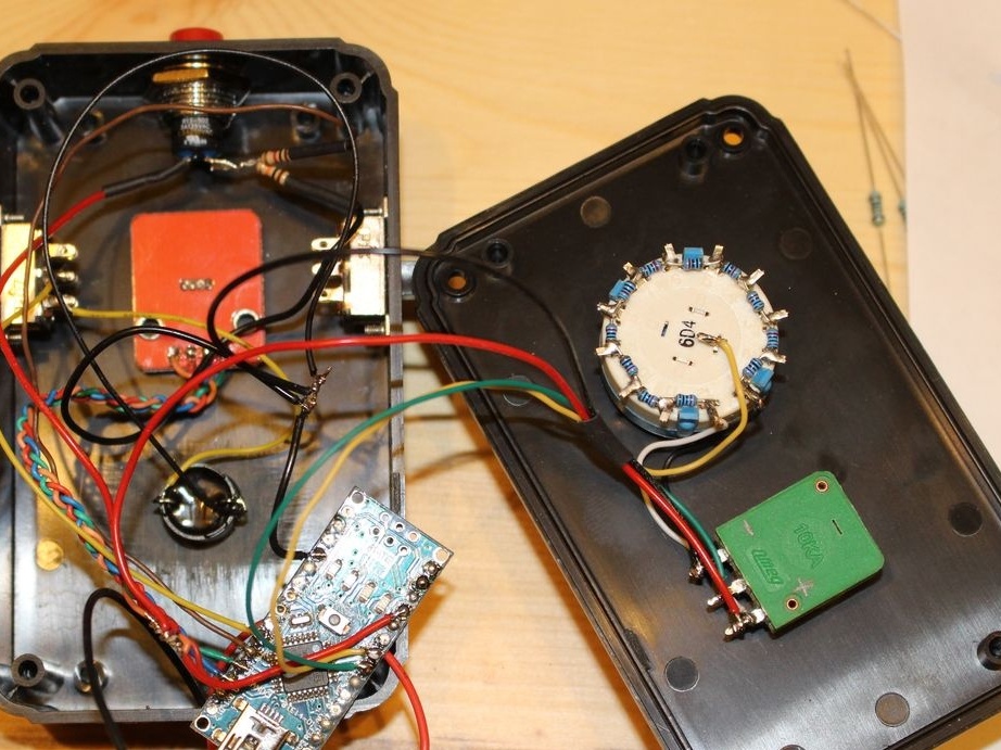
On the front panel, where the biscuit switch and the variable resistor are located, the master combined those conclusions of these components that are connected to the same points of the circuit in the case (in this case, the plus and the common wire). This allowed only four wires to be drawn between the front panel and the housing.
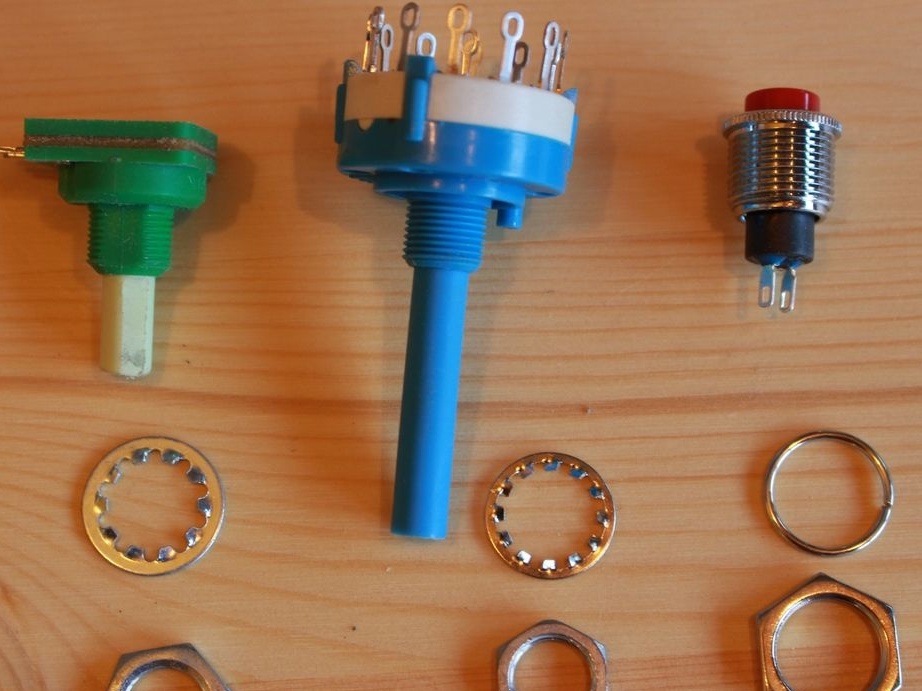
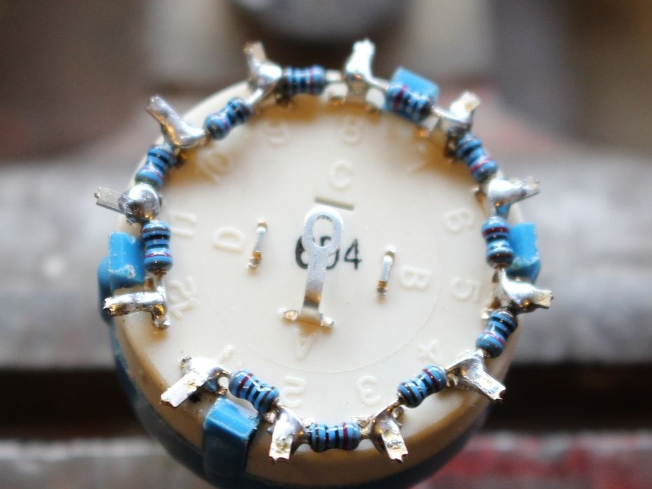
The wrench switch is also turned into a kind of variable resistor, only a step one, for which 11 resistors per 1 kOhm are soldered to it, as shown in the photographs. Arduino determines its position by a stepwise changing voltage, for which one analog input is enough.
Larger:
To control the RGB LED, mr_fid chose the Arduino pins with numbers 9, 10 and 11. These are PWM outputs, which in the next firmware will make it possible to get more bits per color than three.
He connected a plus and a common wire in reverse polarity to a variable resistor, so that the minimum position corresponds to the cycle of maximum duration, that is, the minimum speed.
The example from Simon Monk’s textbook is simple and single-functional: it takes data coming in through the serial port and translates it into Morse code with a 200 millisecond cycle. Additional functions added by the wizard provide adjustment of the period depending on the voltage coming from the variable resistor engine, as well as the refusal of the serial port in favor of storing 12 fixed words selected by the dial switch. Also added routines for controlling the RGB-LED mode switching button, well, and with a tweeter with a built-in generator, the program could control initially.
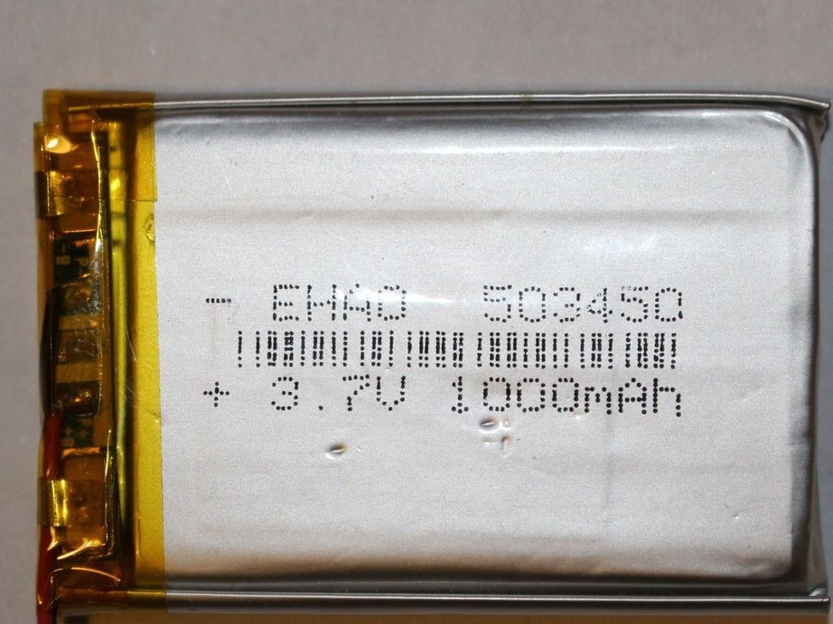
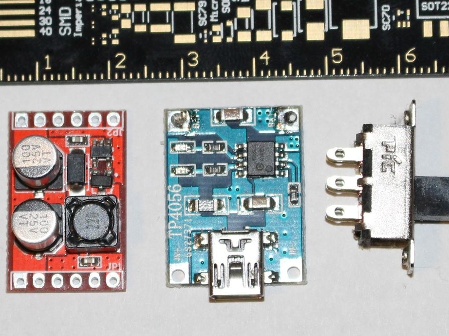
When programming Arduino, mr_fid completely forgot that the toy needs to be fed from something, because the board has been powered from USB all this time. When he remembered, the first thought was to power it all from the “Krona” through the stabilizer. But it did not fit, and at first the master wanted to place it outside, but then decided to use a thin lithium-polymer battery with 3.7 V and 1000 mAh.
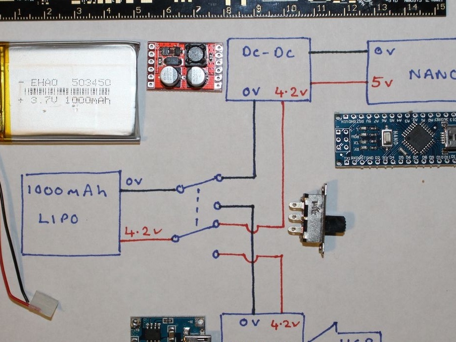
With a freshly charged battery, the voltage reaches 4.2 V, which is enough for all the crystals of the RGB LED, including blue. But as it discharges, it drops, and although 3.3 V is enough, the brightness of blue light can greatly decrease. I had to use a boost stabilizer with a stable five volts at the output. And in order not to remove the battery from the case when charging, the author added a charge controller and a two-pole reversing switch that connects the battery with both poles to either the Arduino or this controller. Now you can charge the toy from USB.
He connected all this together in such a way, not forgetting the polarity and the prevention of short-circuit:
By changing the position of the biscuit switch, you can select the Morse code for the following letter combinations: HHH (one dots), OOO (one dash), CAT (cat), DOG (dog), ANT (ant), FLY (fly), RAT (rat), OWL (owl), PIG (pig), HEN (chicken), FOX (fox) and EMU (emu). The button allows you to switch the operating modes of the RGB LED on the ring: constant colors - red, blue, green, blue-green, yellow, raspberry, white, as well as a red dot and a green dash, color change after each word, color change after each letter .
In Arduino, mr_fid uploaded such a sketch:int dotDelay = 200;
int ledPinRed = 11; // red
int ledPinBlue = 10; // blue
int ledPinGreen = 9; // green
int oldAI = 15;
int pat;
int i = 1;
int j = 0;
bool toggle = false;
int button = 8;
int buzzer = 7;
int flag = 1;
int selectWord;
int animal = 1;
int potValue = 0;
int maxVoltageBits = 1023;
int dividedBits = maxVoltageBits / 22;
const int pot = A4;
const int rotaryInput = A5;
char ch;
char * letters [] = {
".-", "-...", "-.-.", "- ..", ".", "..-.", "-.", "....", " .. ",
".---", "-.-", ".- ..", "-", "-.", "---", ".--.", "--.-", ".-.",
"...", "-", "..-", "...-", ".--", "-..-", "-.--", "- .."} ;
char * numbers [] = {
"-----", ".----", "..---", "...--", "....-",
".....", "-....", "--...", "--- ..", "----."};
char * animals3 = "hhhooocatdogantflyratowlpighenfoxemu";
void setup ()
{
pinMode (ledPinBlue, OUTPUT);
pinMode (ledPinRed, OUTPUT);
pinMode (ledPinGreen, OUTPUT);
pinMode (pot, INPUT);
pinMode (rotaryInput, INPUT);
pinMode (button, INPUT);
pinMode (buzzer, OUTPUT);
digitalWrite (ledPinRed, HIGH);
digitalWrite (ledPinBlue, HIGH);
digitalWrite (ledPinGreen, HIGH);
digitalWrite (ledPinRed, LOW);
delay (500);
digitalWrite (ledPinRed, HIGH);
delay (100);
digitalWrite (ledPinBlue, LOW);
delay (500);
digitalWrite (ledPinBlue, HIGH);
delay (100);
digitalWrite (ledPinGreen, LOW);
delay (500);
digitalWrite (ledPinGreen, HIGH);
delay (100);
digitalWrite (buzzer, HIGH);
delay (100);
digitalWrite (buzzer, LOW);
int buttonValue = digitalRead (button);
if (buttonValue == 1)
{
selectWord = analogRead (rotaryInput);
selectorSwitch1 (selectWord);
}
else
{
flag = 1;
}
}
void loop ()
{
wait_for_enter ();
selectWord = analogRead (rotaryInput);
selectorSwitch (selectWord);
potValue = analogRead (pot);
dotDelay = potValue + 100;
i = (animal * 3) -3;
while (j & lt; 3)
{
ch = animals3 [i];
if (ch & gt; = 'a' && ch & lt; = 'z')
{
flashSequence (letters [ch - 'a']);
}
else if (ch & gt; = '0' && ch & lt; = '9')
{
flashSequence (letters [ch - '0']);
}
else if (ch == '')
{
delay (dotDelay * 7);
}
i = i + 1;
j = j + 1;
}
delay (dotDelay * 7);
// toggle =! toggle; // toggle color every word (not needed)
j is 0;
}
void wait_for_enter ()
{
int buttonValue = digitalRead (button);
while (buttonValue == 0)
{
buttonValue = digitalRead (button);
}
}
void flashSequence (char * sequence)
{
int k = 0;
while (sequence [k]! = '\ 0')
{
flashDotOrDash (sequence [k]);
k = k + 1;
}
//Serial.print ("");
delay (dotDelay * 3);
toggle =! toggle; // toggle color beween letters
}
void flashDotOrDash (char dotOrDash)
{
if (dotOrDash == '.')
{
if (flag == 1)
{
digitalWrite (ledPinRed, LOW);
digitalWrite (buzzer, HIGH);
delay (dotDelay);
digitalWrite (buzzer, LOW);
digitalWrite (ledPinRed, HIGH);
}
else if (flag == 2)
{
digitalWrite (ledPinBlue, LOW);
digitalWrite (buzzer, HIGH);
delay (dotDelay);
digitalWrite (buzzer, LOW);
digitalWrite (ledPinBlue, HIGH);
}
else if (flag == 3)
{
digitalWrite (ledPinGreen, LOW);
digitalWrite (buzzer, HIGH);
delay (dotDelay);
digitalWrite (buzzer, LOW);
digitalWrite (ledPinGreen, HIGH);
}
else if (flag == 4)
{
digitalWrite (ledPinGreen, LOW);
digitalWrite (ledPinBlue, LOW);
digitalWrite (buzzer, HIGH);
delay (dotDelay);
digitalWrite (buzzer, LOW);
digitalWrite (ledPinGreen, HIGH);
digitalWrite (ledPinBlue, HIGH);
}
else if (flag == 5)
{
digitalWrite (ledPinRed, LOW);
digitalWrite (ledPinGreen, LOW);
digitalWrite (buzzer, HIGH);
delay (dotDelay);
digitalWrite (buzzer, LOW);
digitalWrite (ledPinRed, HIGH);
digitalWrite (ledPinGreen, HIGH);
}
else if (flag == 6)
{
digitalWrite (ledPinRed, LOW);
digitalWrite (ledPinBlue, LOW);
digitalWrite (buzzer, HIGH);
delay (dotDelay);
digitalWrite (buzzer, LOW);
digitalWrite (ledPinRed, HIGH);
digitalWrite (ledPinBlue, HIGH);
}
else if (flag == 7)
{
digitalWrite (ledPinRed, LOW);
digitalWrite (ledPinBlue, LOW);
digitalWrite (ledPinGreen, LOW);
digitalWrite (buzzer, HIGH);
delay (dotDelay);
digitalWrite (buzzer, LOW);
digitalWrite (ledPinRed, HIGH);
digitalWrite (ledPinBlue, HIGH);
digitalWrite (ledPinGreen, HIGH);
}
else if (flag == 8)
{
digitalWrite (ledPinRed, LOW);
digitalWrite (buzzer, HIGH);
delay (dotDelay);
digitalWrite (buzzer, LOW);
digitalWrite (ledPinRed, HIGH);
}
else if (flag == 9)
{
if (toggle! = 0)
{
digitalWrite (ledPinRed, LOW);
digitalWrite (buzzer, HIGH);
delay (dotDelay);
digitalWrite (buzzer, LOW);
digitalWrite (ledPinRed, HIGH);
}
else
{
digitalWrite (ledPinBlue, LOW);
digitalWrite (buzzer, HIGH);
delay (dotDelay);
digitalWrite (buzzer, LOW);
digitalWrite (ledPinBlue, HIGH);
}
}
}
else
{
if (flag == 1)
{
digitalWrite (ledPinRed, LOW);
digitalWrite (buzzer, HIGH);
delay (dotDelay * 3);
digitalWrite (buzzer, LOW);
digitalWrite (ledPinRed, HIGH);
}
else if (flag == 2)
{
digitalWrite (ledPinBlue, LOW);
digitalWrite (buzzer, HIGH);
delay (dotDelay * 3);
digitalWrite (buzzer, LOW);
digitalWrite (ledPinBlue, HIGH);
}
else if (flag == 3)
{
digitalWrite (ledPinGreen, LOW);
digitalWrite (buzzer, HIGH);
delay (dotDelay * 3);
digitalWrite (buzzer, LOW);
digitalWrite (ledPinGreen, HIGH);
}
else if (flag == 4)
{
digitalWrite (ledPinGreen, LOW);
digitalWrite (ledPinBlue, LOW);
digitalWrite (buzzer, HIGH);
delay (dotDelay * 3);
digitalWrite (buzzer, LOW);
digitalWrite (ledPinGreen, HIGH);
digitalWrite (ledPinBlue, HIGH);
}
else if (flag == 5)
{
digitalWrite (ledPinRed, LOW);
digitalWrite (ledPinGreen, LOW);
digitalWrite (buzzer, HIGH);
delay (dotDelay * 3);
digitalWrite (buzzer, LOW);
digitalWrite (ledPinRed, HIGH);
digitalWrite (ledPinGreen, HIGH);
}
else if (flag == 6)
{
digitalWrite (ledPinRed, LOW);
digitalWrite (ledPinBlue, LOW);
digitalWrite (buzzer, HIGH);
delay (dotDelay * 3);
digitalWrite (buzzer, LOW);
digitalWrite (ledPinRed, HIGH);
digitalWrite (ledPinBlue, HIGH);
}
else if (flag == 7)
{
digitalWrite (ledPinRed, LOW);
digitalWrite (ledPinBlue, LOW);
digitalWrite (ledPinGreen, LOW);
digitalWrite (buzzer, HIGH);
delay (dotDelay * 3);
digitalWrite (buzzer, LOW);
digitalWrite (ledPinRed, HIGH);
digitalWrite (ledPinBlue, HIGH);
digitalWrite (ledPinGreen, HIGH);
}
else if (flag == 8)
{
digitalWrite (ledPinGreen, LOW);
digitalWrite (buzzer, HIGH);
delay (dotDelay * 3);
digitalWrite (buzzer, LOW);
digitalWrite (ledPinGreen, HIGH);
}
else if (flag == 9)
{
if (toggle! = 0)
{
digitalWrite (ledPinRed, LOW);
digitalWrite (buzzer, HIGH);
delay (dotDelay * 3);
digitalWrite (buzzer, LOW);
digitalWrite (ledPinRed, HIGH);
}
else
{
digitalWrite (ledPinBlue, LOW);
digitalWrite (buzzer, HIGH);
delay (dotDelay * 3);
digitalWrite (buzzer, LOW);
digitalWrite (ledPinBlue, HIGH);
}
}
}
delay (dotDelay); // between letters
// toggle =! toggle; // toggle between caractors
}
void selectorSwitch1 (int AI)
{
if ((AI & gt; (oldAI + 10)) || (AI & lt; (oldAI - 10))) // see if the value has changed?
{
if (AI & gt; 11 * dividedBits) // must be 7,8,9,10,11,12.
{
if (AI & gt; 17 * dividedBits) // must be 10,11,12.
{
if (AI & gt; 21 * dividedBits) // must be 12.
{
flag = 12;
}
else // must be either 10.11.
{
if (AI & gt; 19 * dividedBits) // must be 11.
{
flag = 11;
}
else // must be 10.
{
flag = 10;
}
}
}
else // must be 7,8,9.
{
if (AI & gt; 15 * dividedBits) // must be 9.
{
flag = 9;
}
else // must be 7.8.
{
if (AI & gt; 13 * dividedBits) // must be 8.
{
flag = 8;
}
else // must be 7.
{
flag = 7;
}
}
}
}
else // must be 1,2,3,4,5,6.
{
if (AI & gt; 5 * dividedBits) // must be 4,5,6.
{
if (AI & gt; 9 * dividedBits) // must be 6.
{
flag = 6;
}
else // must be 4,5.
{
if (AI & gt; 7 * dividedBits) // must be 5
{
flag = 5;
}
else // must be 4.
{
flag = 4;
}
}
}
else // must be 1,2,3.
{
if (AI & gt; 3 * dividedBits) // must be 3.
{
flag = 3;
}
else // must be 1,2.
{
if (AI & gt; dividedBits) // must be 2.
{
flag = 2;
}
else // must be 1.
{
flag = 1;
}
}
}
}
}
oldAI = AI;
// delay (500);
//Serial.println ();
}
void selectorSwitch (int AI)
{
if ((AI & gt; (oldAI + 10)) || (AI & lt; (oldAI - 10))) // see if the value has changed?
{
if (AI & gt; 11 * dividedBits) // must be 7,8,9,10,11,12.
{
if (AI & gt; 17 * dividedBits) // must be 10,11,12.
{
if (AI & gt; 21 * dividedBits) // must be 12.
{
animal = 12;
}
else // must be either 10.11.
{
if (AI & gt; 19 * dividedBits) // must be 11.
{
animal = 11;
}
else // must be 10.
{
animal = 10;
}
}
}
else // must be 7,8,9.
{
if (AI & gt; 15 * dividedBits) // must be 9.
{
animal = 9;
}
else // must be 7.8.
{
if (AI & gt; 13 * dividedBits) // must be 8.
{
animal = 8;
}
else // must be 7.
{
animal = 7;
}
}
}
}
else // must be 1,2,3,4,5,6.
{
if (AI & gt; 5 * dividedBits) // must be 4,5,6.
{
if (AI & gt; 9 * dividedBits) // must be 6.
{
animal = 6;
}
else // must be 4,5.
{
if (AI & gt; 7 * dividedBits) // must be 5
{
animal = 5;
}
else // must be 4.
{
animal = 4;
}
}
}
else // must be 1,2,3.
{
if (AI & gt; 3 * dividedBits) // must be 3.
{
animal = 3;
}
else // must be 1,2.
{
if (AI & gt; dividedBits) // must be 2.
{
animal = 2;
}
else // must be 1.
{
animal = 1;
}
}
}
}
}
oldAI = AI;
// delay (500);
//Serial.println ();
}
If you repeated after the master, now in your hands is the same toy with which you can interest your children in Morse code. And when they grow up, with a simple firmware alteration, you can get the basis for a standard automatic "fox", transmitting a choice of MOE, MOI, MOS, MOH or MO5, turning on for one minute every four minutes.
P.S. especially for boring people who find fault with headlines: animals are a collective name for animals, birds and insects.