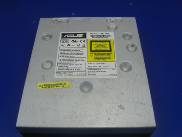
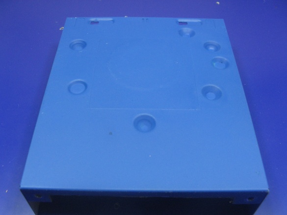
It so happened that for more than five years I have been using a 42 volt soldering iron. Since the soldering iron is low voltage, it must be powered from the appropriate voltage. Usually, such soldering irons are supplied with a step-down transformer. I do not have a transformer. All this time I have been feeding a soldering iron through a capacitor, or rather a battery connected in parallel. So I decided to make a new case, the old one was plastic, but it burst when it fell. I’ll install the capacitor in a convenient housing from the computer’s DVD drive.
About the scheme.
What is there to draw? A capacitor is connected in series with the soldering iron. Parallel to the capacitor, a discharge resistor. All.
For homemade we will need:
- housing from a DVD drive;
- toggle switch or switch;
- plastic sheet;
- MBGO capacitors;
- instruments.
About accessories.
The housing, as already mentioned, is the housing of the DVD drive. The old case is best suited. On the old case there are a lot of any bends that will interfere with the components placed in it. We remove the filling in the bins.
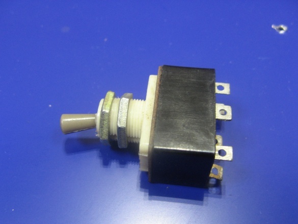
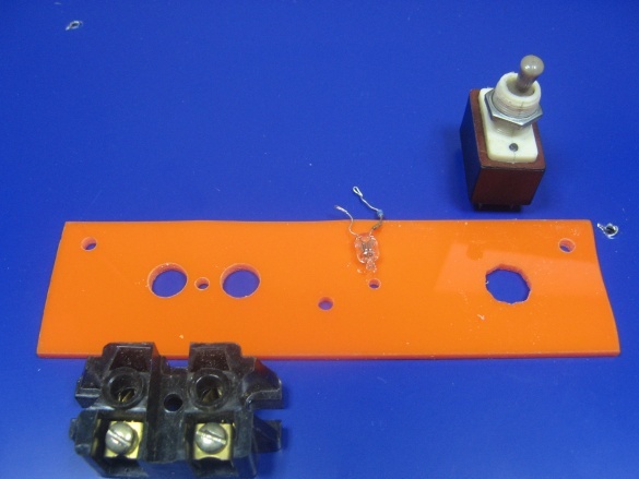
I have a T3 toggle switch. It is better to use a rocker switch, such as installed on computer power supplies. The rocker is more compact, but I didn’t have it.
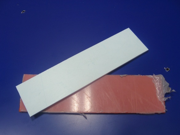
For the front panel, I took two types of plastic. The front will go more rigid plastic plexiglas. On the back I will use PVC plastic, it is softer. Immediately cut two segments, the size of the front and rear panels.
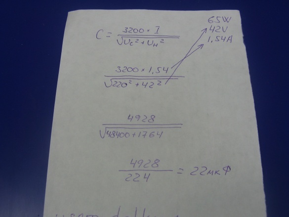
The calculation of the capacitor was made according to this formula. All clear. Soldering iron 65 watts, supply voltage 42V. The current turned out to be 1.54A. I applied this formula many times. It turned out 22 uF.
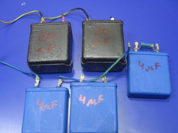
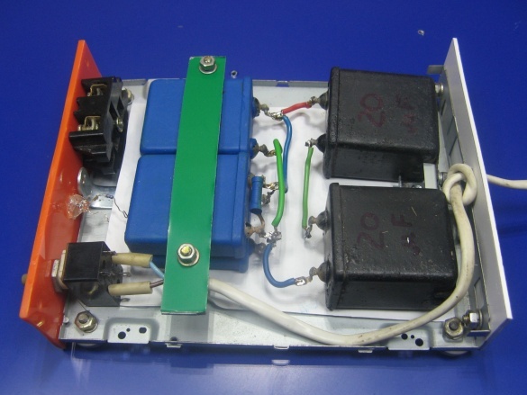
Capacitors I took MBGO. They rusted in my old building. I painted them in different colors. At 4 microfarads I have at 400V, not less. And two black ones, at 20 uF at 160V each. Blacks are included in series. The result is 10 microfarads and a voltage of more than 300V. There were no others, applied what is. As a result, 22 μF was obtained from all capacitors. On one of the capacitors, with an old design, a 470 kΩ discharge resistor is soldered.
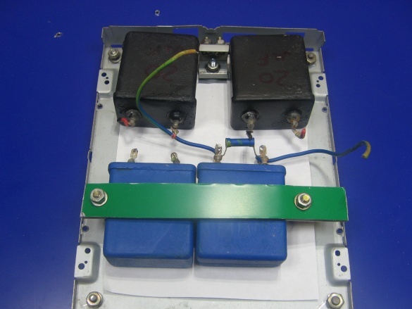
I fix the capacitors on the bottom of the DVD drive. Blue, just crushed by a strip of composite plastic.Black secured with a corner. Using the same corner and fastened them together. On capacitors there are "ears" of fastening. Holding perfectly
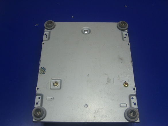
I screwed the rubber legs to the bottom of the case. They took them from the used bottles of Pinicillin, or rather the bottle cap.
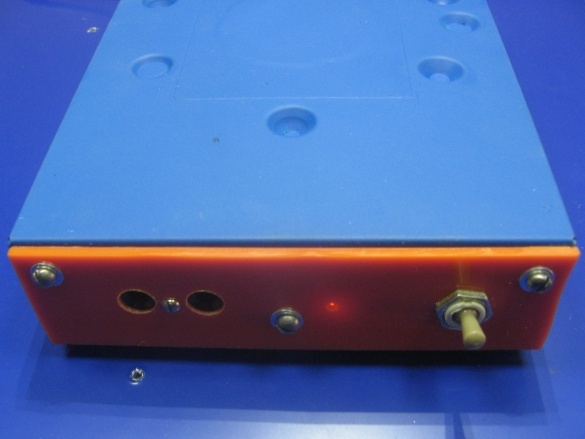
On the front panel I do the markup. I will drill holes for the toggle switch, socket and neon bulb. Instead of "neonka" you can install the LED, but I had what I installed. Also, on the panel blank, I drill holes for fasteners.
I am soldering capacitors. Installed a back panel with a power cord. The cord sealed on the toggle switch. Then I connect the wires to the socket. I am soldering a neon bulb. Also from the toggle switch to the capacitor. The photo was lost.
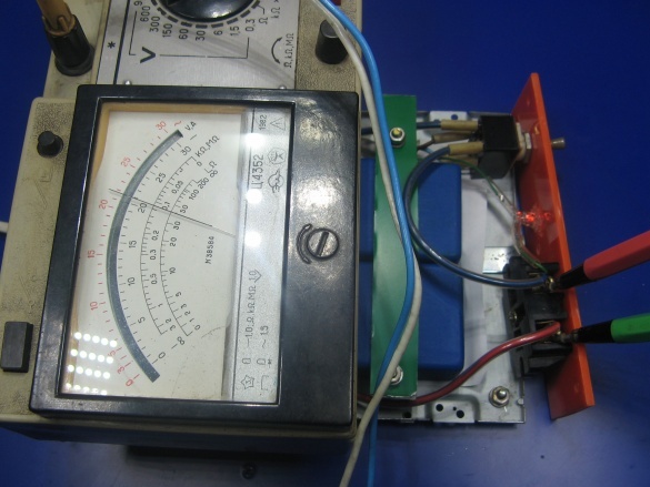
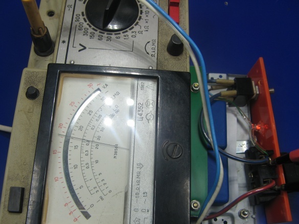
Now you need to test. Without a connected soldering iron, the voltage was 210 volts.
With a soldering iron it was about 35V. So I expected that the voltage will float slightly. The voltage does not go beyond 35-42V. It suits me.
The lid was painted from a spray can. For the outlet and toggle switch made a cutout grinder. The sticker from the case did not peel off. There is a disc guide under the sticker. If you remove it, you get a hole, but I do not need it.
I put on the lid and tighten the screws. Such a design turned out. Although the soldering iron is not galvanically isolated from the network, I successfully use it to solder any radio components. From memory, I recently soldered them capacitors on the motherboard. CMOS chips did not have to be soldered. For soldering stuff, I have a 25 watt soldering iron.
Video on the assembly of this power supply:


