
Today we will have fun with the address LED matrix. This project is quite complex, but at the same time everyone can repeat it. The author of the project is AlexGyver.
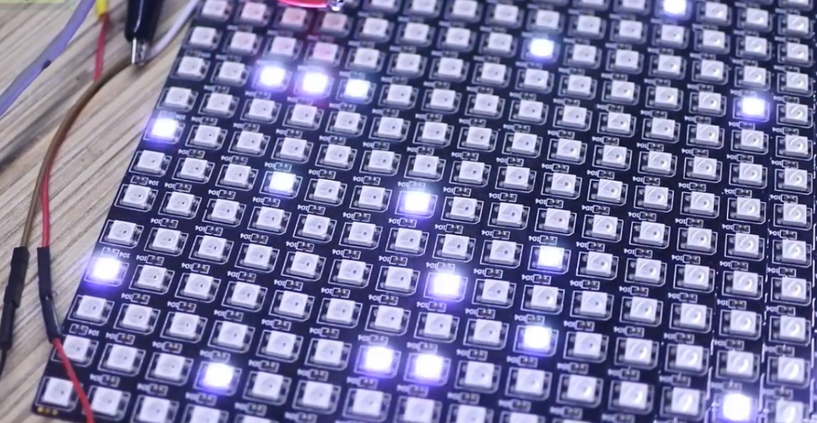
The address LED strip consists of three-color LEDs, each of which has a special microcircuit.
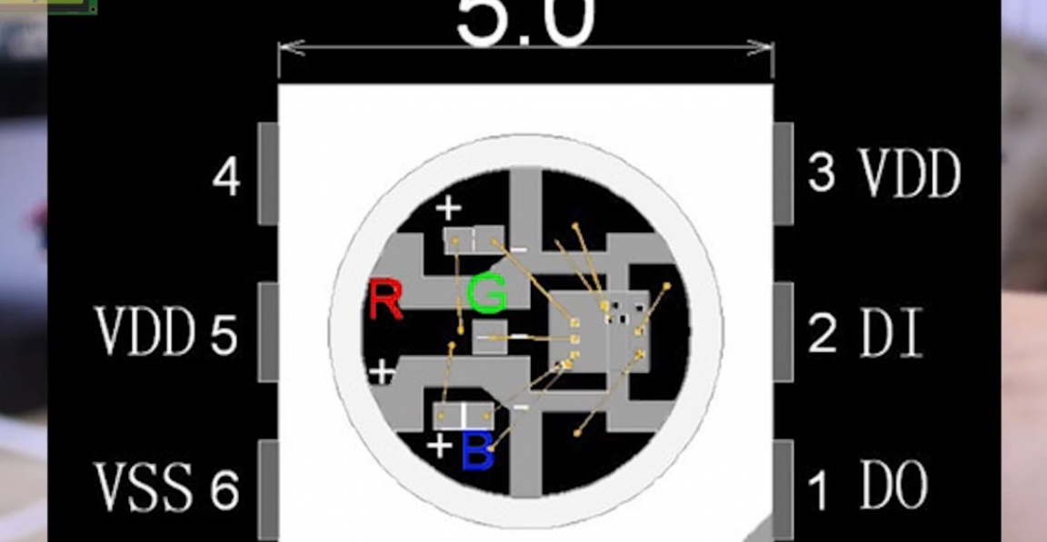
The microcircuit in the LEDs transmits information to each other. This allows you to light any LED on the tape in one of 16 million colors and shades. And the coolest thing is that this whole thing is managed on one wire, in a very interesting time we live.
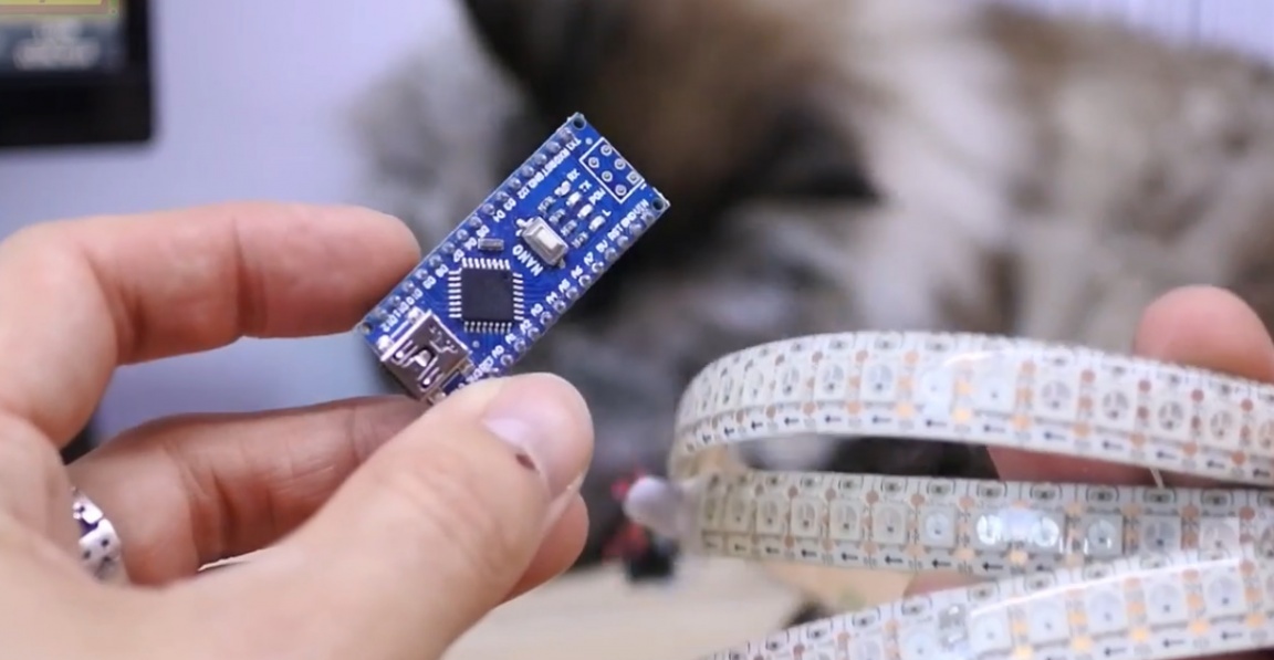
The tape is controlled by a microcontroller, for example, a platform arduino.
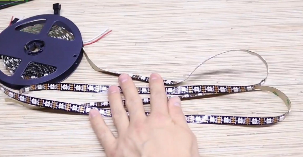
Such a bunch in itself is very interesting and you can find a bunch of applications in design or homemade products, which is worth only the flame effect. But today it’s not about that. What happens if the tape is laid in a zigzag pattern, and laid so that the LEDs form an even, regular grid? That's right, the LED matrix. For convenience, you can buy a finished matrix from the Chinese, and the most interesting is that it costs much less than buying a tape and spending several hours cutting and connecting the pieces with wires.
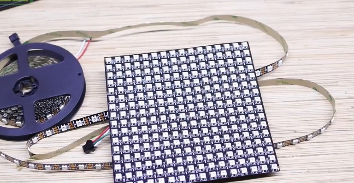
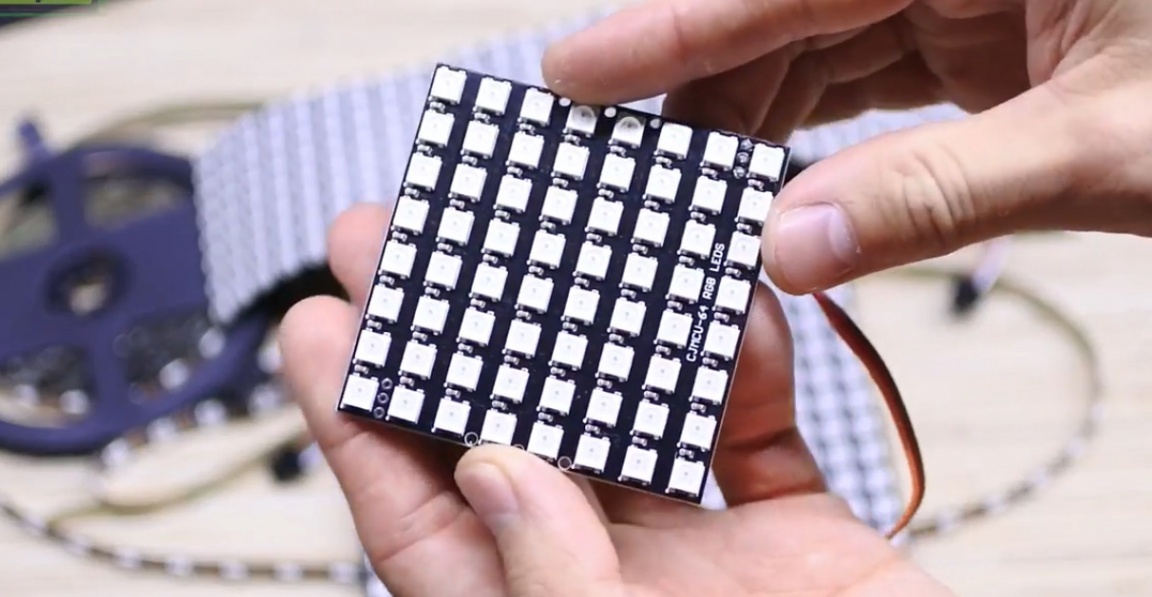
For example, there is such an 8X8 matrix, the cheapest, it will be easier for someone to play with it.
The feature of today's project is its versatility and versatility, that is, you can buy a ready-made matrix, but it is so to speak small, but you can also buy a tape with a low density of LEDs and make a matrix from it the size of, say, a picture. Now it will be cool.
The matrix presents very great opportunities for creating various pixel effects, outputting images and gifs (gifs), creating classic games and other interesting things. Be sure to visit project page, there you will find all the necessary links, firmware, diagrams and additional instructions.
So, armed with a matrix management tool, we are able to light any LED in its coordinates.
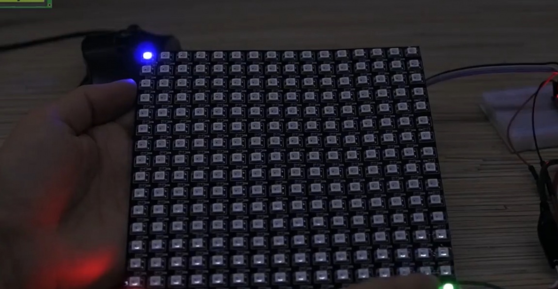
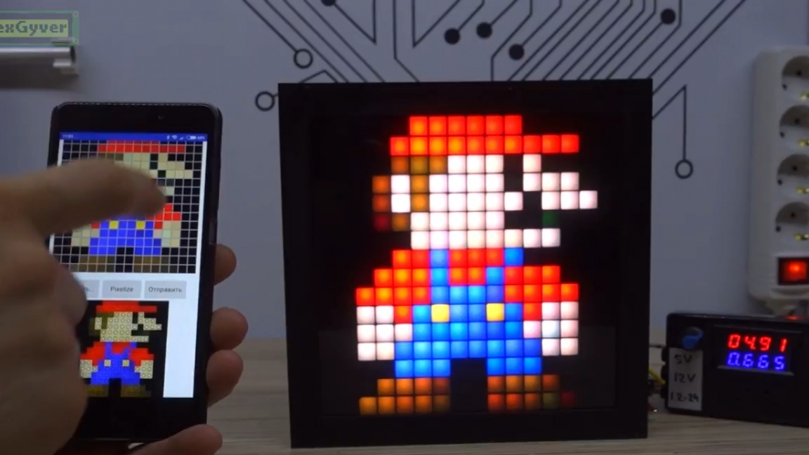
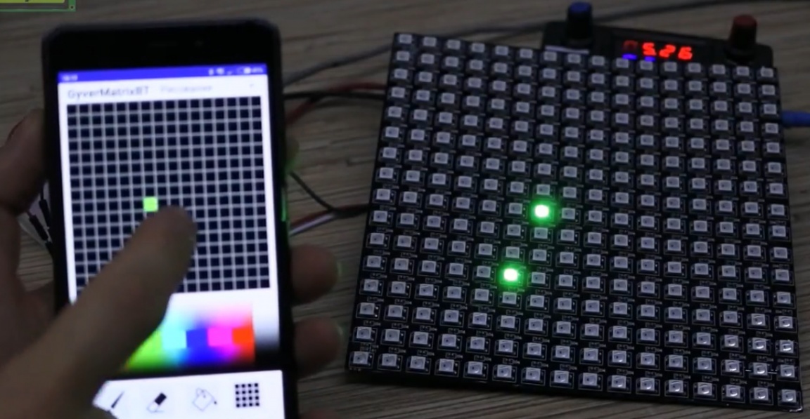
Great, you can do all sorts of cool effects. You can control from a smartphone via bluetooth. That is, the smartphone sends some commands via bluetooth, the module receives and transmits them to arduino. And arduino, in turn, outputs the data to the matrix.
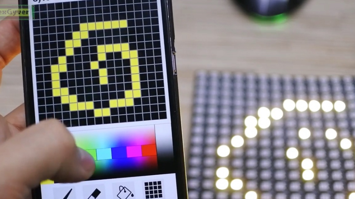
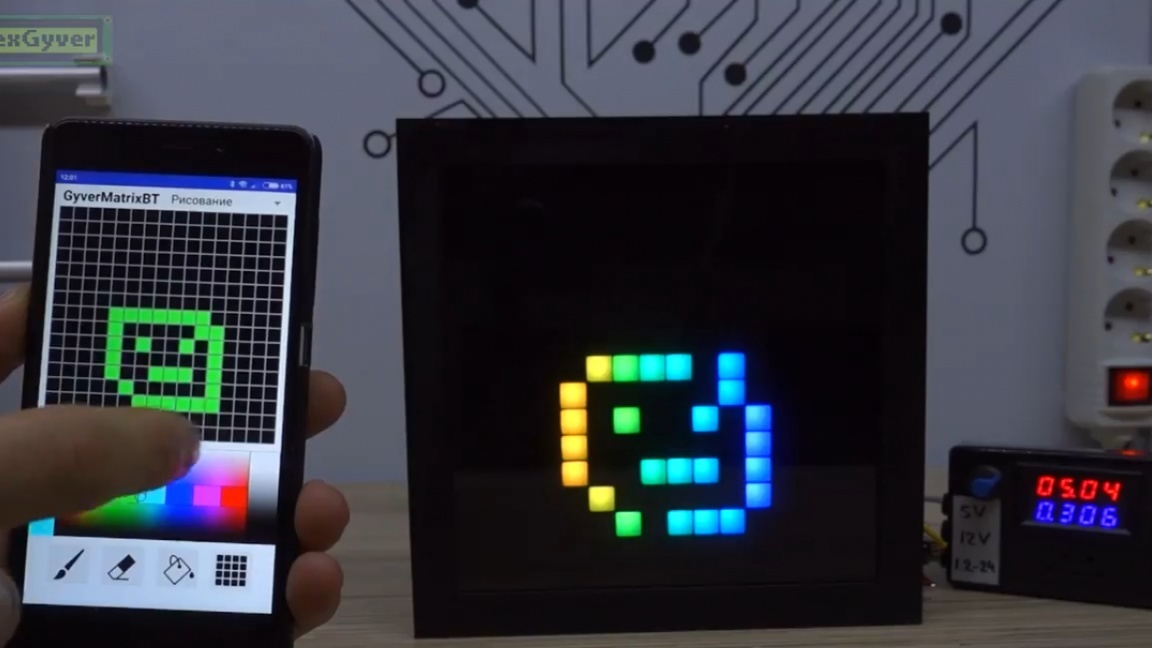
The author began with the fact that he decided to make a drawing, that is, so that you can choose a color and light up any LED on the matrix.
The first step was to develop a communication protocol with arduino.
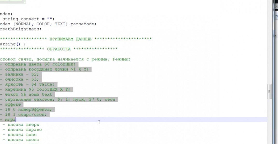
The first digit in it is the mode, and the rest were responsible for various settings and other transmitted values. Then the author made a graphic field on which he drew a grid.
The program tracks the coordinates of touching the field with a finger and draws a square in this place with any color. Along the way, the coordinates of the square are sent to arduino.
For the manufacture we need:
1) Matrix or tape on the address LEDs;
2) Arduino;
3) Bluetooth module;
4) Resistor.
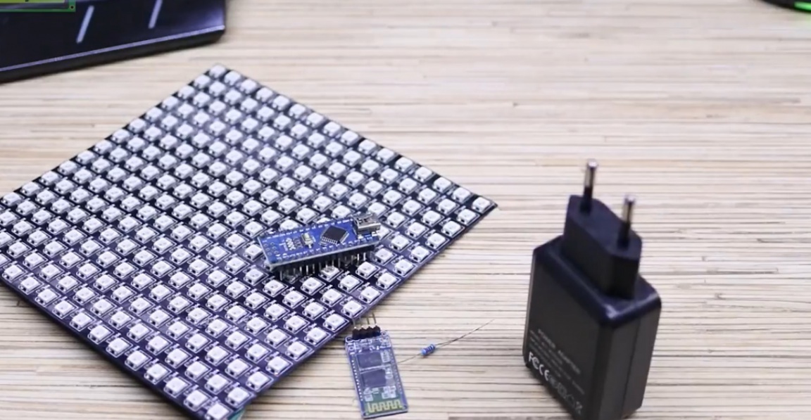
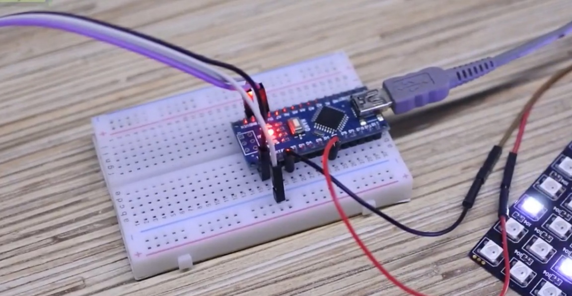
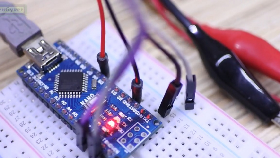
You can buy a pound from the Chinese, or you can buy at any radio store. We connect the components according to a very simple scheme:
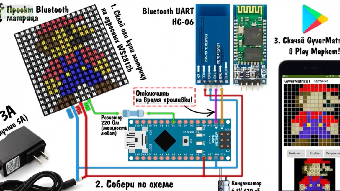
You can collect everything on a breadboard. Then download the archive with the project from the project page, install the libraries according to the instructions and open the file with the firmware.
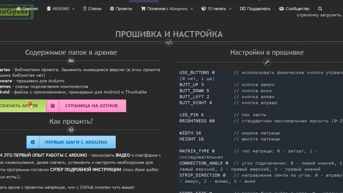
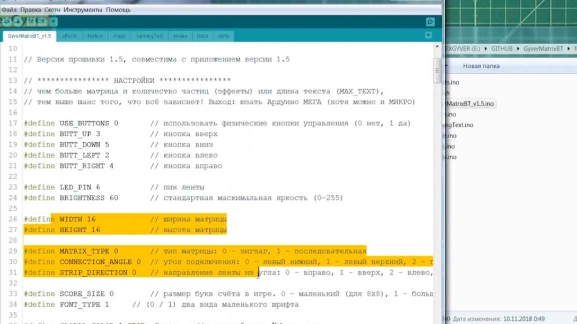
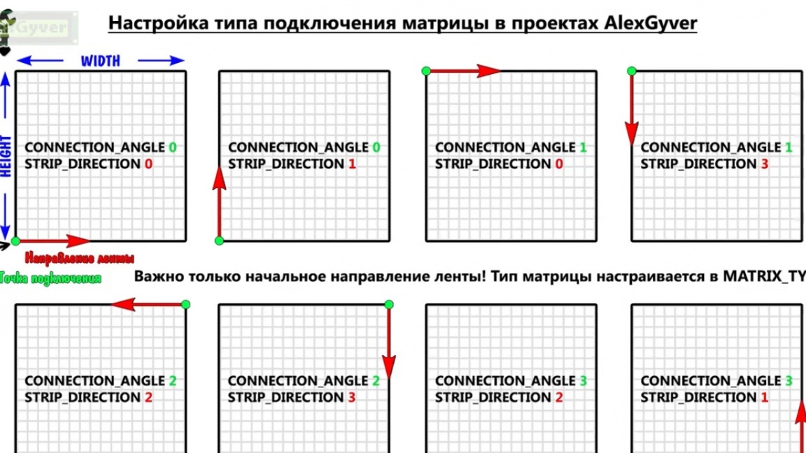
Here we have the settings. Indicate the size of your matrix, its type and connection point.
If you make a large matrix yourself, that is, solder from pieces of tape, then you have 2 types to choose from.
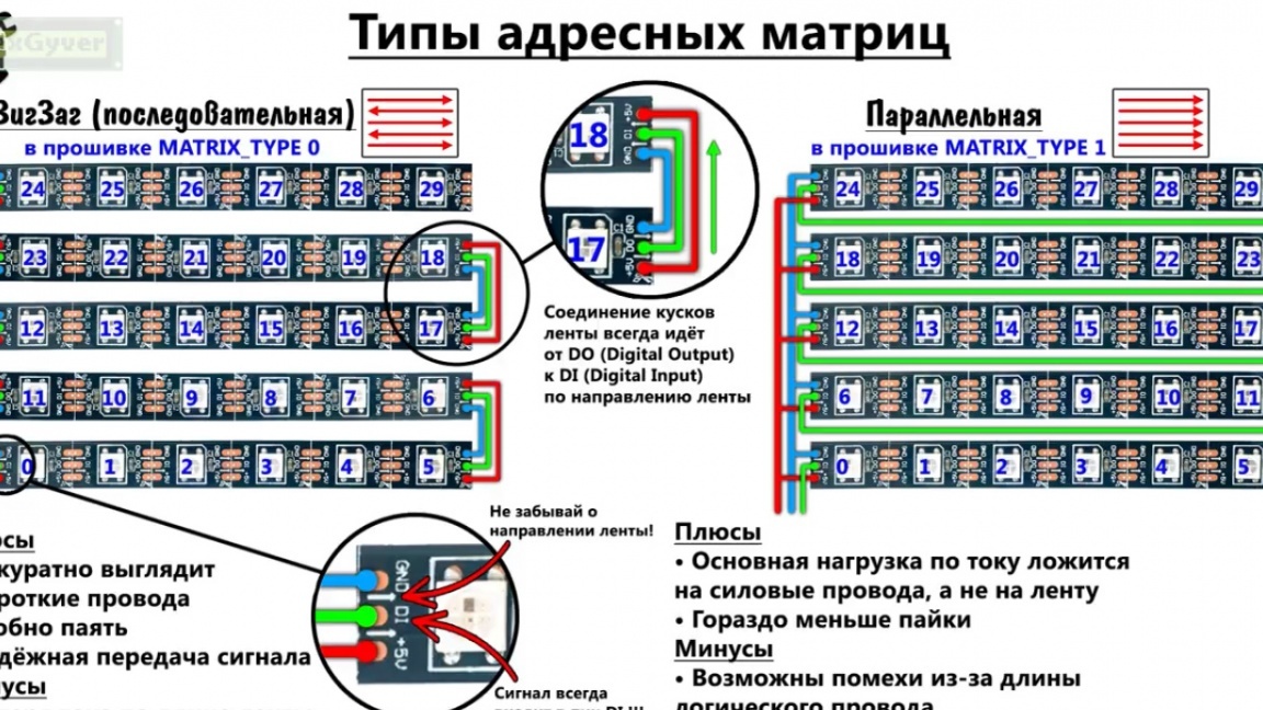
The author advises choosing the right option, since it is easier to solder. Now it remains to determine the beginning of the matrix, that is, the connection point to it and the direction of the first piece of tape. Such a cheat sheet will help for all 8 matrix layout options:
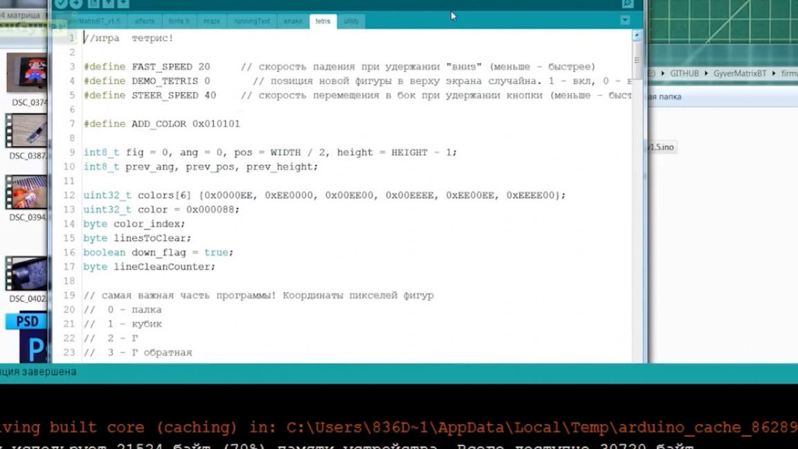
The author spent a lot of time on this firmware. This is the author’s largest project in terms of code. Arduino is packed just to the eyeballs, shoved as they say unbearable.
So, set up, click download firmware. Before downloading, you must definitely disconnect bluetooth from the rx pin, otherwise the arduino will not flash. For convenience, you can also solder a switch to the wire.
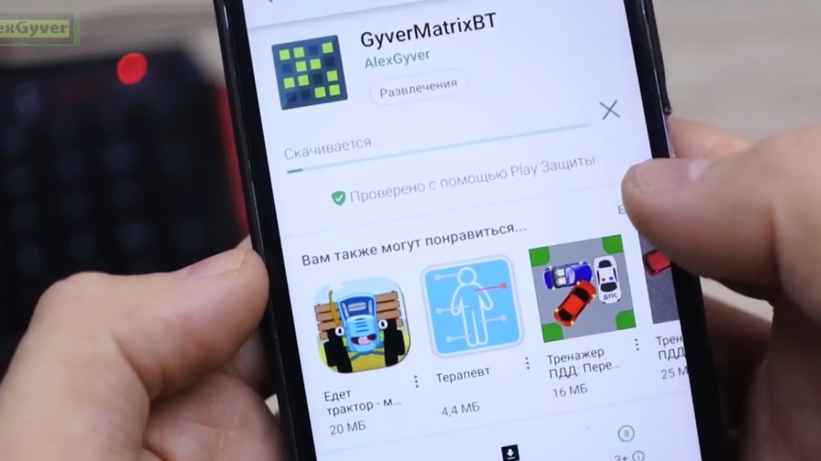
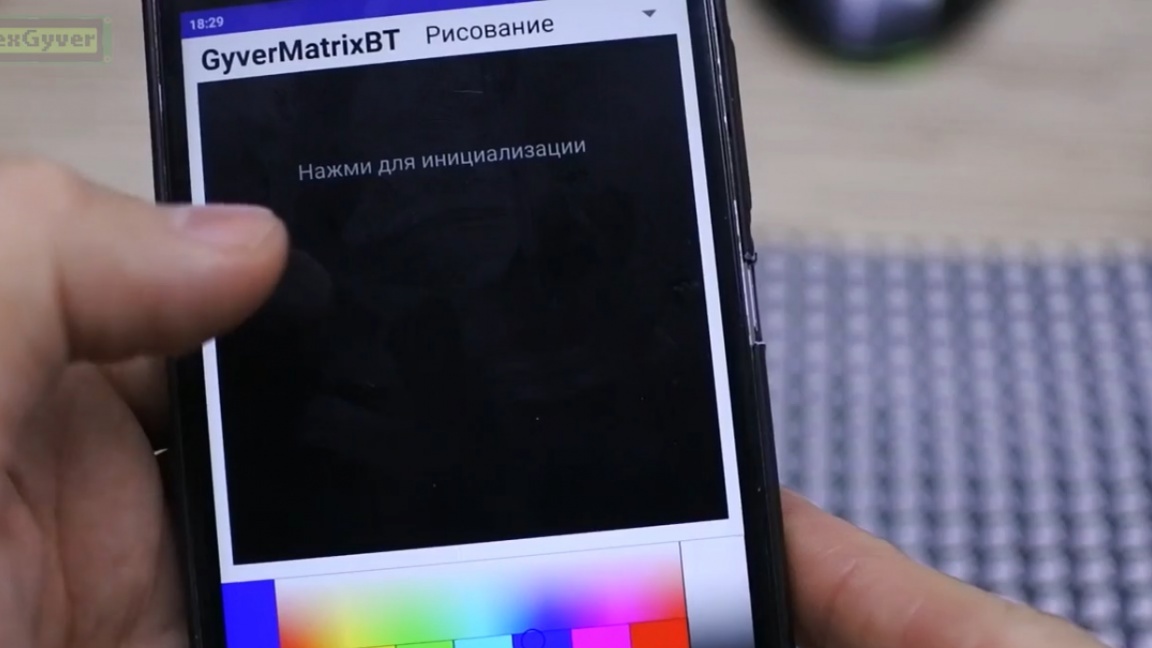
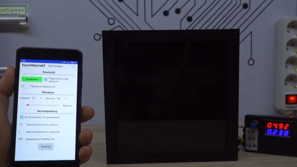
Next, on the smartphone running android, install the application GyverMatrixBT. This application is available on the Play Market, it is completely free and without ads.
Then pair with the bluetooth module (password 1234 or 0000), in the application connect to the module and, in fact, everything. In the settings, you can adjust the brightness and size of the matrix that matches yours, as well as some of its other parameters.
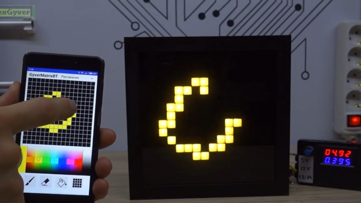
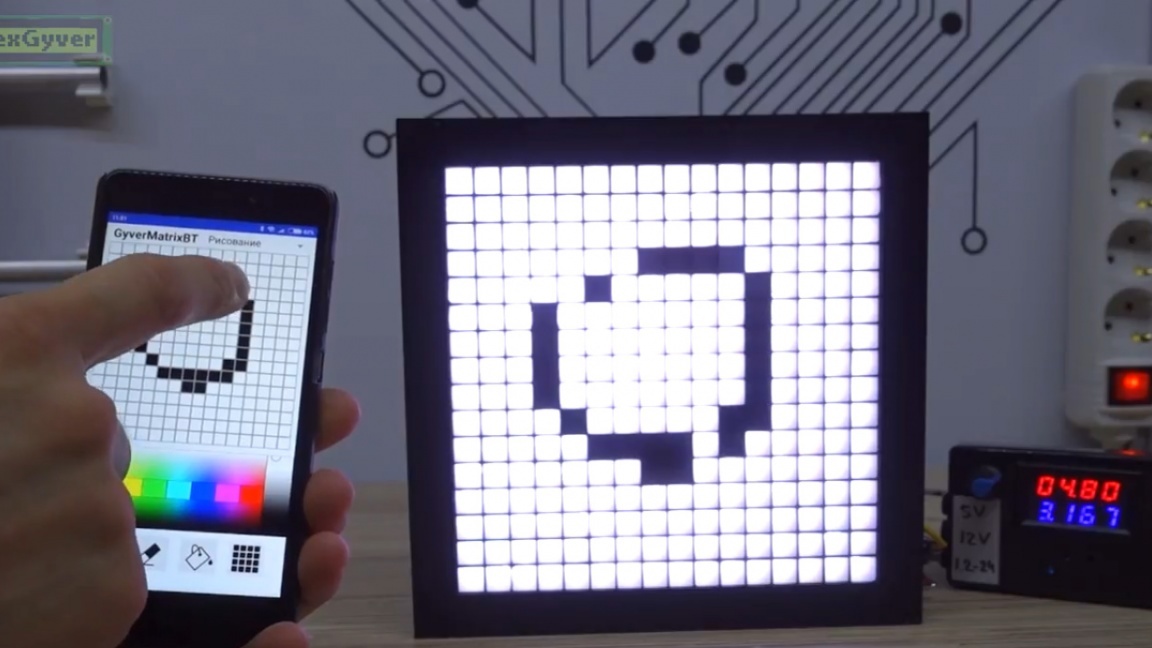
According to the adjusted size, in the drawing tab we will have a field. Click to initialize it. Here you can draw with tapes and swipe, you can erase, you can clear the field and fill it with color.
In general, at the moment we have a working tool for sending data to the matrix. You can move on. The whole system was conceived by the author in order to build a large matrix of tape or modules. This is interesting as a project, as a hobby, it can be useful to someone for advertising purposes, for design or for design, or for fun.
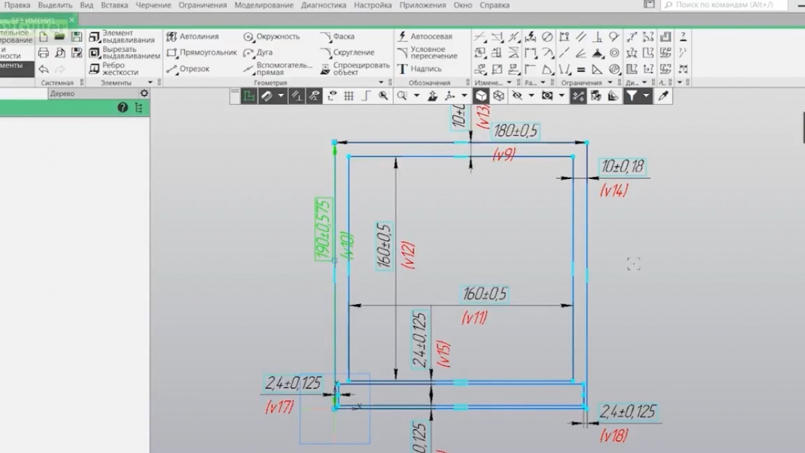
But the matrix in this form does not look very cool, not pixel and not eight-bit. It is necessary to make a lattice so that each LED forms its own square pixels and place a diffuser on top. Then everything will be very cool. The grill can be made of any material in the form and slats. It can be cardboard, a pack of Soviet wooden rulers or an option made of plastic (PVC corner), it can be bought at a building materials store where there are plastic panels and various goods for them. Corners can be broken along, made slots for the middle and assemble the grill. This is the most “collective farm” option after cardboard.
And of course you can relax and print the grille on a 3d printer. So let's do it.
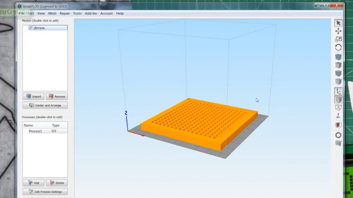
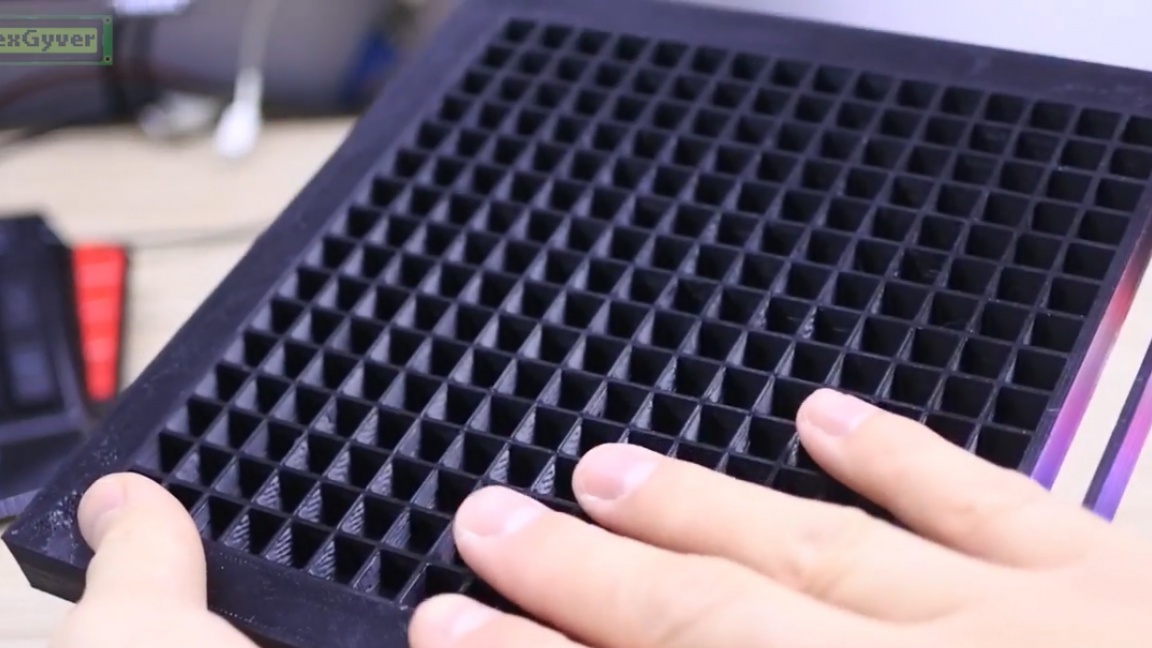
So, the matrix body printed. By the way, the author believes that black is not the best choice, it is better to print the grille in white so that it reflects the light. Well, it doesn’t matter, we’ll paint.
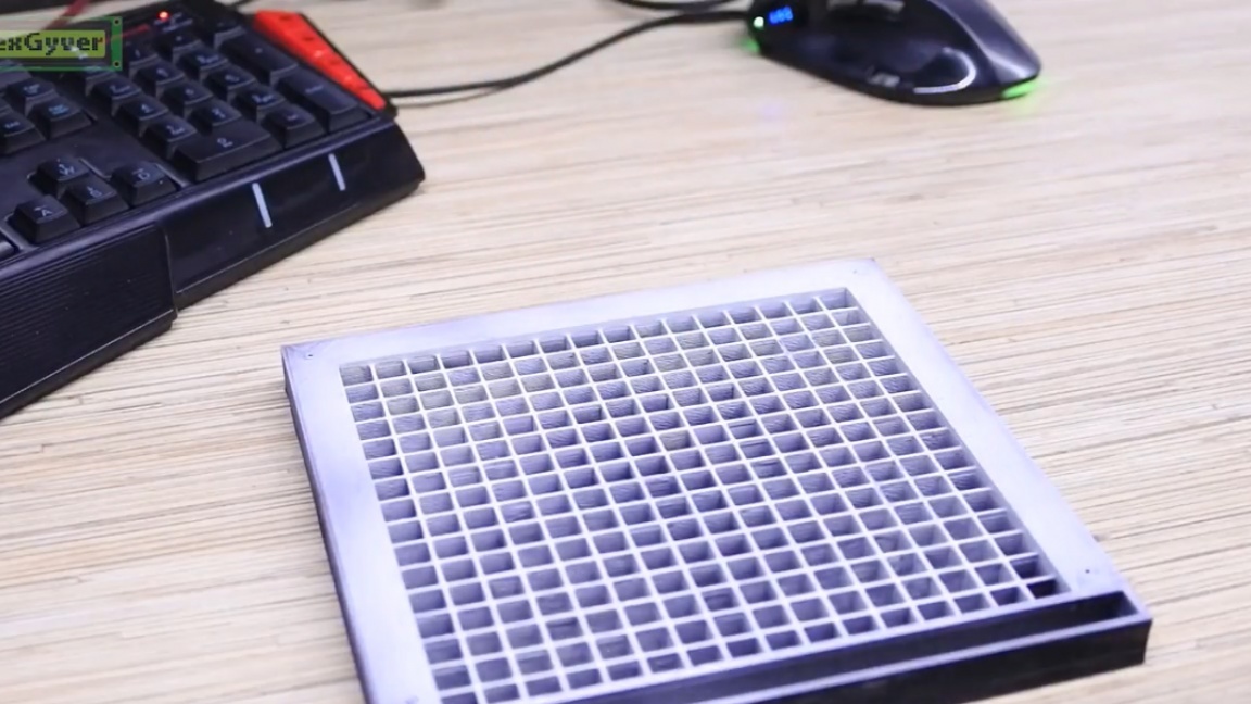
Actually, here is our matrix without a lattice, LEDs as they are.
We put the lattice, it becomes already better, this is because we are looking at an angle.
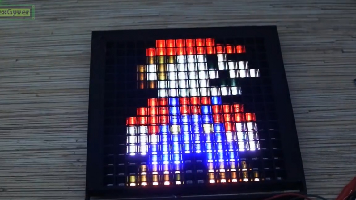
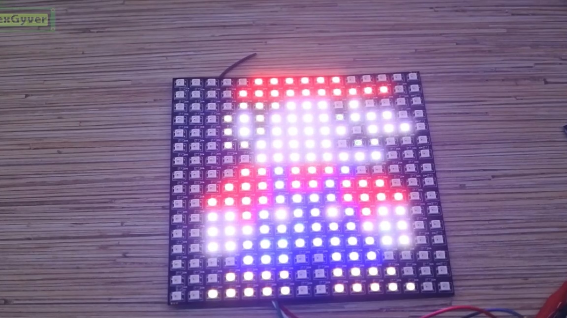
Now look what happens if you add a diffuser in the form of a sheet of paper.
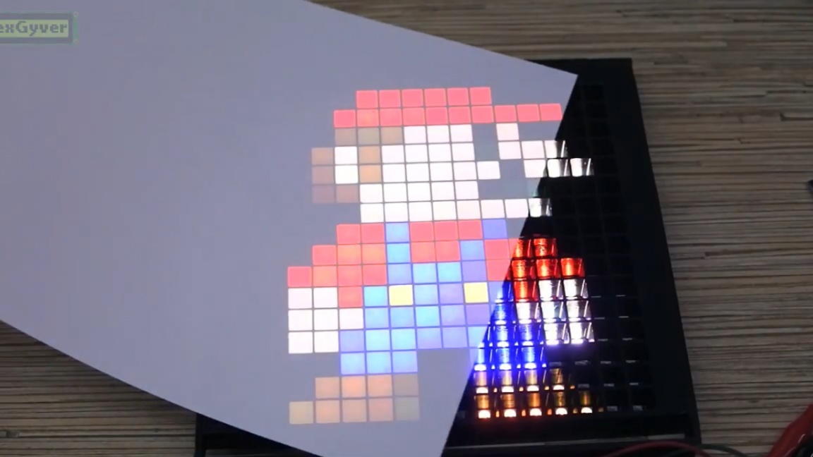
But the matrix, like any display, works in the rgb color space, and its background should be black for a more correct color perception. The author tried several options and settled on the film for auto tinted and frosted plastic. In tandem, it all works just fine.
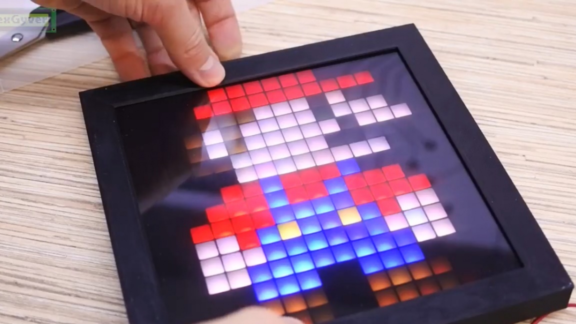
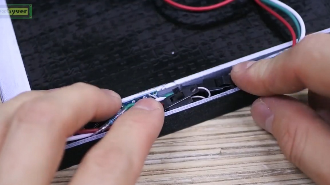
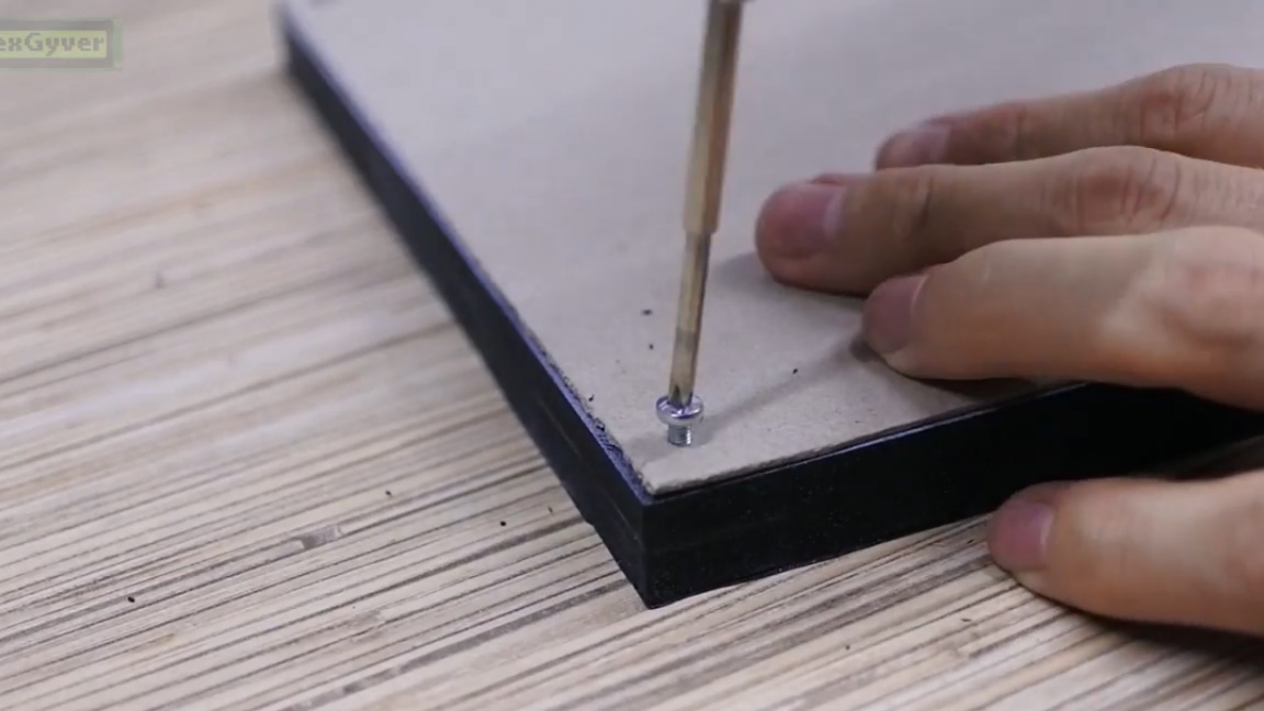
We collect all this. It remains for us to finally solder the whole circuit, place it inside the pocket, fix the matrix with the back from the photo frame (or rather find an aluminum sheet) and fix the outer frame.
We connect the power. The author used a laboratory power supply so that we can see the current consumption.
The first mode is drawing.
The next mode is transferring pictures. We select a picture as our file manager (in this case, Mario on a 16x16 black background).
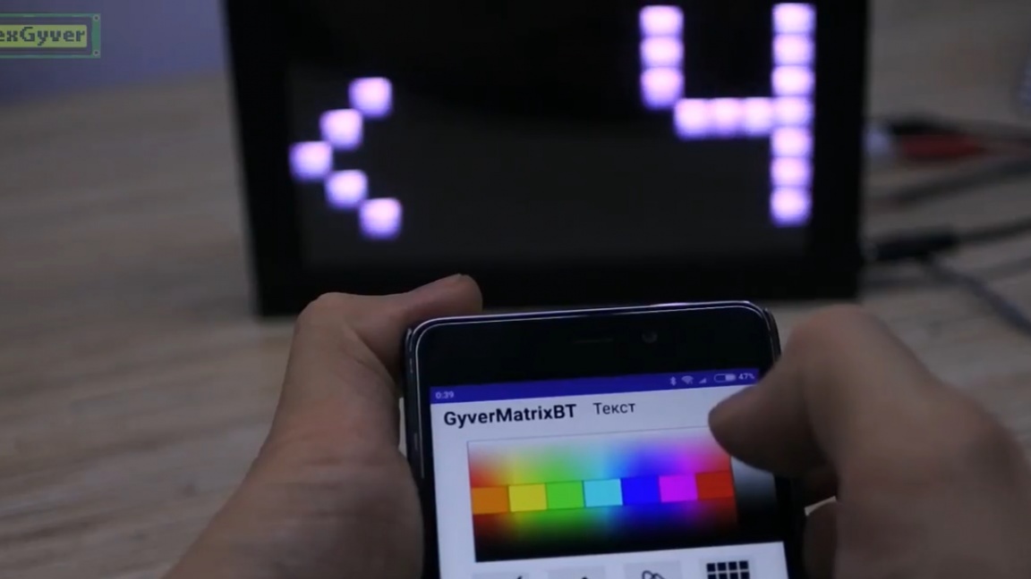
The next mode is a running line.
The next mode is effects. Some effects can be combined with running text and with pictures.
More effects in the author’s video:
Thank you for attention. See you soon!