
Dummy boards with 0.1 inch pitch pads have been made unchanged for many decades. Meanwhile, in the technique disassembled by masters into parts, output components are found less and less, and SMD - more often. Using them in a new design, you have to make a printed circuit board, since the breadboard is not suitable for this. Or can it be adapted somehow? The author of Instructables under the nickname osgeld says: as much as possible! Do not believe? Read on.
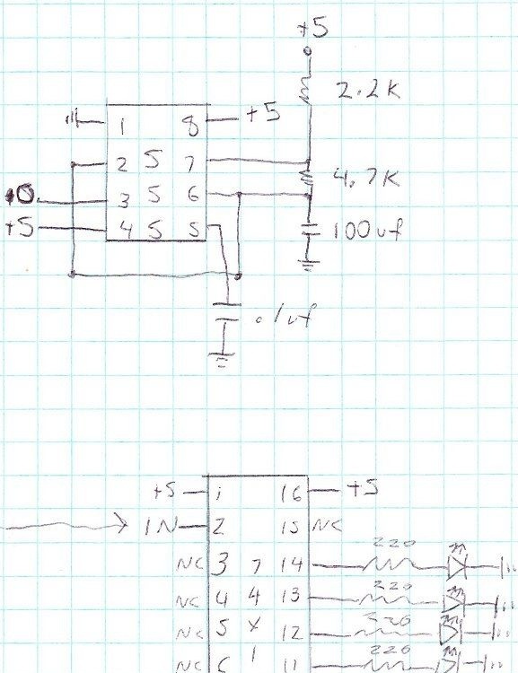
To prove this, he assembled on such a board a design consisting of SMD components almost completely. Exceptions are the 555 timer and ceramic capacitor in the clock. All together will be a device consisting of the aforementioned generator, a four-digit binary counter, the status of the outputs of which are indicated by LEDs. If you are familiar with the basics of the binary number system, you already know that each subsequent LED in this circuit flashes twice less than the previous one. Perhaps you even built a similar design on conventional components.
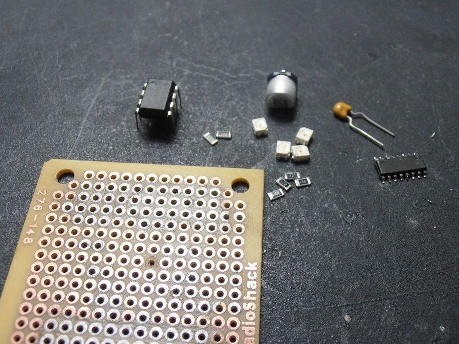
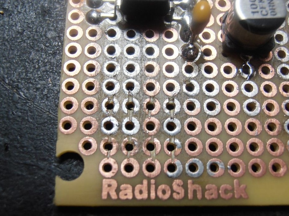
Everything is ready for assembly.
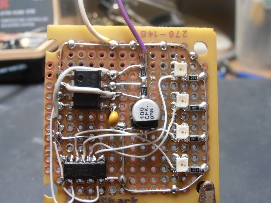
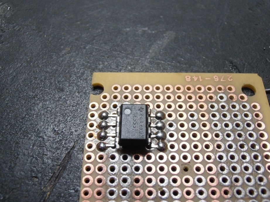
Let's start with the output components. Are you used to placing them on the breadboard from the side opposite to the conductors, passing the conclusions through the holes? And osgeld did not do that. It is very inconvenient when the output components are located on one side of the board, and SMD on the other. So you can confuse the direction of counting conclusions. Therefore, he decided to solder the output components from the side of the conductors, not passing the leads into the holes, but having molded them as shown in the photo.
This is also convenient because the assembly does not have to be constantly turned over during assembly, and there will be nothing on its back side (which used to be the front) ... nothing. Neither parts, nor even conductors, if the board is single-sided. It will also take up less space in thickness. Having covered one of the copper circles with flux, he then tinned it, applied the microcircuit with one lead, heated the solder, correctly oriented the microcircuit, then, fixing it, removed the soldering iron. Now that she is motionless, it’s easy to solder the rest of her conclusions without holding her.
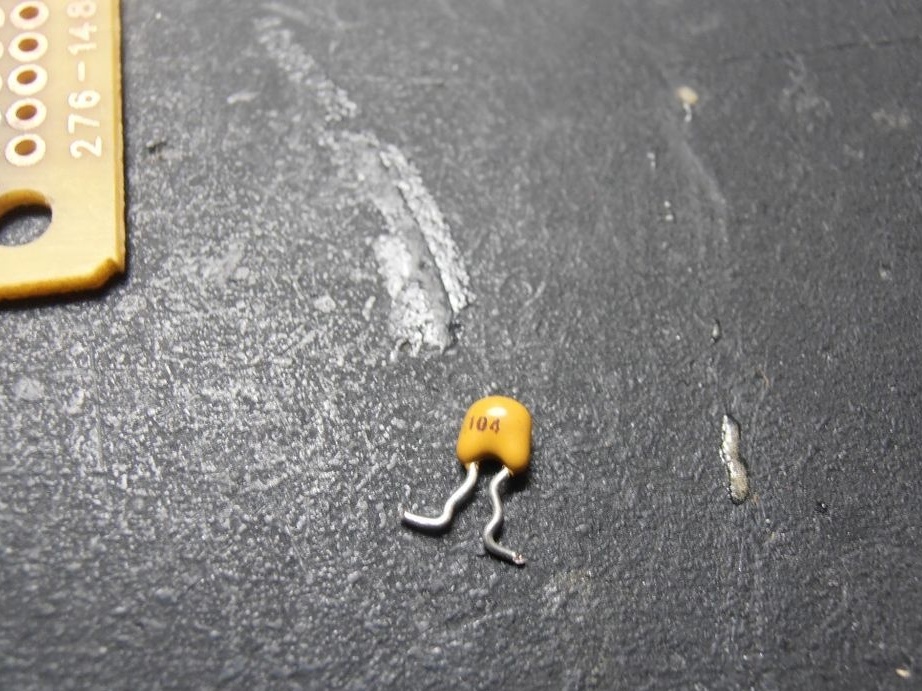
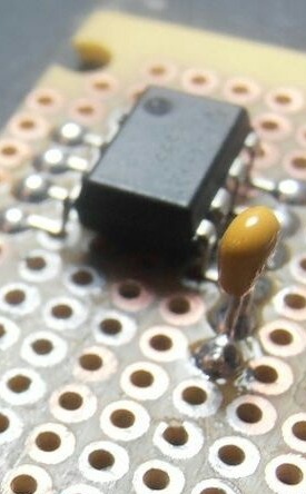
The ceramic capacitor is very easy to solder.
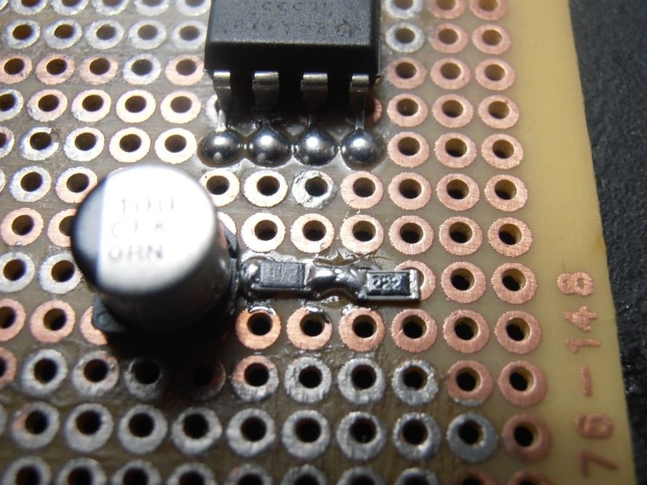
The next component is an electrolytic capacitor. He is already here in the SMD version. Attaching it to the board, osgeld discovered that there might be a third circle between its terminals, which after soldering will touch both terminals and short the part. He followed and oriented the capacitor in such a way as to exclude this situation. And then it disappeared.
He did this operation as follows. I got one contact pad and slightly “grabbed” one of the capacitor leads to it with solder. The opposite output was soldered to another site, then returned to the first and finally soldered it.
SMD resistors, ceramic capacitors, diodes are very convenient for soldering to a breadboard. Their osgeld simply places tweezers between two pads and solders. Components of size 603 are too short, but you can contrive and solder, 1206 are almost perfect, 805 is generally better not to think of! If the conclusions of the component are wide, they can take two or even three sites at once.
It shows an electrolytic capacitor and two resistors already soldered into the board. A jumper of solder is made between the resistors - a wire will be soldered to it.
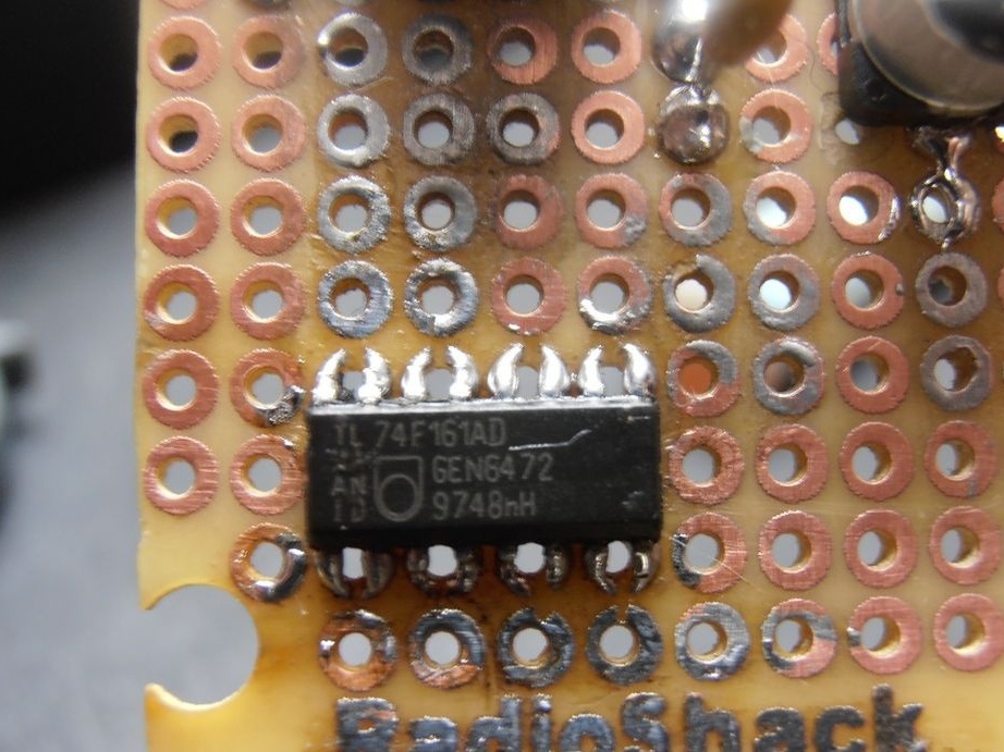
We proceed to the most interesting - a microcircuit with planar outputs (in this design, this is a counter 74F161). Here, their step is already - 0.05 inches, which is half the step of the contact pads on the board. What to do? To make or buy an adapter? Solder short wires to the chip? The solution invented by osgeld is simpler and more elegant. With an office clerical knife, he cut each of the sites on the board into two parts.
After that, I soldered a microcircuit to them. Beauty, as if it were originally! This method is not suitable for prototypes with metallization inside the holes, it will have to be drilled.
Then come the SMD LEDs. At osgeld, they ended up in four-pin buildings. Two outputs on the one hand, and two more duplicate (like clock buttons) on the other. They coincided with the contact circles on the board very precisely, and the master easily soldered them.
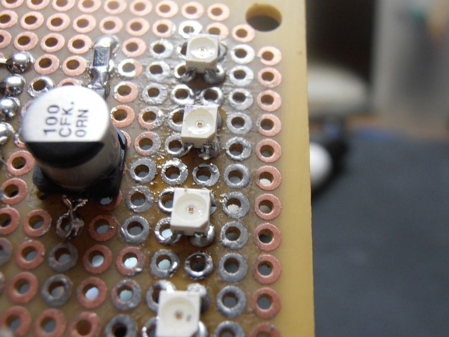
Adding resistors to limit the current through the LEDs, he connected the components with wires according to the scheme.

Yes, by the way, let's talk about wires. Single-core wires, according to osgeld, are good to take from a twisted pair. Stranded, with better insulation - from ATA cables, they are also IDE. Microcircuits with a very small lead pitch will have to be isolated from the pads, and then connect their leads to the leads of other components with a thin winding wire in varnish insulation.
Meanwhile, the wizard already shows how the finished circuit works.
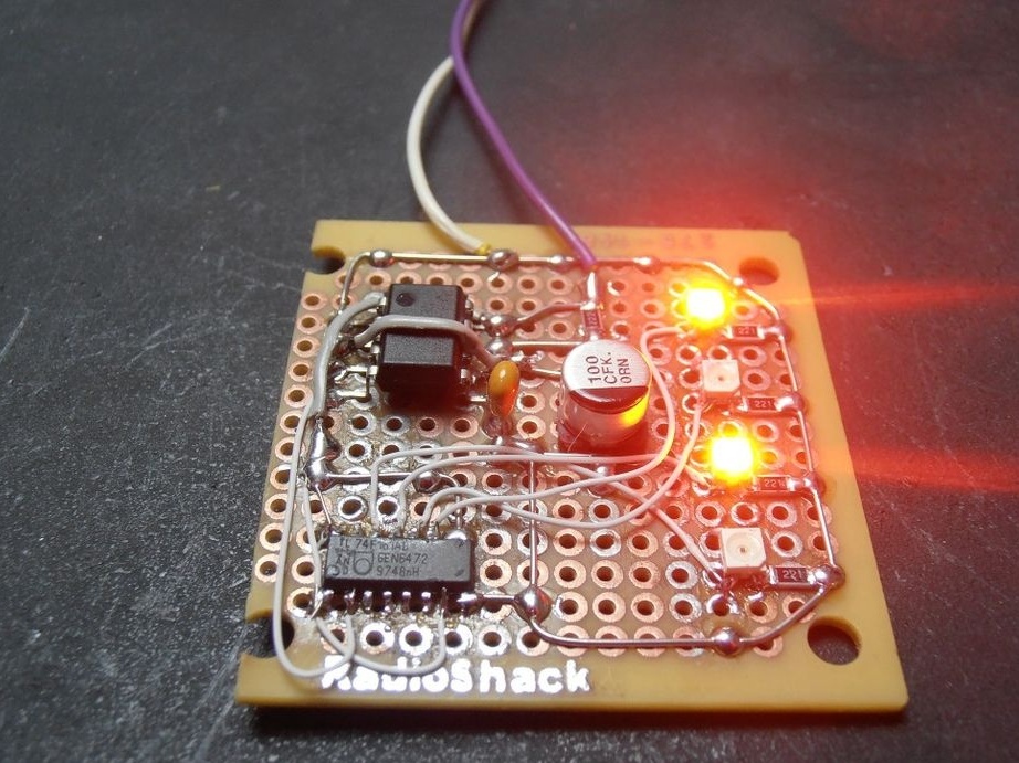
And if you follow these tips and do everything correctly and accurately, then yours homemade on breadboards with SMD components will work fine.
The only drawback of this tip is that it does not fit breadboards of another popular type - breadboard. In order to use SMD components on them as well, you will have to resort to soldering conclusions or using adapters, as before.