
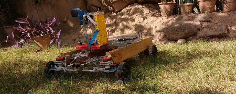
The author of Instructables under the nickname droiddexter made a rather complicated self-propelled model. it robotwhich can be controlled from a laptop. To control the movement of the platform, a keyboard is used, and the operator can give commands to the manipulator arm from a joystick connected to the same laptop. The joystick is used like Logitech Attack 3, but another similar one will do. Breadboard-type breadboards and jumpers with DuPont connectors (although other companies are now producing them) allow you to quickly reconfigure and modify the design of the robot, as well as its composition.
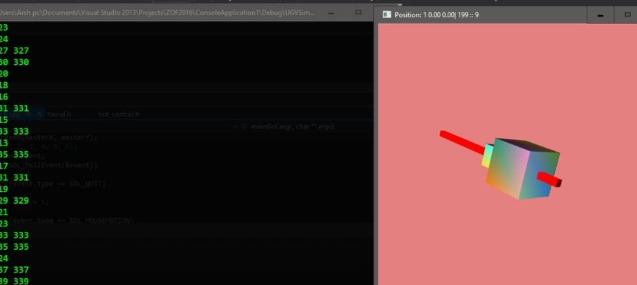
An application running on a laptop repeats on the screen in three-dimensional form the current position of the manipulator arm, and also displays information about all its movements in the text console. The program is written in C ++ and has a simple event architecture.
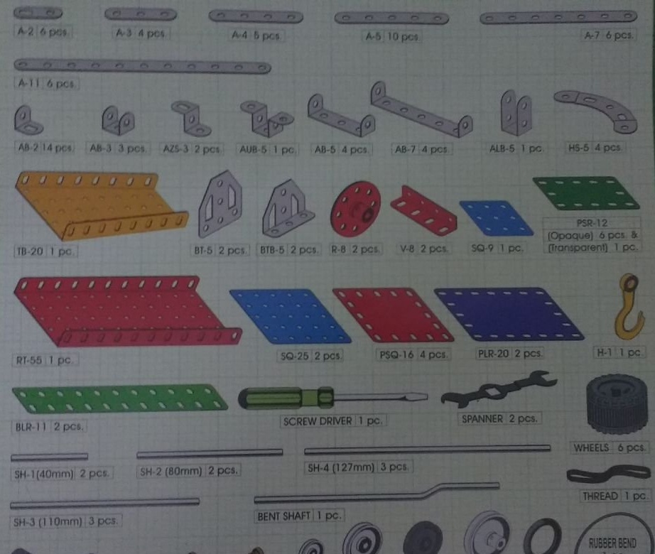
As droiddexter applied in homemade a lot of details from a metal constructor (Meccano or his clone), he attached an illustration with a list of these parts and their alphanumeric designations. In the photographs of the robot nodes, he brought along with the details from the designer the corresponding designations from this list.
The device uses two boards at once Arduino: one Uno (in the robot) and one Nano (connected to the laptop). Each of these boards is connected via a 2.4 GHz NRF24L01 module through standard adapters with built-in 3.3 volt stabilizers and blocking capacitors. There are generally five power sources: two 12-volt batteries, two 9-volt batteries, and one 8.8-volt lithium-polymer battery. In such a strange way, the droiddexter recalled BigTrak, known here as Electronics IM-11. True, there are only two power sources. Jumper type DuPont master took 120 - 40 pieces of each of the three types. Servos - two types: TowerPro MG995 - four pieces, TowerPro SG90 - one piece. Still needed: a five-volt stabilizer (any, even 7805, but better pulse) and two collector motors at 500 rpm with gears.
Following the droiddexter proceeds to the selection of mechanical components. He takes two wooden bars 540 mm long, 60 mm deep and 25 mm wide, fiberglass sheets (require protection of the hands and respiratory organs during processing), the above-mentioned metal constructor (it took two sets), four wheels with a diameter of 100 mm and a thickness of 20 mm, calculated on a 6 mm shaft,two holders with bearings and shafts for those wheels that rotate freely rather than driven by electric motors, six servo holders and two motor holders with gears for the remaining two wheels.
The design of the robot droiddexter divided into large modules. Any of them can be removed, and then reconfigured, repaired (which is very convenient - you do not need to put the entire model on the table) or replace it with another one that performs a different function.
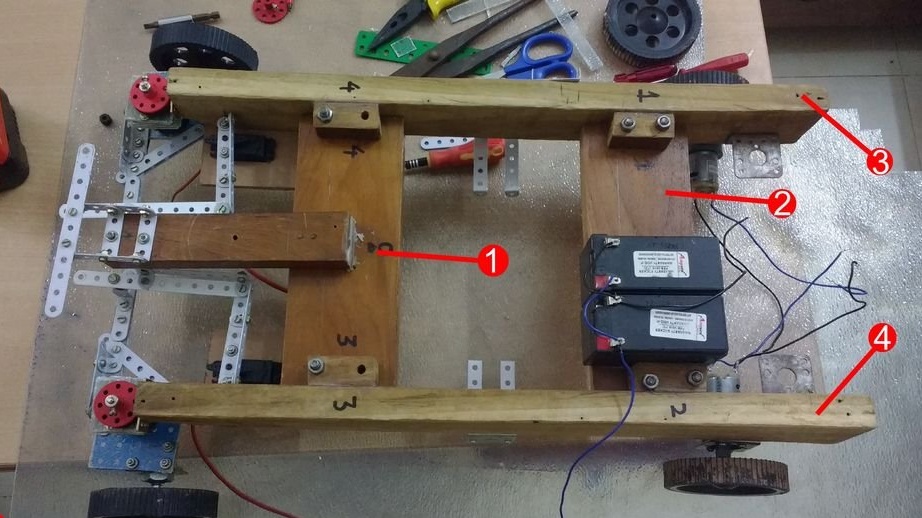
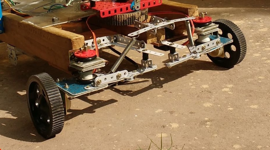
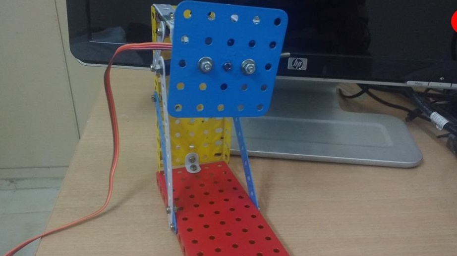
At the moment, there are four modules in the robot, they are shown in Figure A. The third and fourth modules support the front and rear wheels, as well as the steering gear assembly. The first and second modules connect the third and fourth to each other, the second module also carries two 12-volt batteries that feed the wheel drive motors and servomotors. The batteries are glued with wood glue.
Another function of the first module is to additionally support the steering gear assembly. Otherwise, under the influence of fairly strong loads, it is deformed. Therefore, the first module includes a forward protruding wooden block, while the second is connected to the steering gear loosely - two springs and a hinge.
To increase the strength, the droiddexter rationally applied parts made of fiberglass and steel in the steering mechanism.
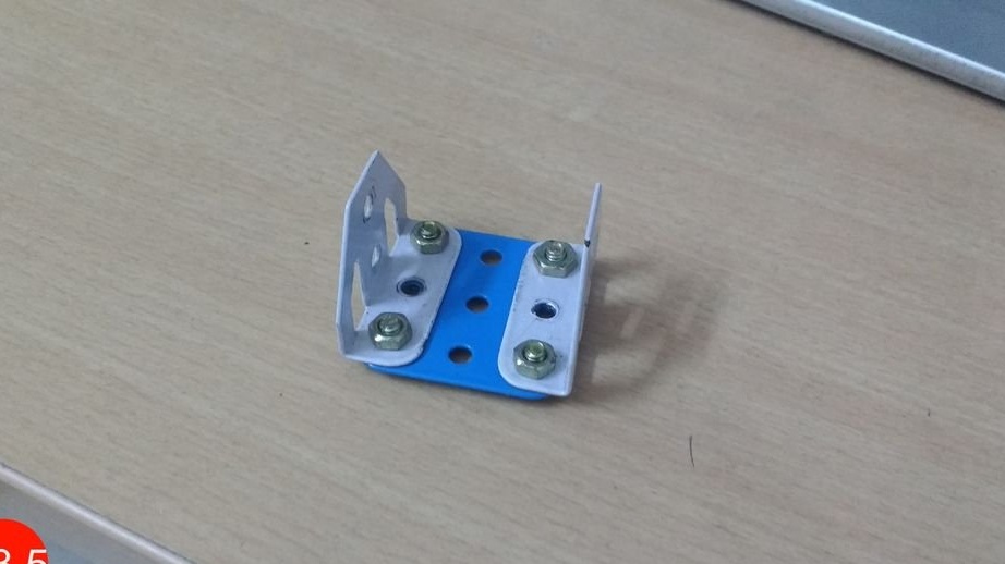
Figure A1 shows a large top view of module 4. Node A1: 1 carries the electronic part of the robot. A prototype board and Arduino are fixed on a piece of fiberglass, the rest of the electronics droiddexter attached directly to A1: 1. To do this, he took the L-shaped clamp and two parts AB-7, fixed on it with bolts and nuts.
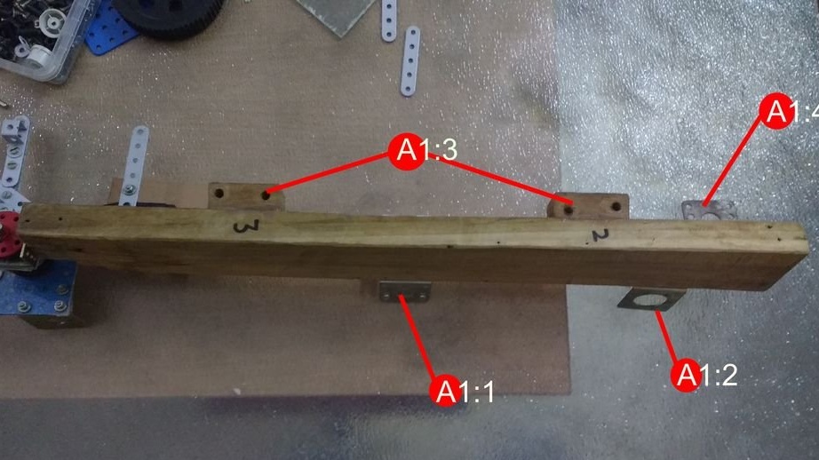
Node A1: 2 holds rear-wheel drive.
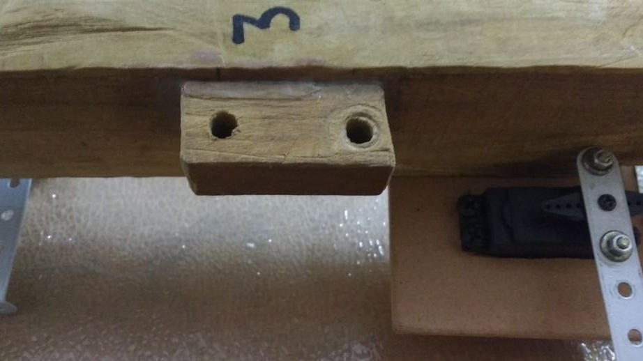
The A1: 3 node consists of two wooden blocks that the droiddexter glued to the frame with wood glue so that modules 1 and 2 carry all parts of the robot.
Node A1: 4 carries additional electronics to control the robot's movement motors.
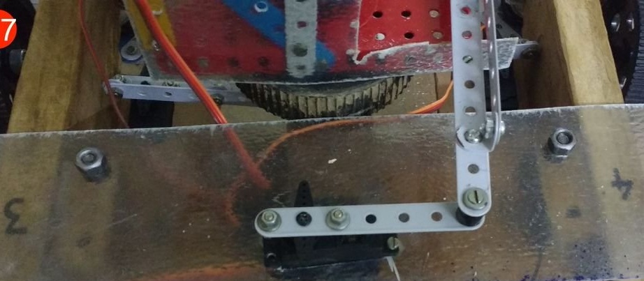
Now let's look at module 4 from below - fig. A2. Node A2: 1 is the main steering servo. Two of the three servos of the robot are responsible for taxiing. They were placed by the droiddexter on a sheet of hard cardboard and attached from the bottom to the front of the modules 3 and 4, nailed to the frame.
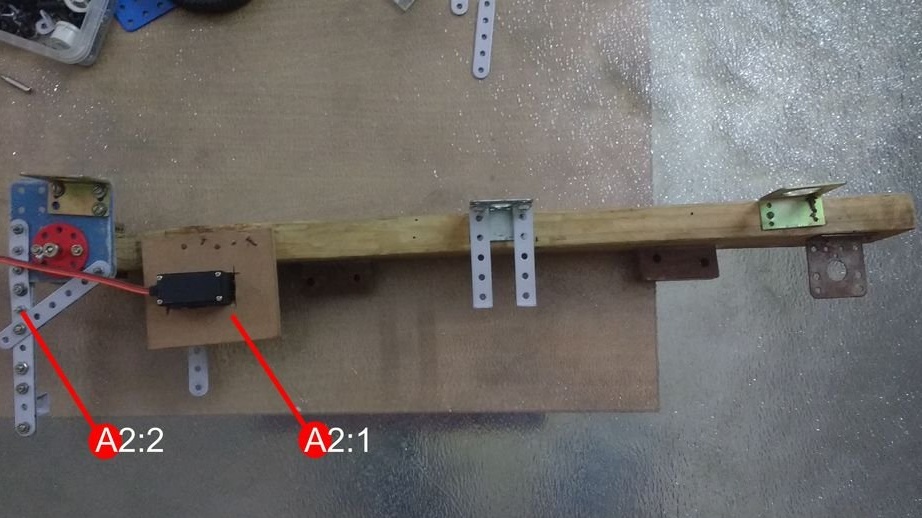
Node A2: 2 is one of the parts of the steering mechanism that the droiddexter connected to the servos, as well as to module 4. Also, the front wheels of the robot are located on it.
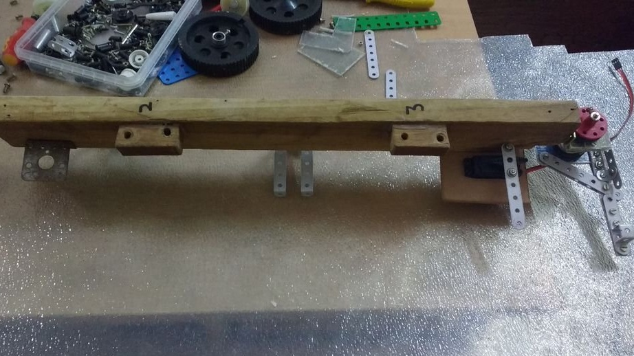
Figures A3 through A6 show, respectively, the node A1: 3, module 4, node A1: 1, and node A2: 2, the steering gear, respectively.
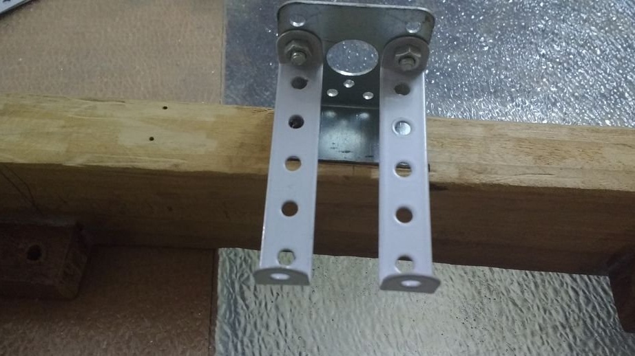
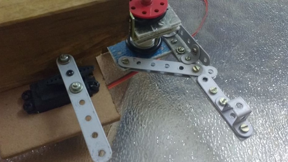
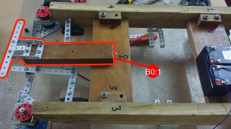
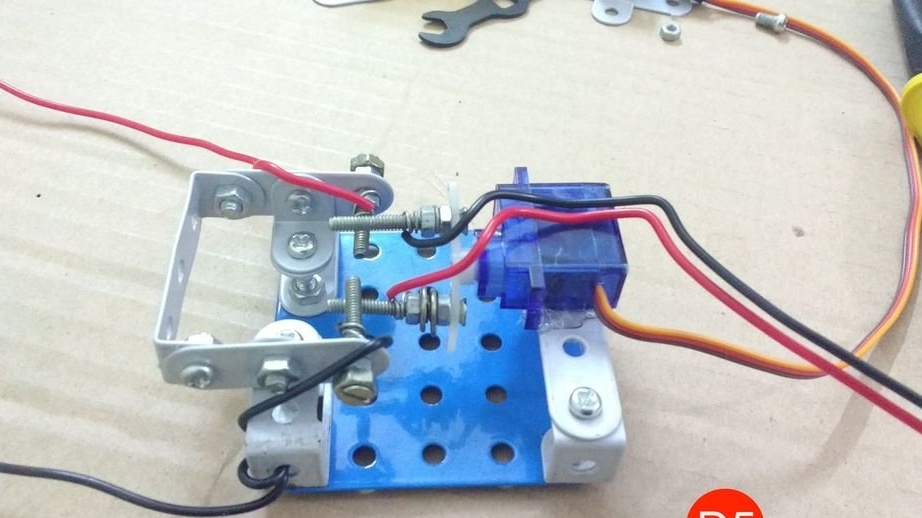
This mechanism, in turn, consists of three main components: the mechanical part itself, which changes the position of the front wheels, the servos themselves, as well as the springs that support all this in a vertical position under the action of servos. Figure B0 shows this spring system. Initially, droiddexter built a steering gear without a fiberglass carrier. It turned out to be fragile. When driving at fast speed, the mechanism broke down, and the metal bent. With fiberglass, the strength has increased, and the springs give the design flexibility, taking on the forces that could otherwise destroy it. Taxiing becomes smoother, and in a collision there is no transfer of destructive force to the servos. By adding spring holders to the B0: 1 assembly, droiddexter decided that the hinges could be fixed in the same way.
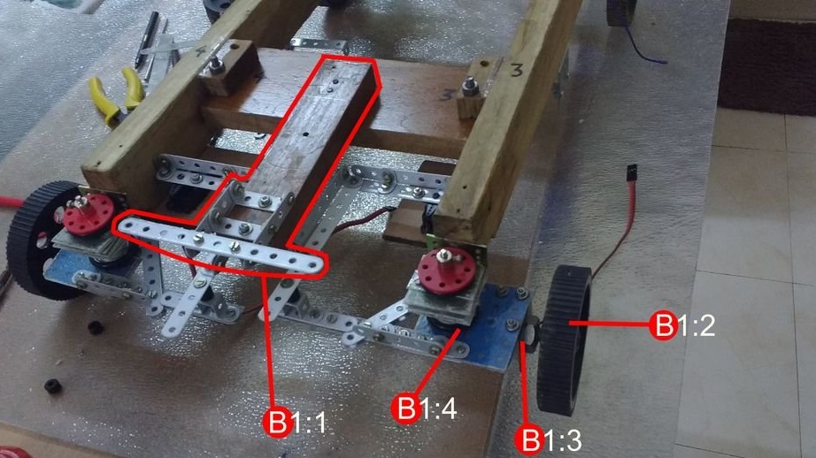
In fig. B1 is shown the same, but from a different angle. Additional fiberglass mounts were added after the first tests leading to breakdowns. To the details of A-11, A-7, A-5, droiddexter added similarities to stiffeners. Node B1: 3 is a wheel holder with an axle and bearing connected to an L-shaped clamp; these wheels are taxiing. B1: 2 - one of the wheels, they are very durable and provide sufficient clearance.
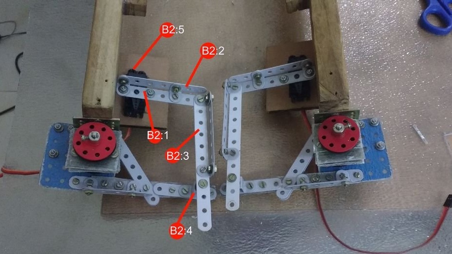
Node B2: 1 is part A-5 connected to the servo drive with two bolts and nuts. Washers are required. B2: 2 and B2: 3 - metal strips reinforced with stiffening ribs. B2: 4 - hinge to which washers and parts TW-1 are added for reliability.
From the following figures B3 to B14:
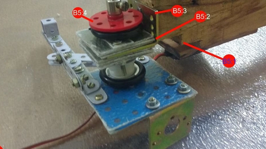
B5: 1 - a slot made so that when cornering at large angles, the steering mechanism does not rest against a block. As B5: 3, only high-quality L-clamps can be used. In them, the droiddexter made two holes for attaching to a tree.He set the clamps exactly parallel to the rest of the details. B5: 2 is a stack of fiberglass squares on each side of the L-shaped clamp.
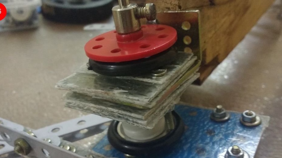
The order of the components is as follows. If you count from above: R-8, a small spring, PY-2 with a T-1 attached to it, three layers of fiberglass, an L-shaped clamp, three more layers, another PY-2, a plastic holder, another PY-2 with T- 1, then the steering gear, then R-8.
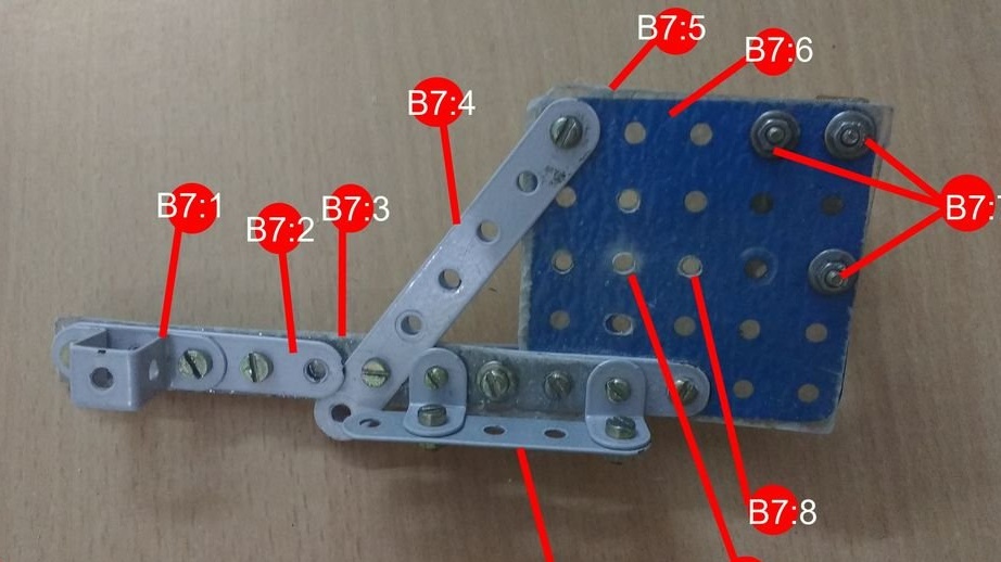
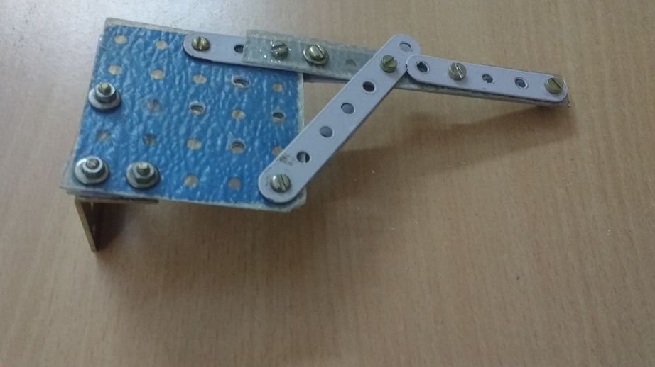
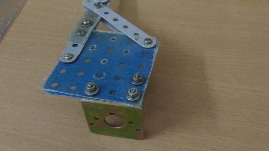
In assembly B7: 1, part AUB-5 prevents loosening of the screw connection. Knots B7: 2 to B7: 6 are multilayer fiberglass stacks already familiar to us. At node B7: 7, the droiddexter applied short bolts so that they would not hit the rotating parts. B7: 8, B7: 9 - holes in fiberglass for parts SH-2 (80 mm) and R-8. Node B7: 10 prevents the metal strip from bending, as parts SQ-25 and A-11 together form a hinge.
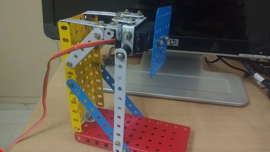
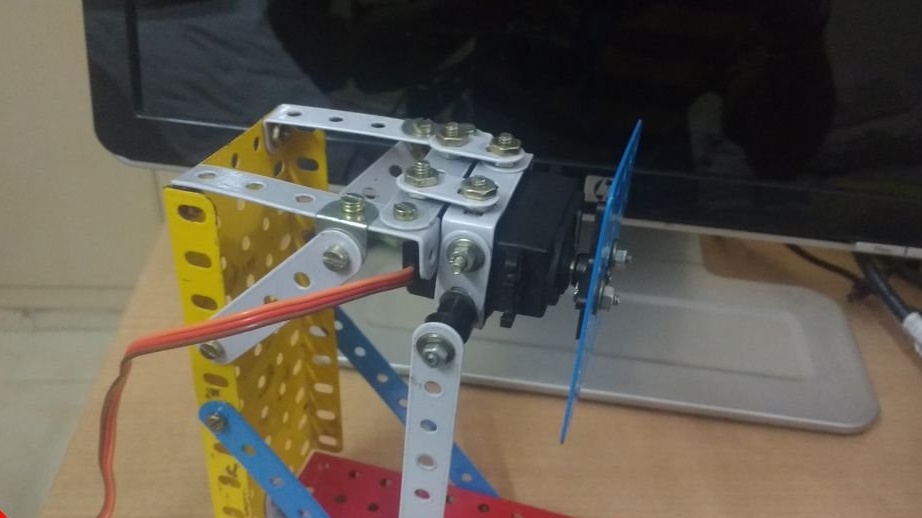
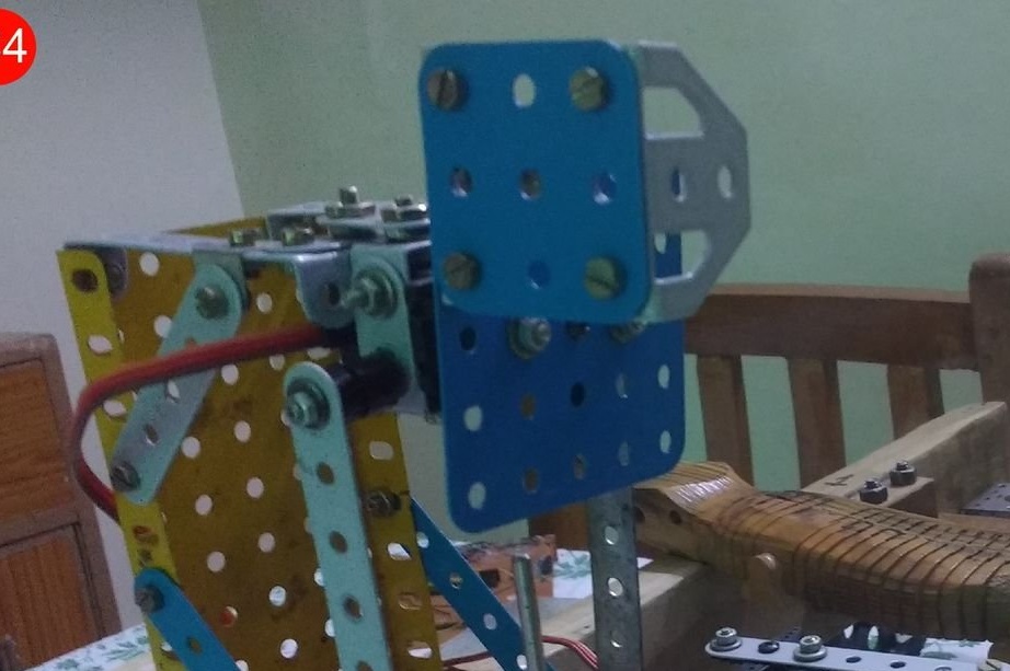
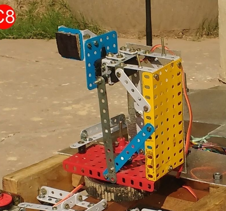
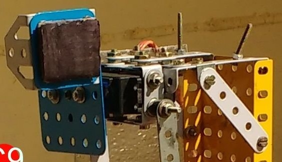
The articulated arm can move the end link up, down, left and right, even if the platform is stationary. To move along the Y axis, the SH-4 part, 127 mm long, was passed through a wooden block. To move along the X axis, part SQ-25 is attached directly to the servo drive (Fig. C0 to C9).
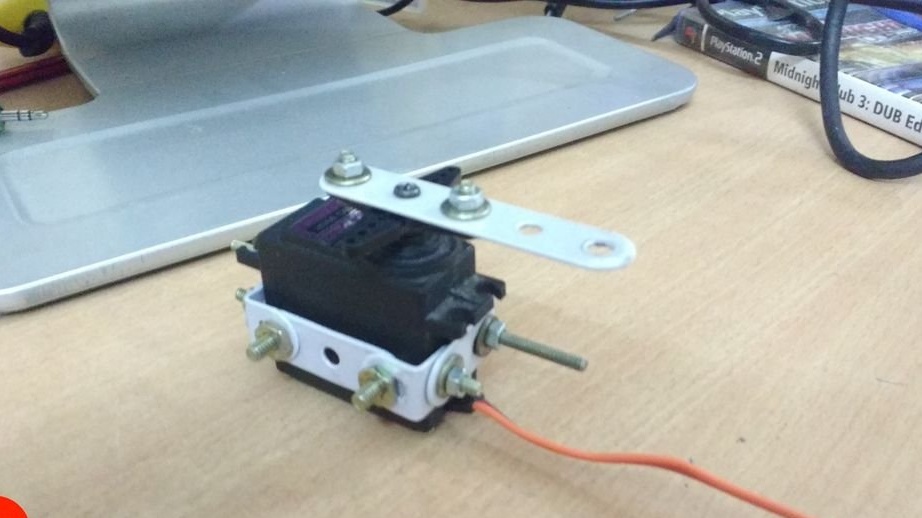
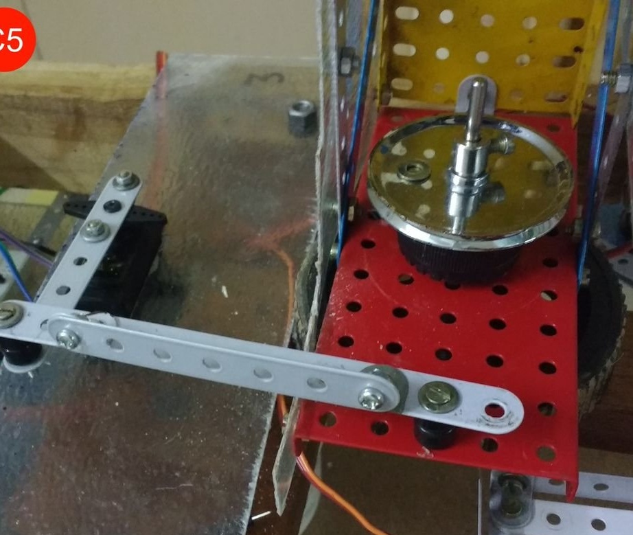
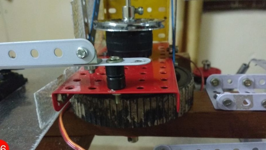
To control the engine speed, the droiddexter used a composite transistor TIP122, the PWM signal to which comes from Arduino. To change the direction of rotation of the engine, the droiddexter made an original mechanical polarity-reverser from a small servo drive. Before that, he had tried the H-bridge, but it turned out to be too weak. What prevented the use of a simple relay is not clear. Engines are powered by two 12-volt batteries connected in parallel.
From the photo it is very clear how the polarity reverser is arranged and works, but the translator would connect the movable contacts not with direct, but with spiral wires.
For quick reconfiguration, all connections are made on a breadboard type breadboard. The droiddexter antenna is located on the side and high enough. The robot movement motors, as indicated above, are powered by two 12-volt batteries, since lithium-polymer batteries suitable for the parameters turned out to be too expensive for the master. The servomotor of the polarity reversal device is powered by them, but through a five-volt stabilizer. Eight-volt lithium-polymer batteries of a smaller capacity turned out to be more accessible for the master, he fed all the servos from them - both those that are used for taxiing and those that are installed in the manipulator. These drives begin to fail if the load capacity of the power source is too small, or many other loads are connected to it.
Arduino is powered by a separate 9-volt battery through a stabilizer installed on the board nominally.
Of course, the “zoo” of power sources, some of which need to be changed, others to charge, is inconvenient, but it will do for the prototype.
The 2.4 GHz module, as described above, is powered by Arduino via a specially designed adapter with stabilizer. So it works more stable than when powered by the Arduino stabilizer itself.
Arduino conclusions are used as follows: 6 and 7 - control of servo-drives of the steering mechanism, 2 and 3 - of the manipulator, 5 - device of polarity reversal, 8 - PWM for collector displacement motors, 2, as well as from 9 to 13 - information exchange with 2.4-GHz module.
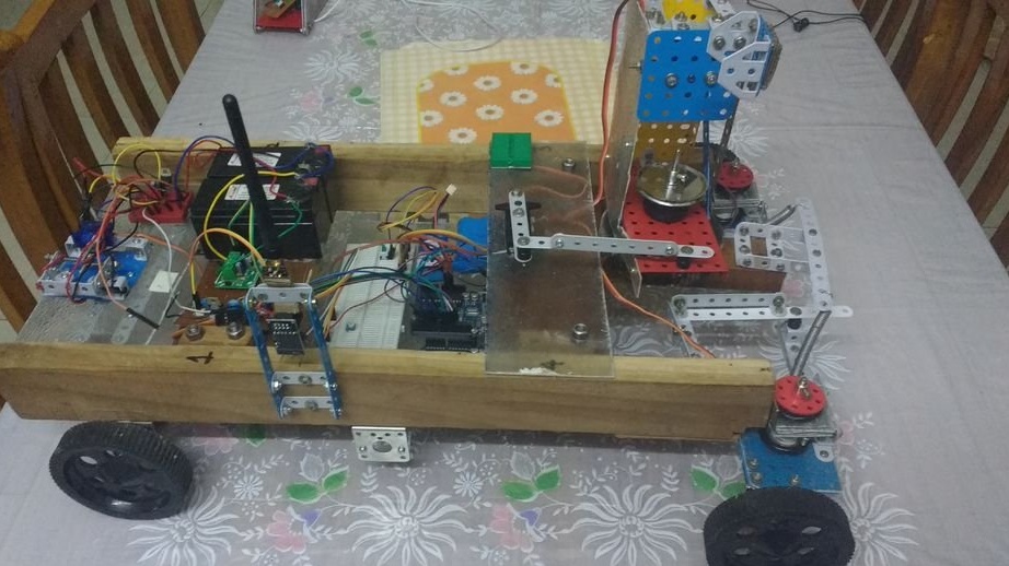
All together looks like this:
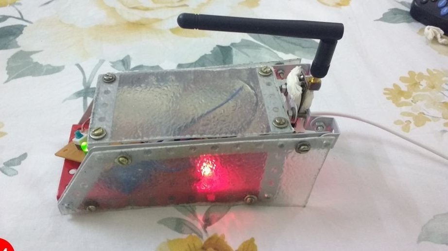
From the side of the laptop, everything is quite simple: Arduino Nano, the same adapter with a stabilizer and the same 2.4 GHz module. Powered by a 9-volt battery. The body is made of fiberglass and metal parts.
The software is not ready yet, the author will share it when both the software and hardware parts leave the prototype stage. It is written in C ++ using SDL, and it provides a three-dimensional display of the current position of the manipulator, moving the platform by commands from the arrow keys, and the manipulator by commands from the joystick, and changing the speed by commands from the wheel on the joystick. So that the reaction to the commands from the joystick is not too harsh, software smoothing is implemented. The joystick transmits data on the position of the axes in the range 0 - 32767, they are programmatically converted to the range 0 - 180 - in this format they accept servo commands. Information is transmitted in packets, each of which consists of five integers with data on the required positions of all actuators.
By controlling the robot, the user can simultaneously admire such a beautiful thing:
After exiting the prototype stage, everything will be transferred from the breadboard to the printed circuit board. Composite transistors heat up quite a lot, they require a printed circuit board and good heat sinks in the first place.
The fact that when processing fiberglass is necessary to protect the hands and respiratory organs, droiddexter was convinced on its own experience and will no longer work with this material without personal protective equipment ever!
Hammering nails is better with a large number of weak strokes than vice versa. Choose the power of the drill depending on the diameter of the hole and the material - yes, you will need two or three drills, but more nerves will be saved. To prevent the hole from moving, first press the drill strongly against the drilling point, and only then turn on the drill and gradually increase the speed. Wear gloves when working with any tools. When applying force to the screwdriver, make sure that her sting does not slip onto the other hand. Do not cut anything with a knife towards you, only away from you. Do not short-circuit power supplies.
And then you will use any of your homemade products without bandages, adhesives and plaster!