
Good day to all dear friends! In today's article, I would like to show you a rather interesting idea homemade. In this article we will consider how the easiest way to make a boron machine, which in turn can be used for various purposes, it will perfectly cope with drilling, sawing, and grinding. In general, in general, such a thing is necessary for every master in every house and the garage, and many have such a thing. If you don’t have such a thing, then I definitely recommend purchasing it, but if your need for this thing is small and you occasionally need it, and therefore you didn’t want to fork out for a factory-made copy, then this homemade product is perfect for you. In this homemade product, the same engine will be used that is used in the factory copies, and therefore the power of the homemade product will not be inferior to the factory tools, and may even exceed. In general, the homemade product is very interesting, so let's not pull with a long introduction, let's go!
For this homemade product we need:
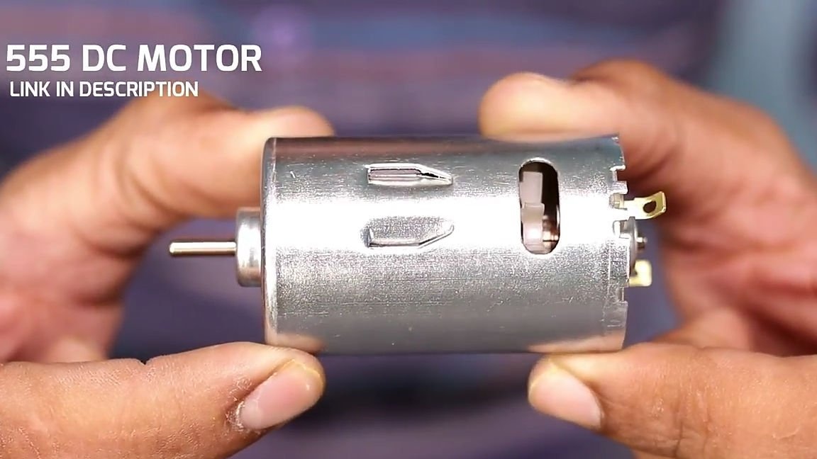
- Class 555 collector motor
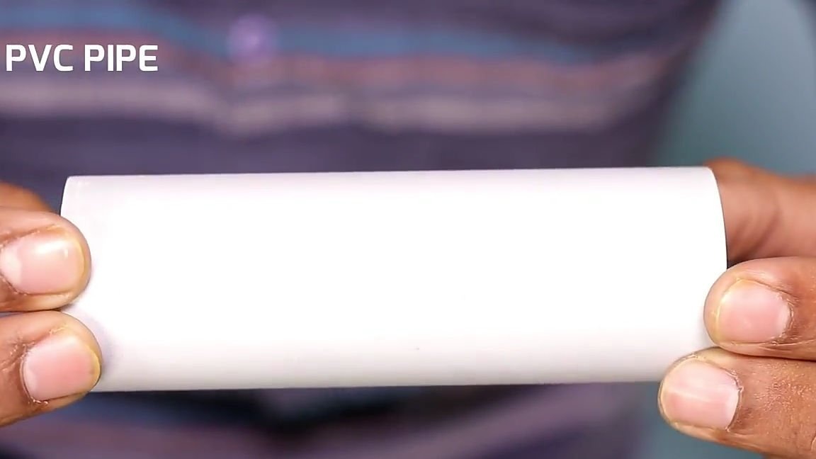
- PVC pipe
- ORG. Glass
- Self-tapping screws
- wires
- Switch - switch
- Power connector
- Power supply 12-24v
- Drill chuck
- Motor mount from a radio-controlled model 1/10; 1/8 scale (optional).
Of the tools we will also need:
- soldering iron
- solder
- Knife
- Coarse sandpaper
- marker
- Hacksaw
- screwdriver
- File
- Tweezers (for comfortable soldering)
- Hammer
- Super glue
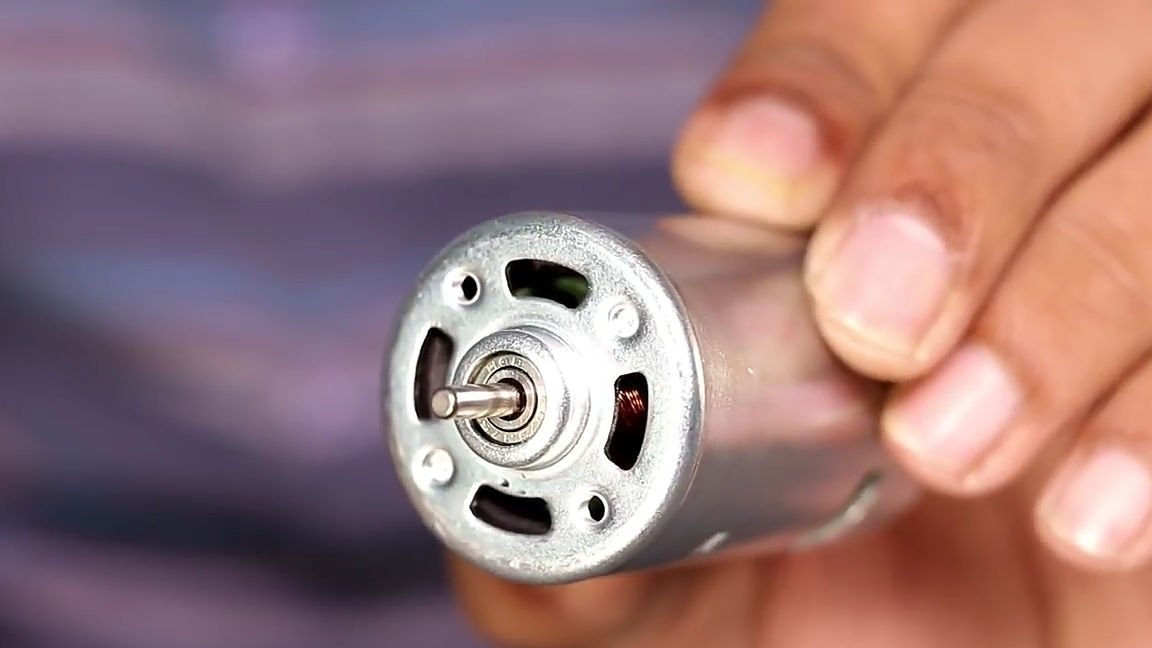
To begin with, we should decide on the choice of the most important and main part of our homemade product, namely with an electric motor. For this homemade product, a 555 class collector motor (this is installed on powerful radio-controlled models, drills, screwdrivers) with a large number of turns is perfect. The more turns the electric motor has, the more power, torque, but less revolutions per volt and vice versa. I personally recommend using some kind of good commutator motor, the shaft of which should sit on bearings, with a large number of turns, such an engine will give a large indicator of power.Using such an engine, you can work not only with wood, but also with metals, and you can compensate for a small number of revolutions with high voltage (no more than 24V).
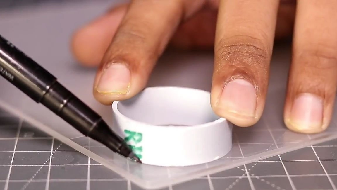
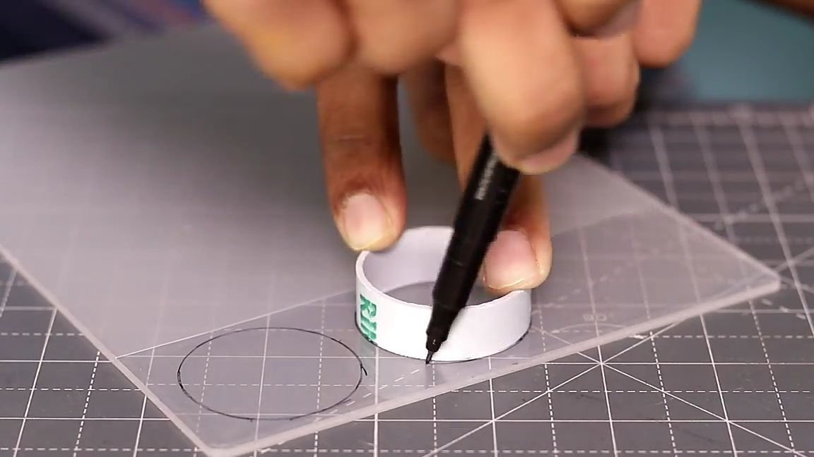
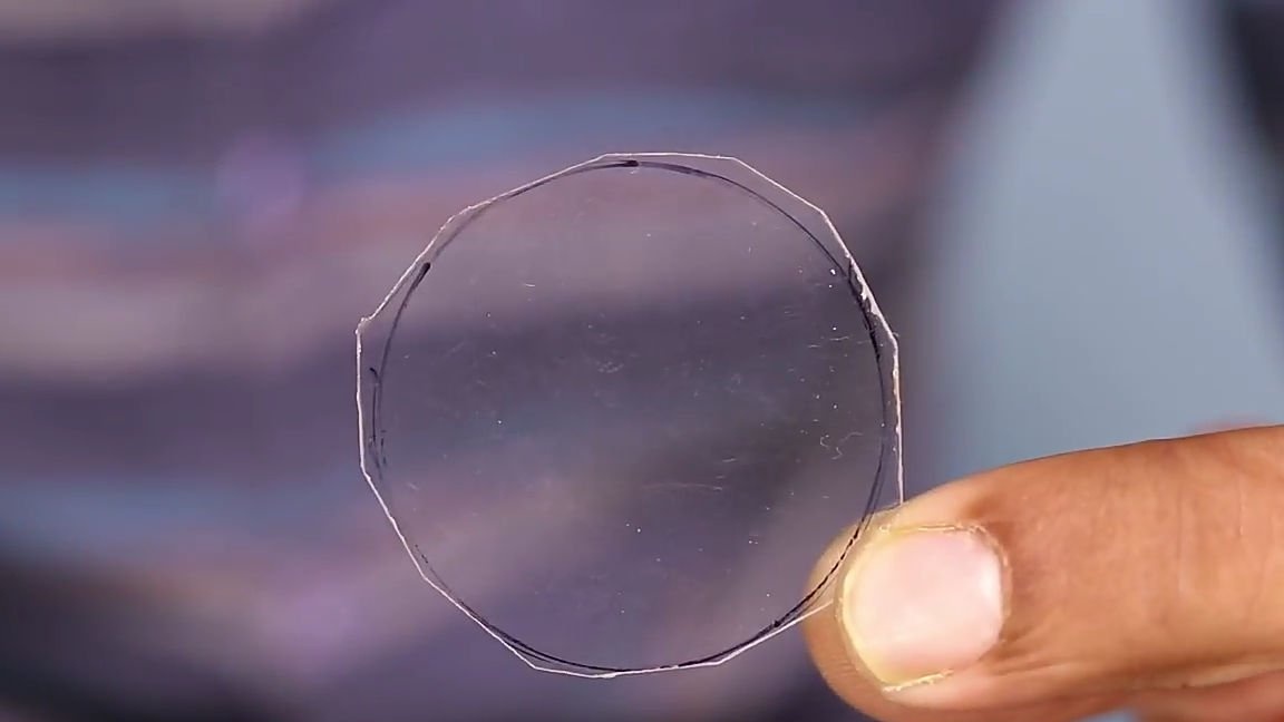
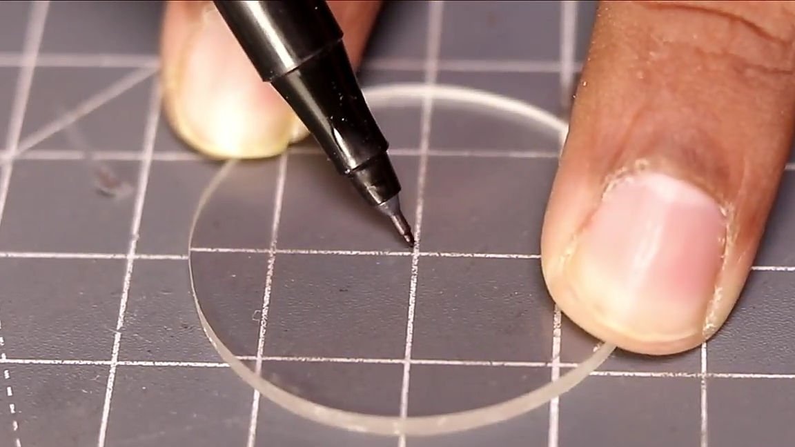
Having decided on the choice of the electric motor, we proceed to the assembly. We should take a PVC pipe no longer than 20 cm, and its inner diameter should either coincide with the outer diameter of the electric motor or slightly exceed it. The pipe you just picked up should be attached to a piece of ORG. glass and circle with a marker, in order to transfer the size of the pipe to the glass and cut it, we need to cut two identical circles, therefore, circle twice.
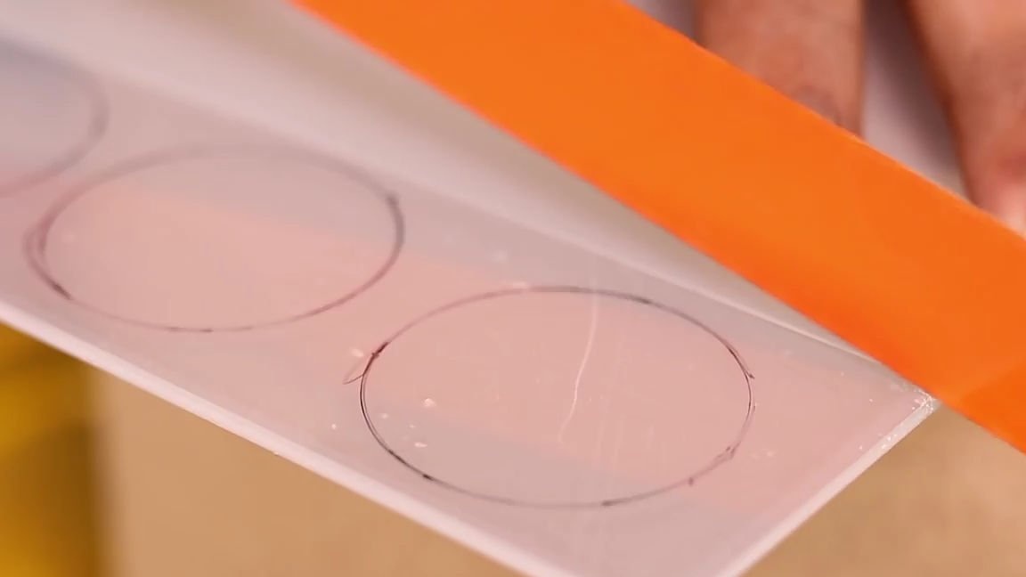
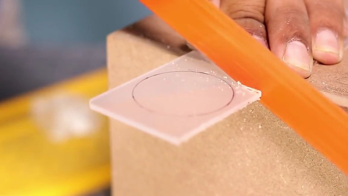
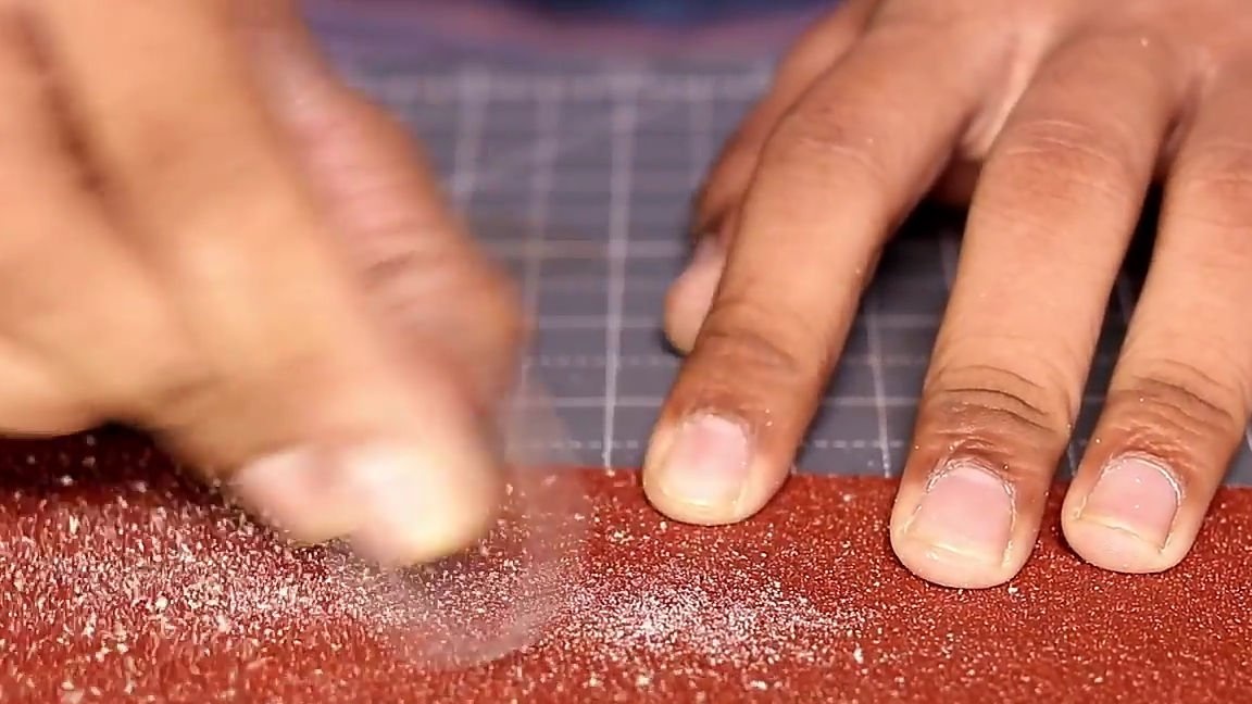
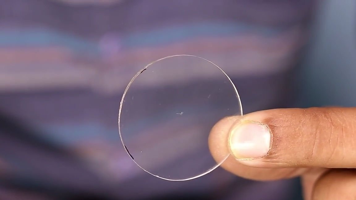
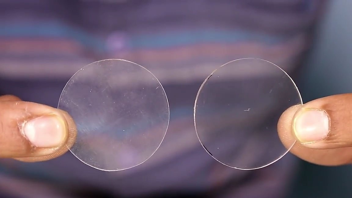
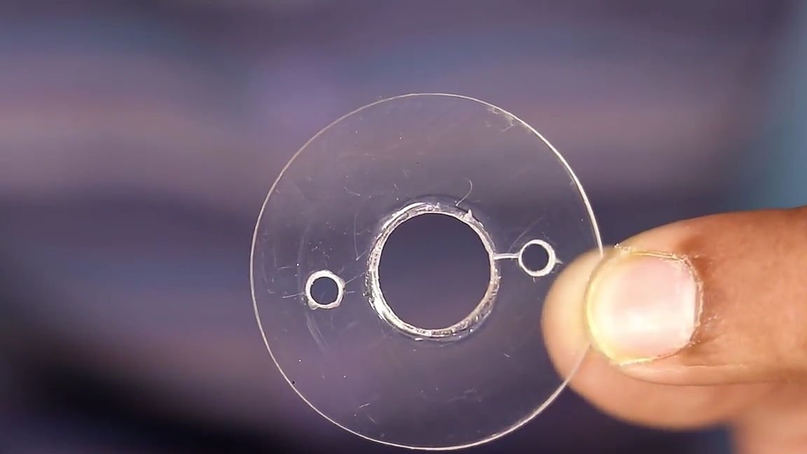
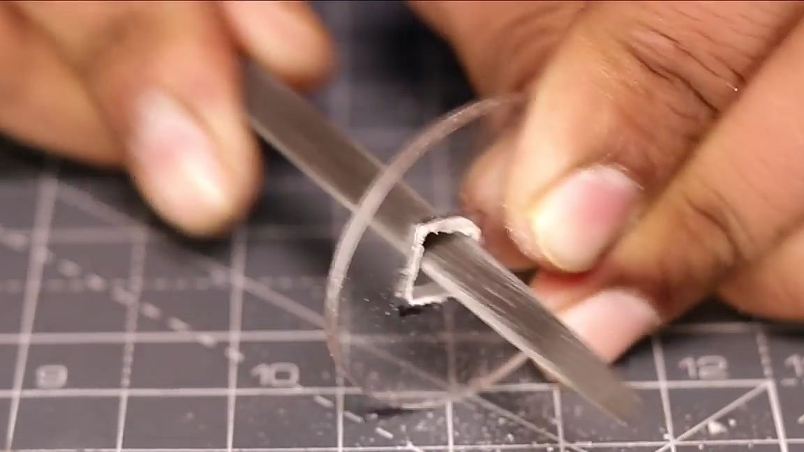
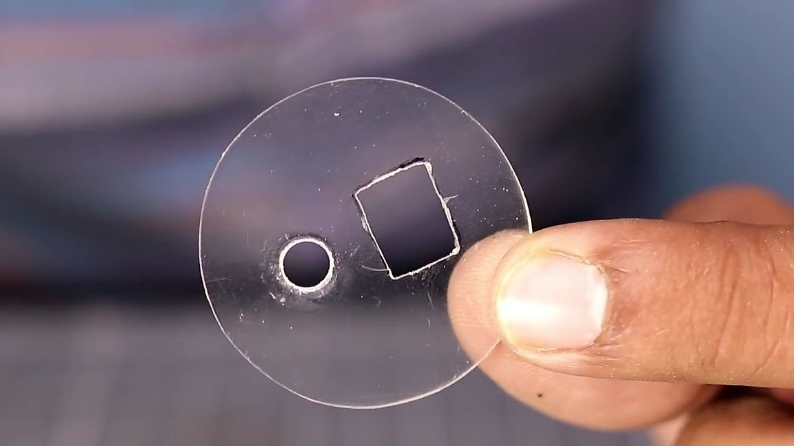
Then cut out the circles. In order to cut circles, you can use an ordinary hacksaw for metal, first cutting a square, and then give a shape similar to a circle by cutting corners. And then with the help of large grained, rough sandpaper and a file, we give the blanks the final look. As a result, after all the actions we should get two absolutely identical circles (see photo).
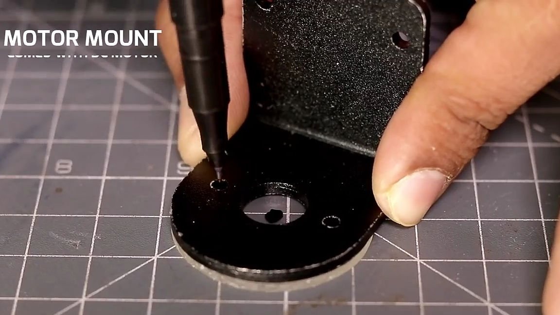
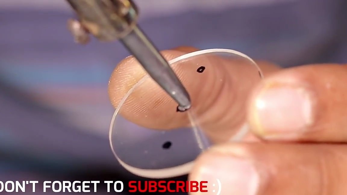
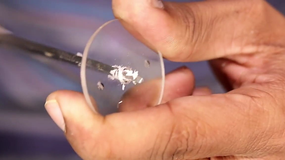
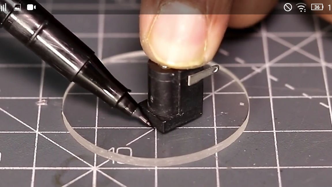
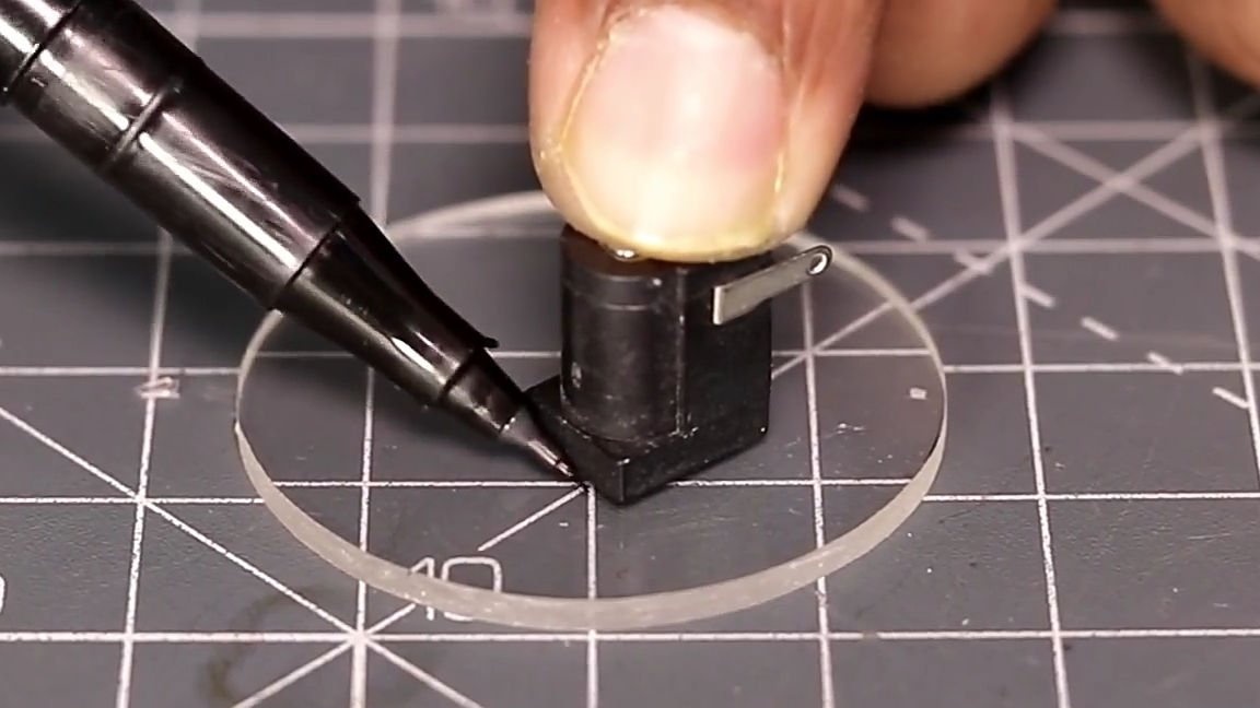
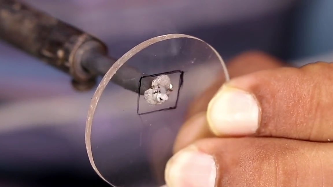
The next step is to take one of the previously made circles and mark its center with a marker. Then we apply the engine mount to the circle, so that the marked center is located in the center of the main hole of the engine mount. Attaching a motor mount, as mentioned earlier, mark the landing holes on the sides of the central hole with a marker. Then we make through the hot soldering irons through holes, and expand the central hole with a knife (or as an author, with scissors), so that the engine fits tightly and there is minimal backlash. That is, it should turn out the same way as in the photo below.
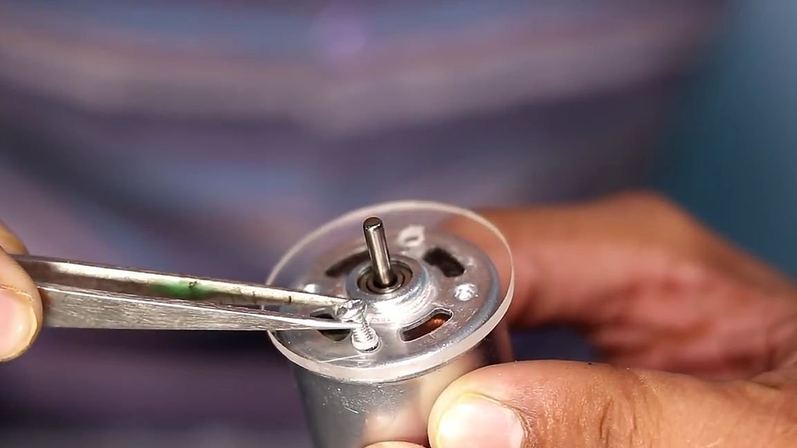
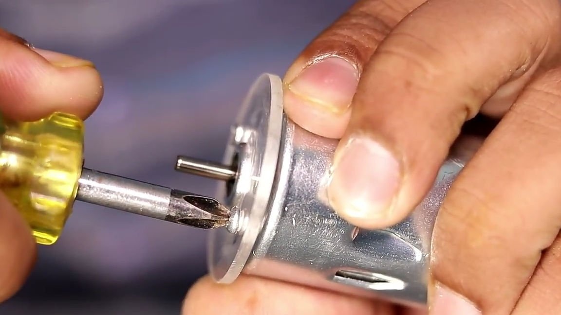
We connect the newly made workpiece with an electric motor, applying it to its seat, and fixing it with screws or self-tapping screws.

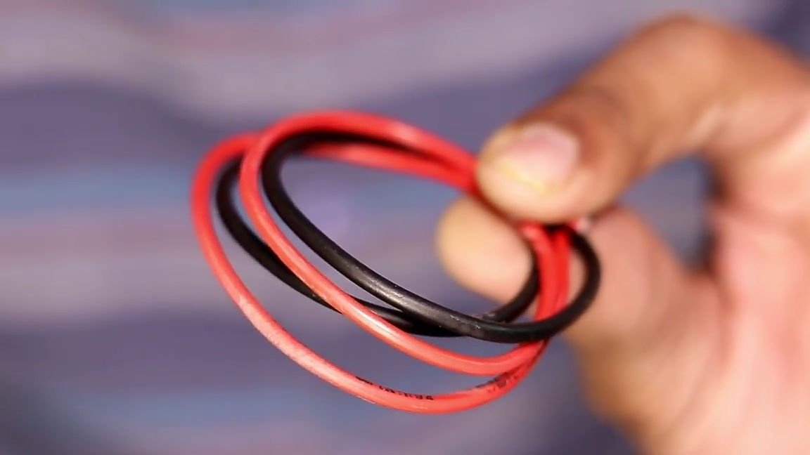
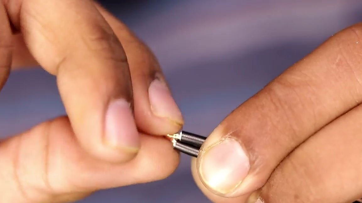
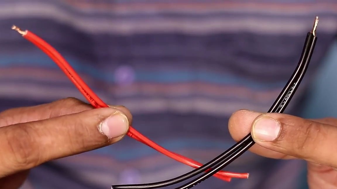
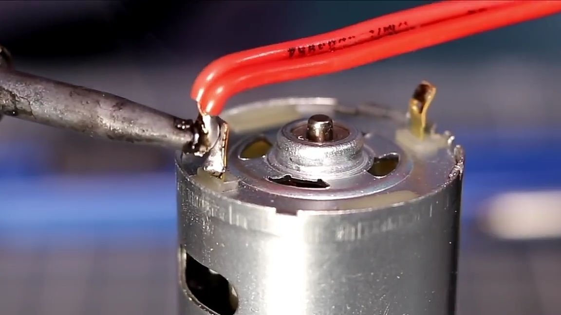
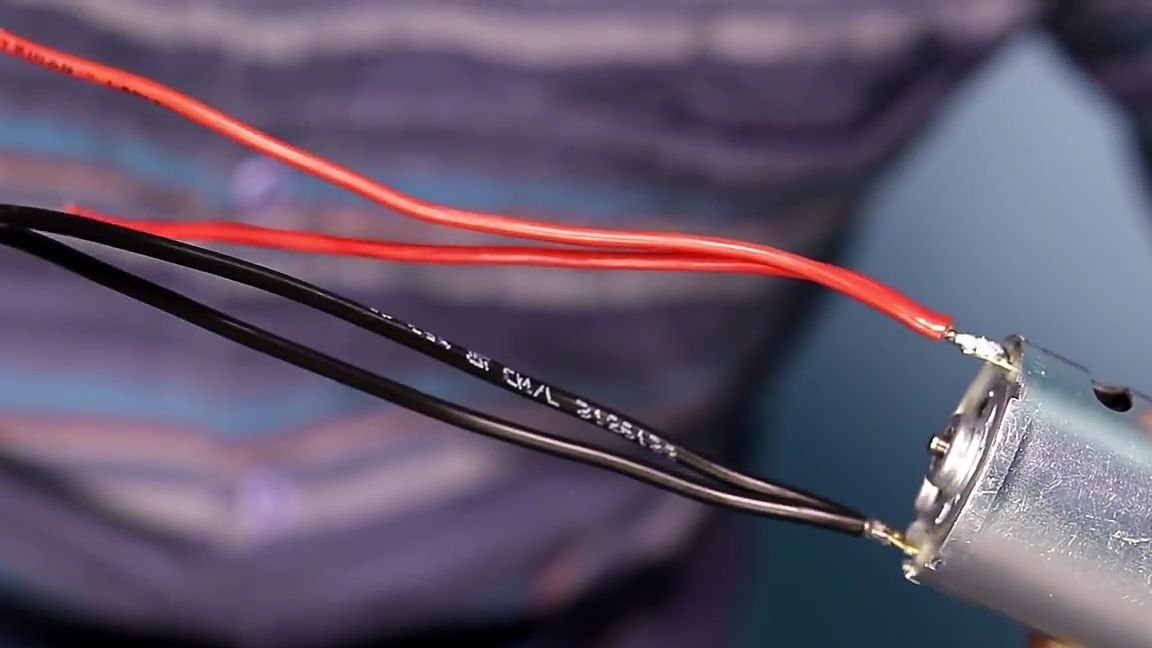
After that, we should prepare the wires for reverse, that is, take the wire and divide it into four identical sections of a length of no more than 15 cm. at the ends, remove the insulation, and connect the four wires into two, connect only on one side, as this is shown in the photo below. Then you should tin all the ends, and the side where the two wires are connected into one, solder to the contacts of the electric motor.
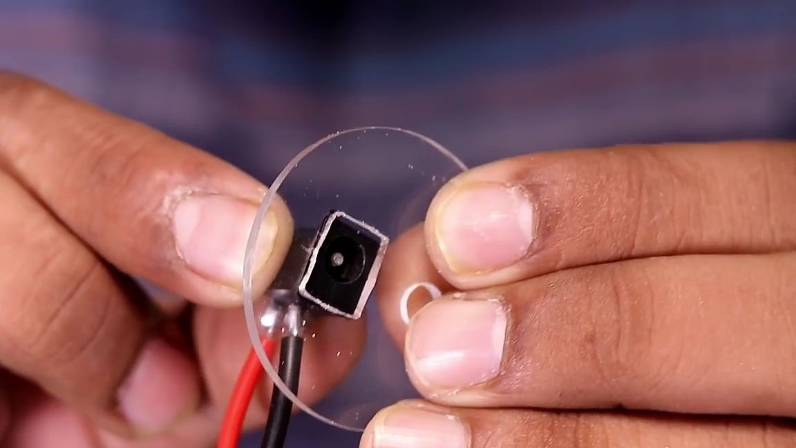
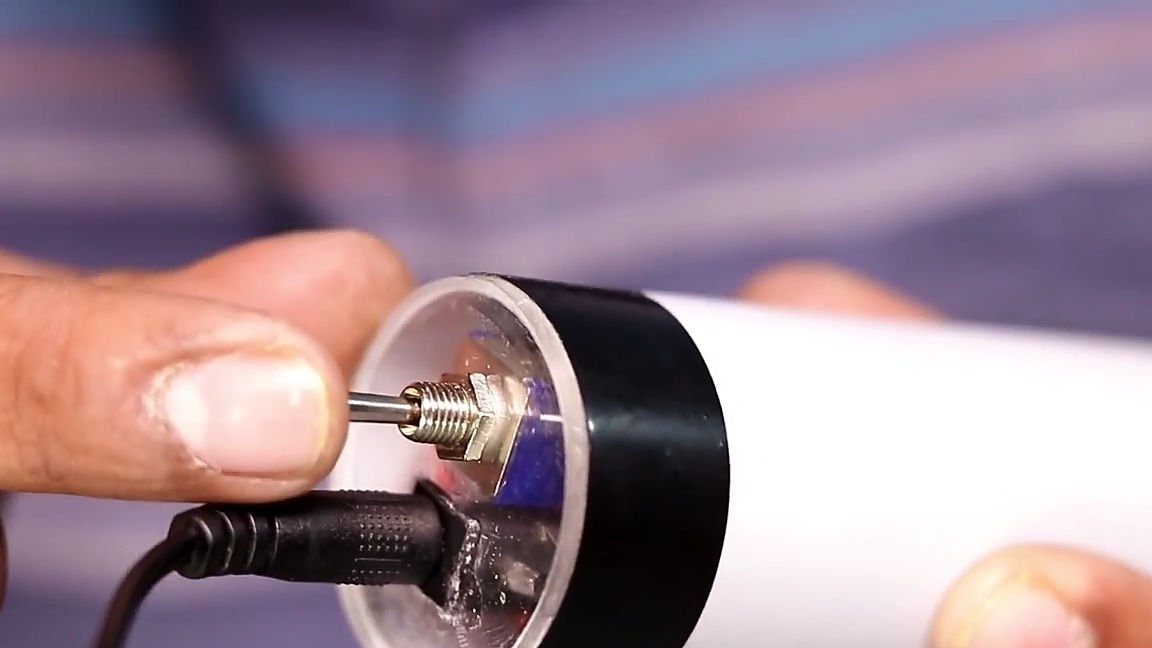
Then we proceed to the preparation of the second circle. To do this, take the power connector and attach it to the circle, circle the marker and make a hole. The hole should be made with a hot soldering iron and finalized with a file. And in exactly the same way you should make a hole for the reverse switch.
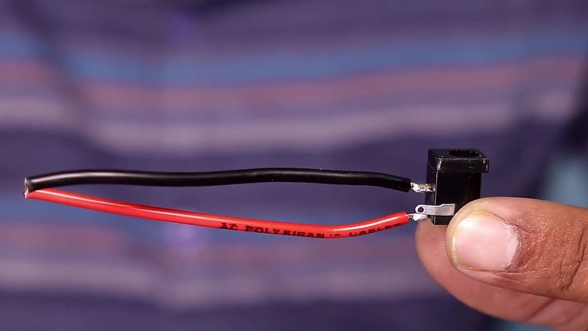
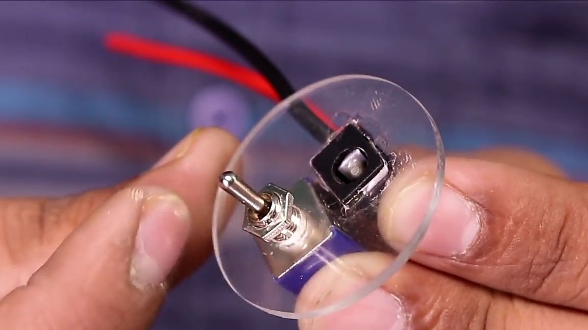
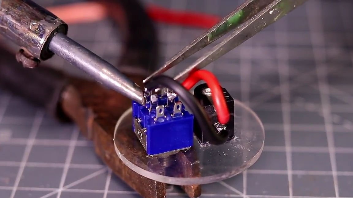
Solder one small piece of wire to the power connector. And we install the connector itself in its seat and fix it with superglue, and then we install the reverse switch and fix it with our fasteners, that is, with a nut. And for starters, solder the wires coming from the power connector, and solder them to the central contacts of the reverse.
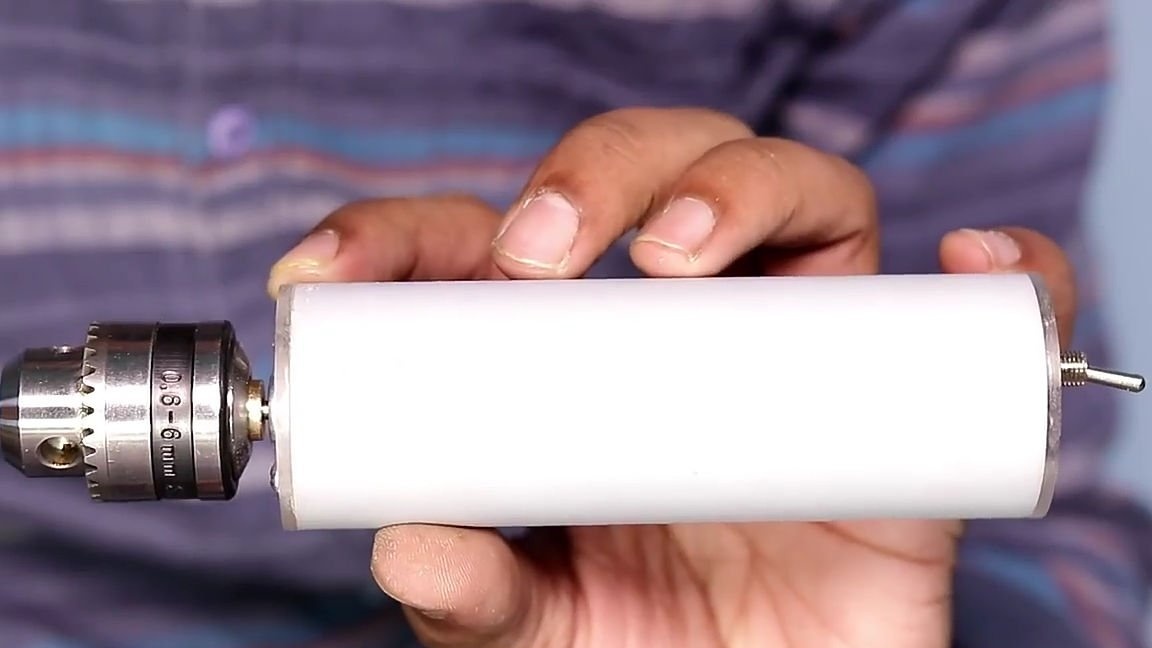
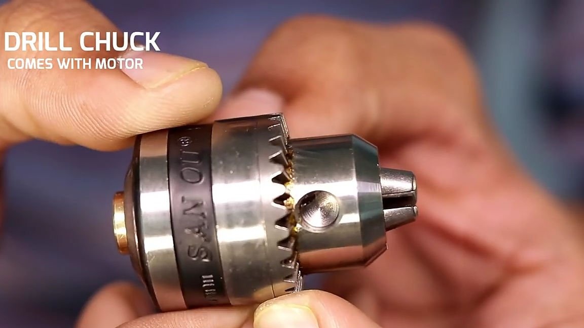
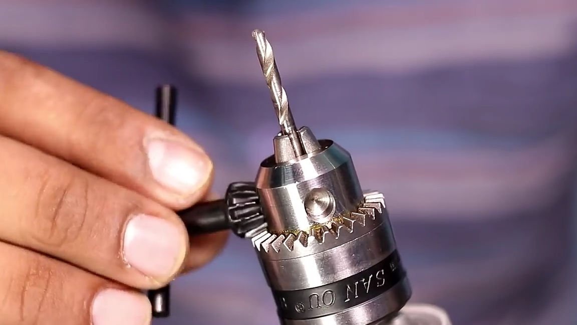
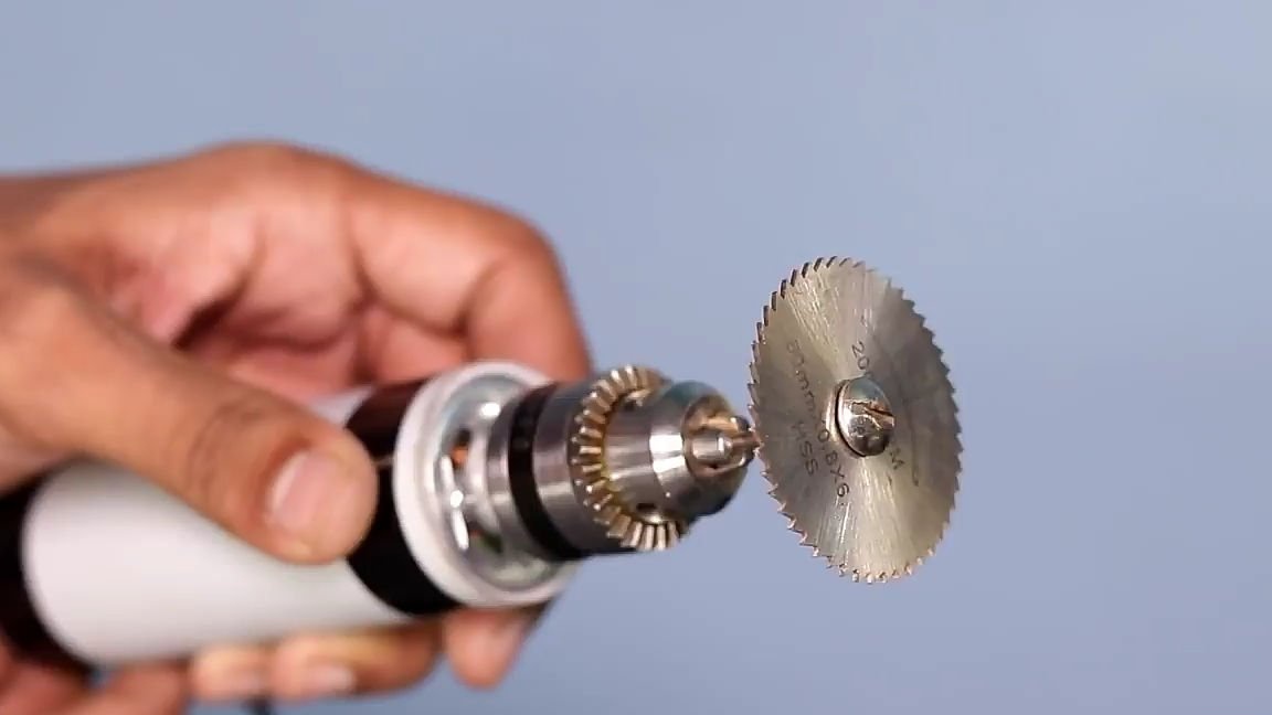
After that, we should install a drill chuck, which can be purchased in any Chinese online store, of any size on any shaft. The cartridge must fit very tightly onto the shaft. It should be pressed, but if you do not have a press, then you can do it with an ordinary hammer, just insert the cartridge, turn the motor over with the cartridge down, and hit the motor shaft without touching the body itself.
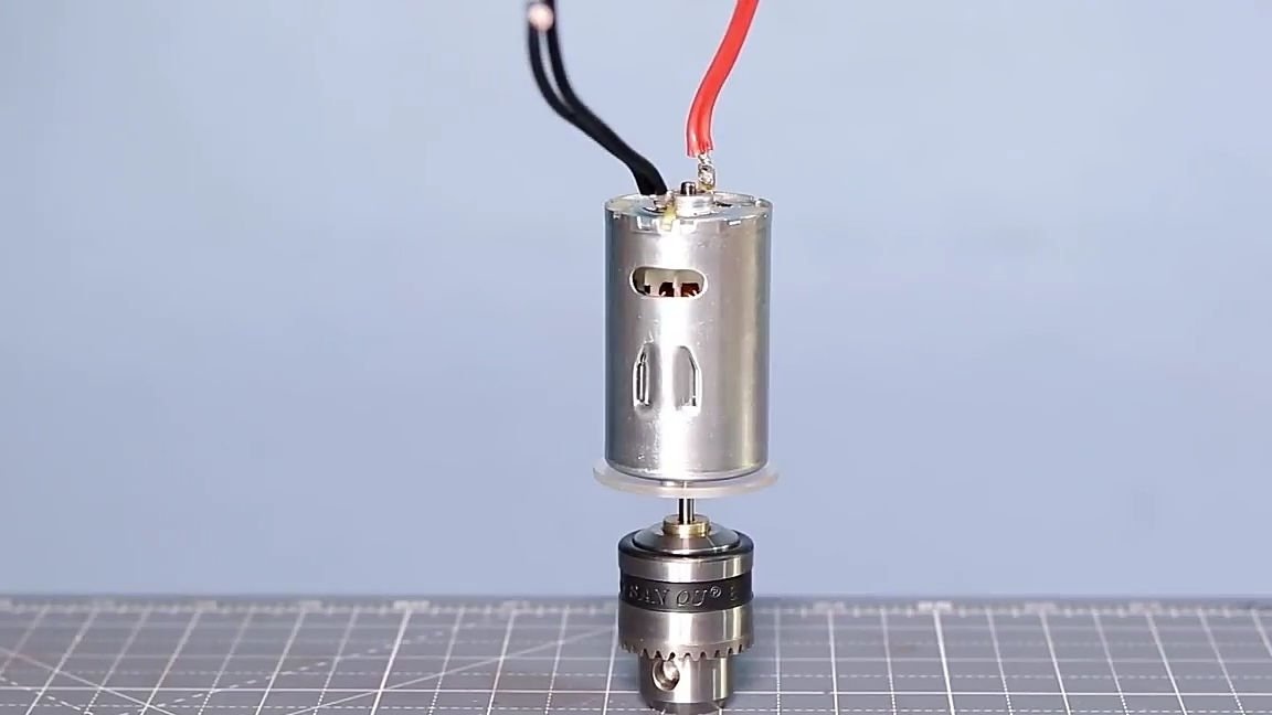
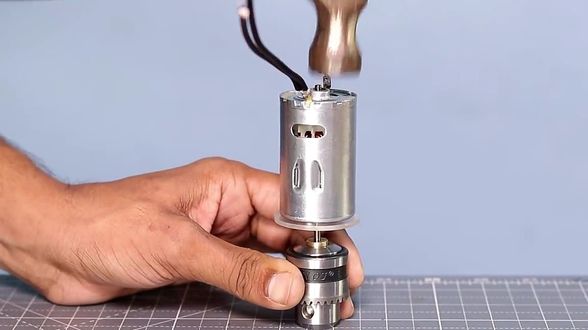
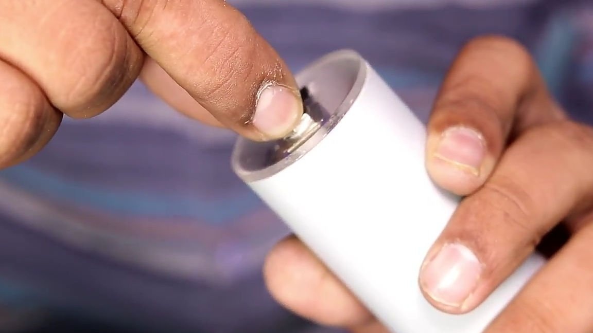
Then we install the electric motor itself in our case, for this we apply superglue to the previously prepared PVC pipe in the indicated place, wait a couple of seconds (so that the glue melts the plastic surface) and glue the motor, as it is shown in the photo below.
Next, solder the wires coming from the electric motor to the reverse switch. It should be soldered in this way, solder one red wire to the upper left contact, and the second red contact to the lower left contact, then in the same way, but only vice versa, solder the black wire.And finally, glue the second circle with super glue.
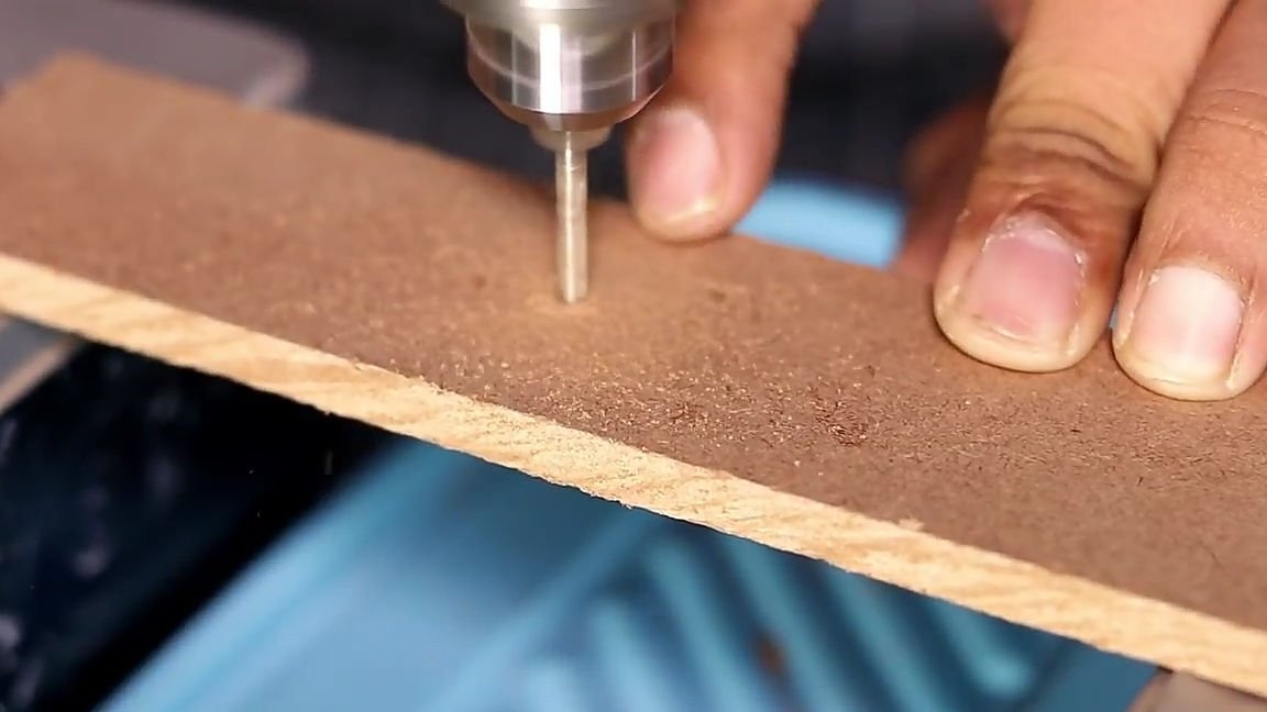
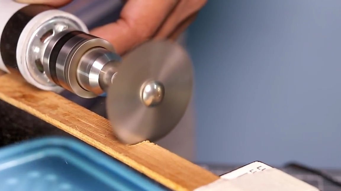
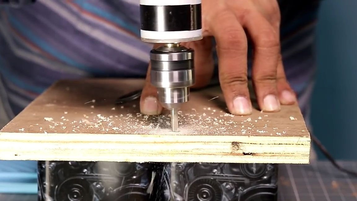
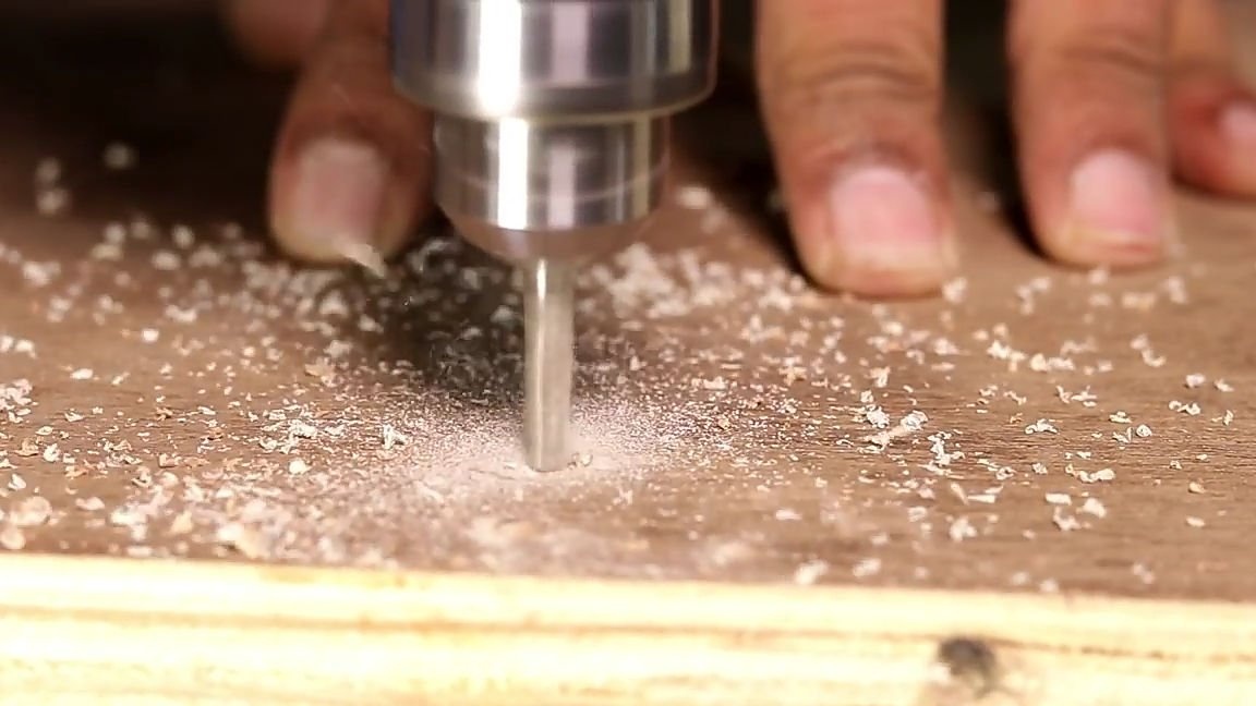
All is ready! It remains only to connect the power and test the homemade (homemade tests you can see in the images below and evaluate its abilities). For this model of drill, you can purchase a wide variety of nozzles from ordinary bor machines, and make full use of homemade for its intended purpose.
Here is a video from the author with a detailed assembly and testing of this homemade product:
Well, thank you all for your attention and good luck in future projects, friends!