
In his previous videos, Roman (the author of the YouTube channel “Open Frime TV”) showed how he independently assembled a soldering iron and a hairdryer, as well as what and where to connect. Yes, at the moment the project has undergone significant changes, and the author decided to share his revision.
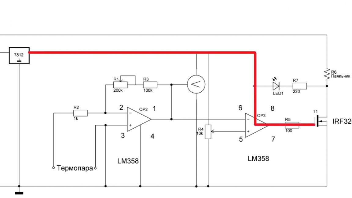
Let's start with a soldering iron. In the previous version, everything was very simple. There is a comparator that compares the voltage with the thermocouple and the set one, and depending on this, the output is zero (0) or plus (+) power.
But such a solution is not very convenient. Just imagine the situation, you need to get a temperature of say 300 ° C. First, the soldering iron is heated to this temperature, and then the hard swing begins. As soon as the temperature exceeded 300 ° C, the soldering iron turned off, fell by 1 degree and it again turned on at full power. As a result of this, almost instantaneous heating occurs and again the soldering iron turns off. Hence, there is no temperature stability.
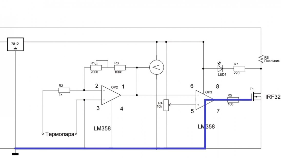
The solution to this problem lies on the surface, it is a familiar PWM signal.
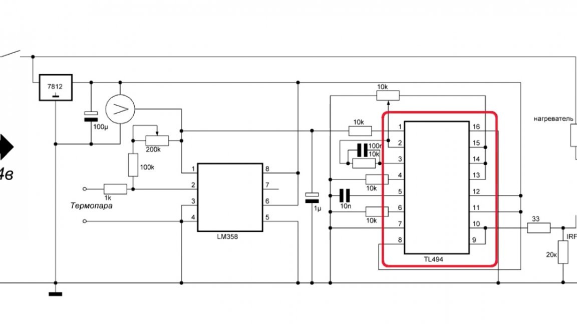
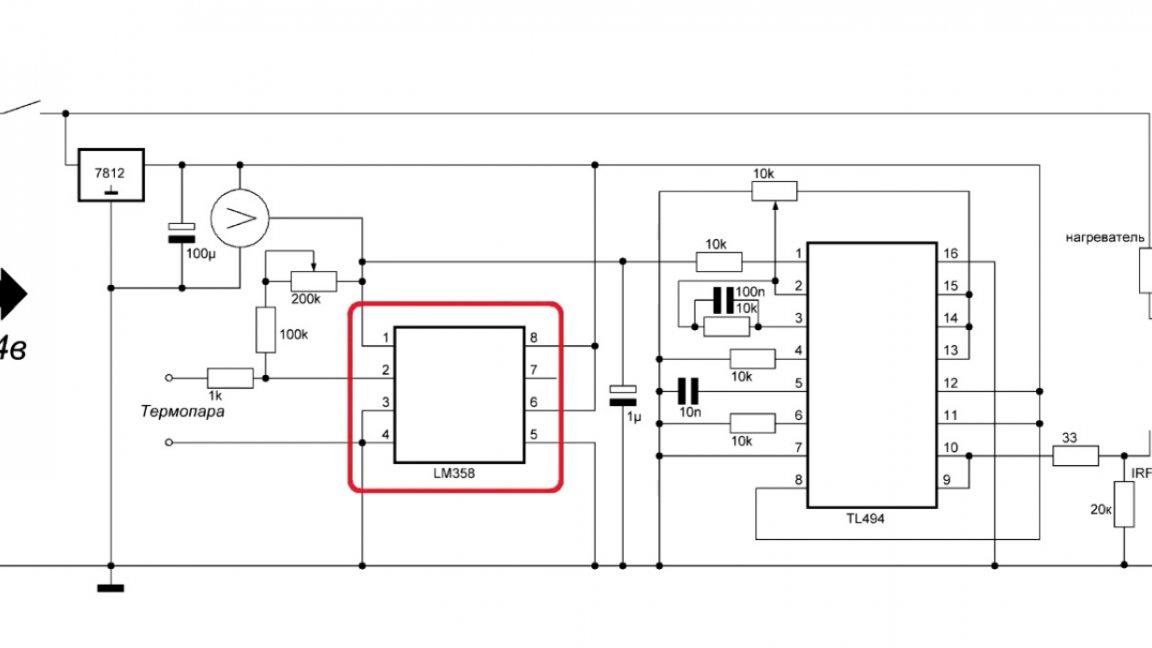
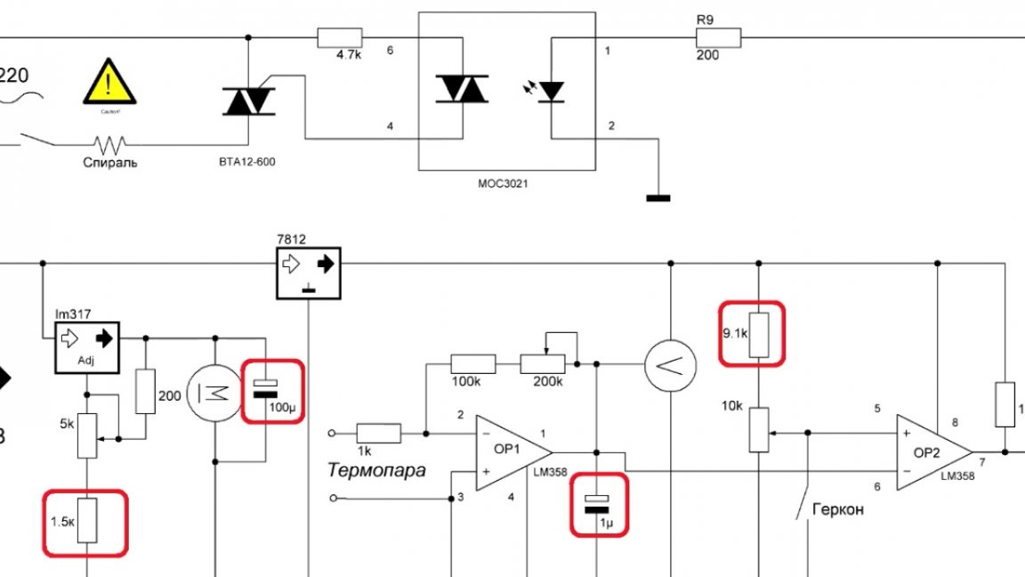
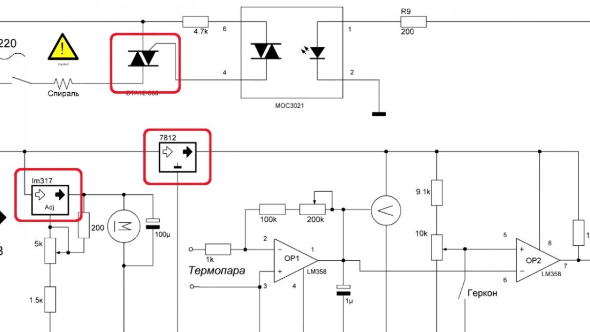
With it, you can keep the temperature pretty accurately. The device diagram in front of you:
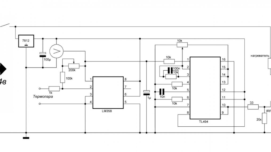
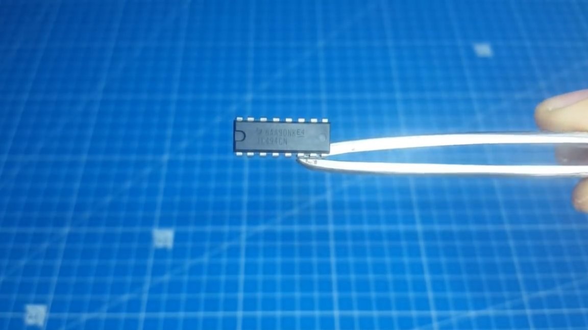
As you can see, tl494 is used here as a PWM controller.
Someone will say that this is too bold, but the author did a lot of experiments, did PWM on both the OS and ne555. The schemes worked, but a little not as I wanted.
Plus, in terms of size, the boards came out more and correspondingly more expensive, since there are more parts, and then there is one chip for 8 hryvnias (about 20 rubles) and a couple of details for it. But such a scheme works like a clock.
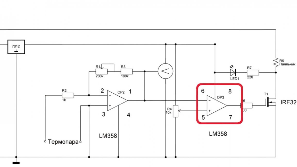
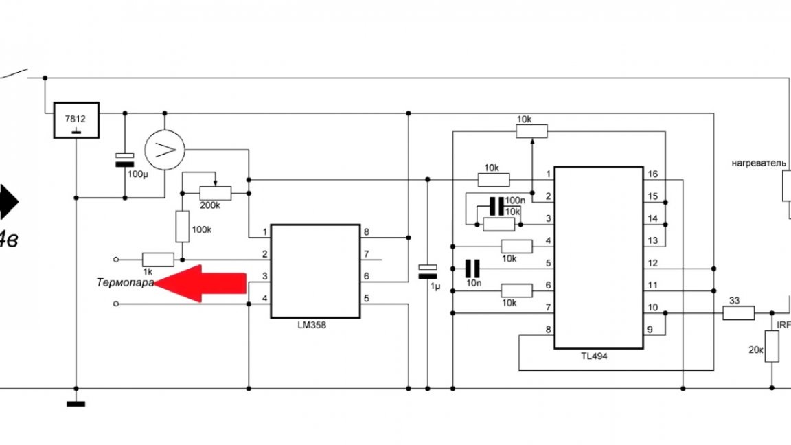
Now let's understand the scheme. The input is the same as in the previous version.
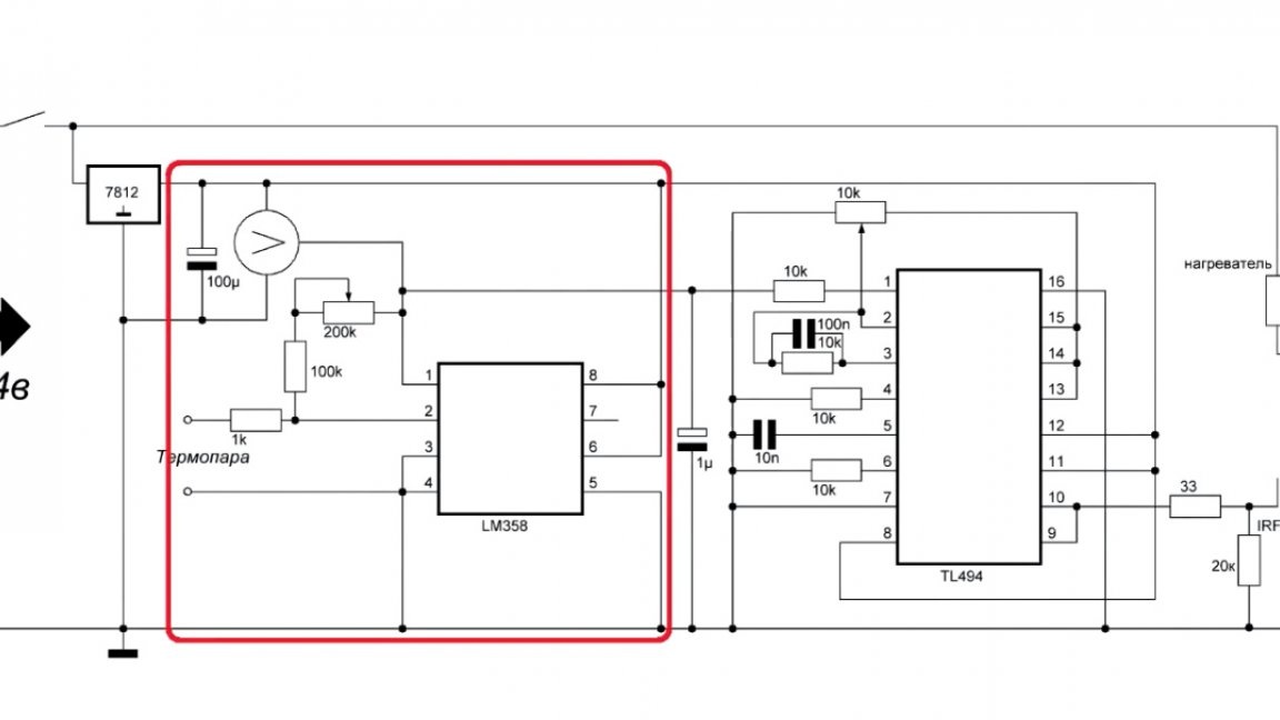
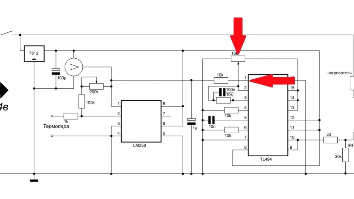
The LM358 amplifies the signal from the thermocouple, and now this voltage is supplied to the tl494 non-inverting error amplifier, and the reference voltage from the variable resistor is applied to the inverting input of the amplifier.
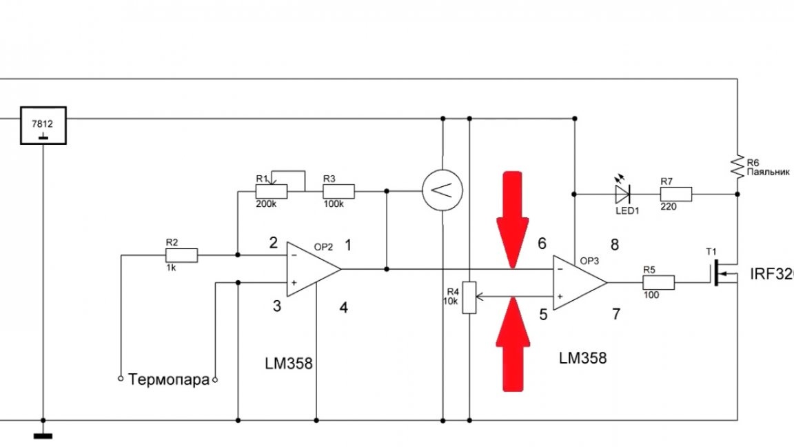
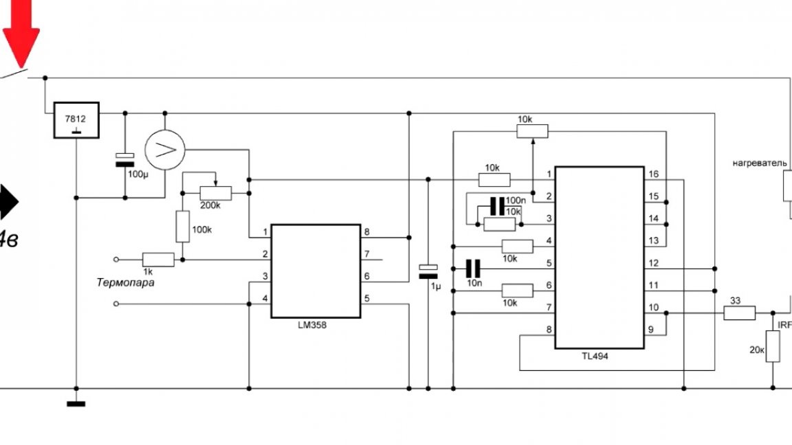
We start the review from the moment the circuit is off and the soldering iron is cold. Turn on the circuit.
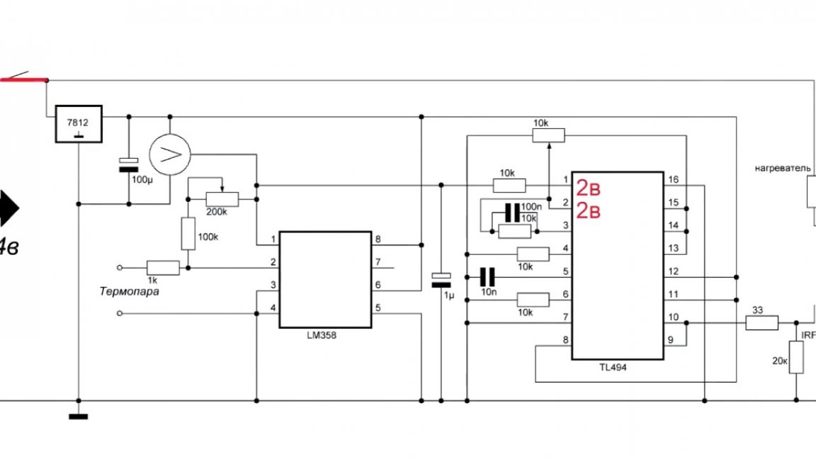
At this moment, the output voltage of the thermocouple is the minimum voltage, therefore, the voltage on the first leg of the microcircuit is lower than on the second. An error amplifier that monitors and does not affect the signal.
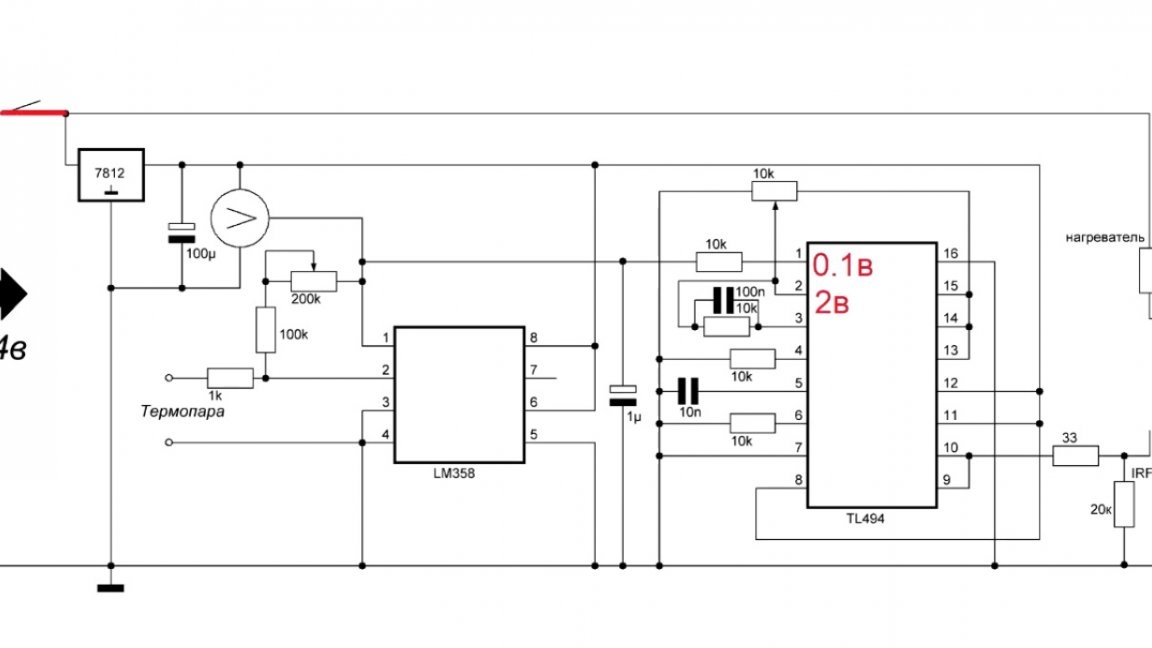
PWM microcircuit maximum, there is an intensive heating of the soldering iron. After some time, there comes a moment when the stress on the first leg is compared with the stress on the second leg.
Then the error amplifier sees this and begins to reduce the PWM signal, thereby keeping the temperature in equilibrium. So, with the principle of operation of this scheme figured out, you can go to the second scheme, namely, control the hairdryer.
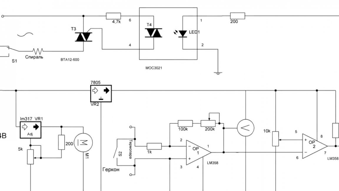
The author left this scheme as in the first version. True, I added a few elements, but this is a trifle.
And also fixed the operation of the reed switch. In the previous version, it did not work, now, if you close it, the spiral turns off.
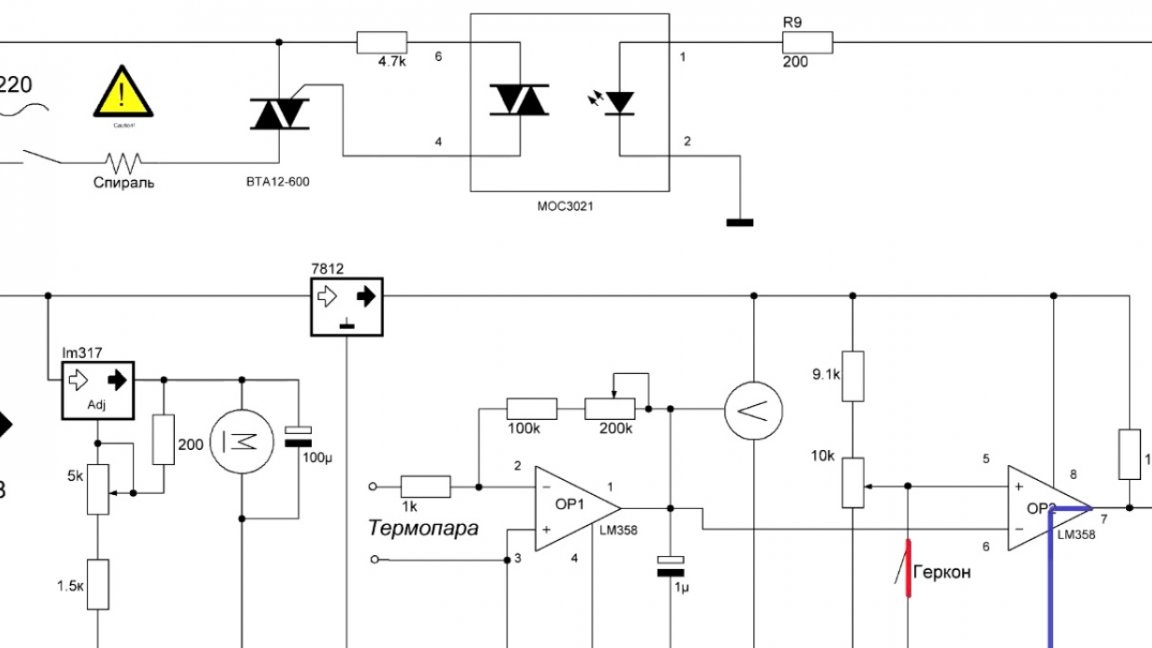
Everything is more stable here because the hairdryer has a lot of power, and, consequently, a lot of inertia. The temperature value is pretty good.
A few words about the power supply. For this station, you can use any 24V power supply and 3A current.
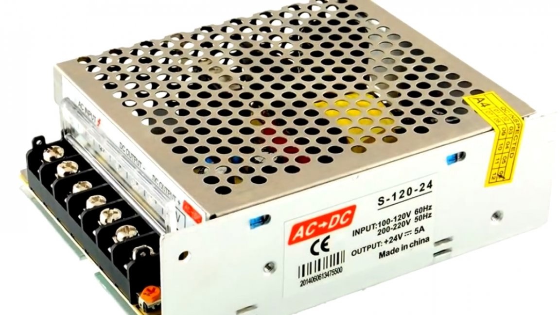
At the very beginning, the author wanted to put a simple block on ir2153, but conscience did not allow it, so this block was purchased for 24V and current 4A with stabilization of the output voltage, it will be more correct.
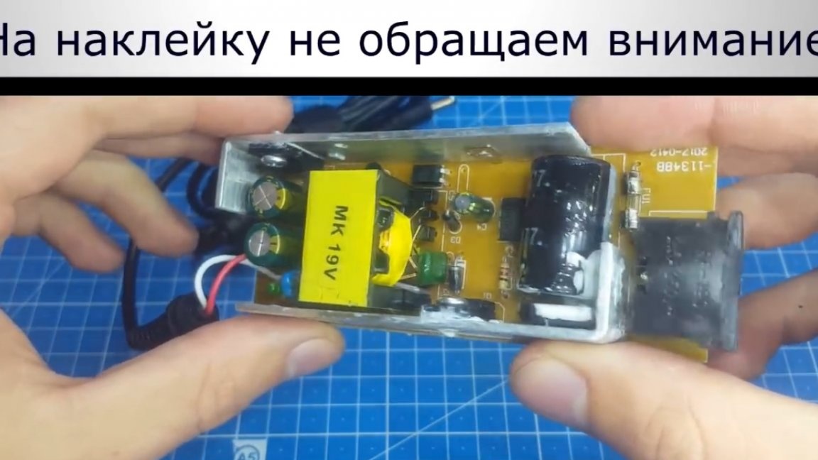
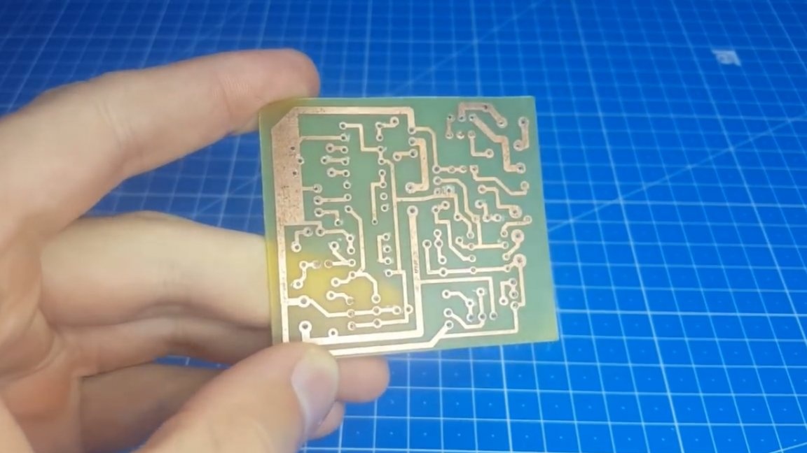
If you do not have any drops in the network, then you can do the block on Ir2153. The next step is a circuit board.
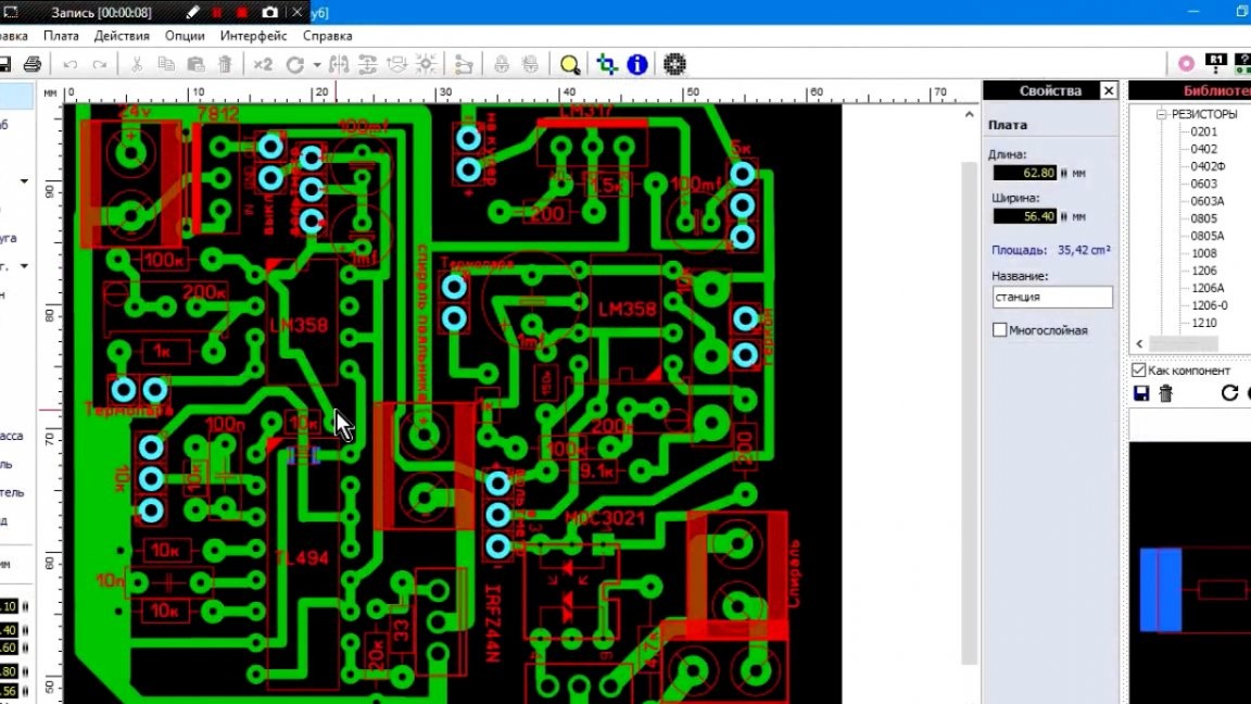
Then the author tried to place everything very compactly. It turned out pretty well, only 2 jumpers, one smd, the second ordinary.
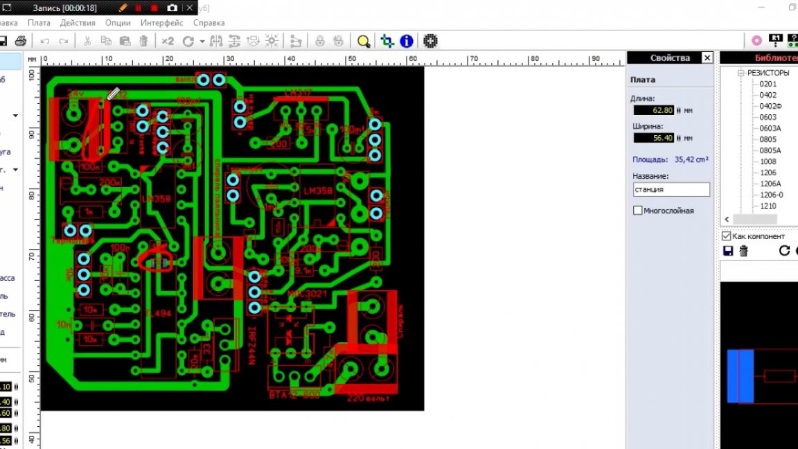
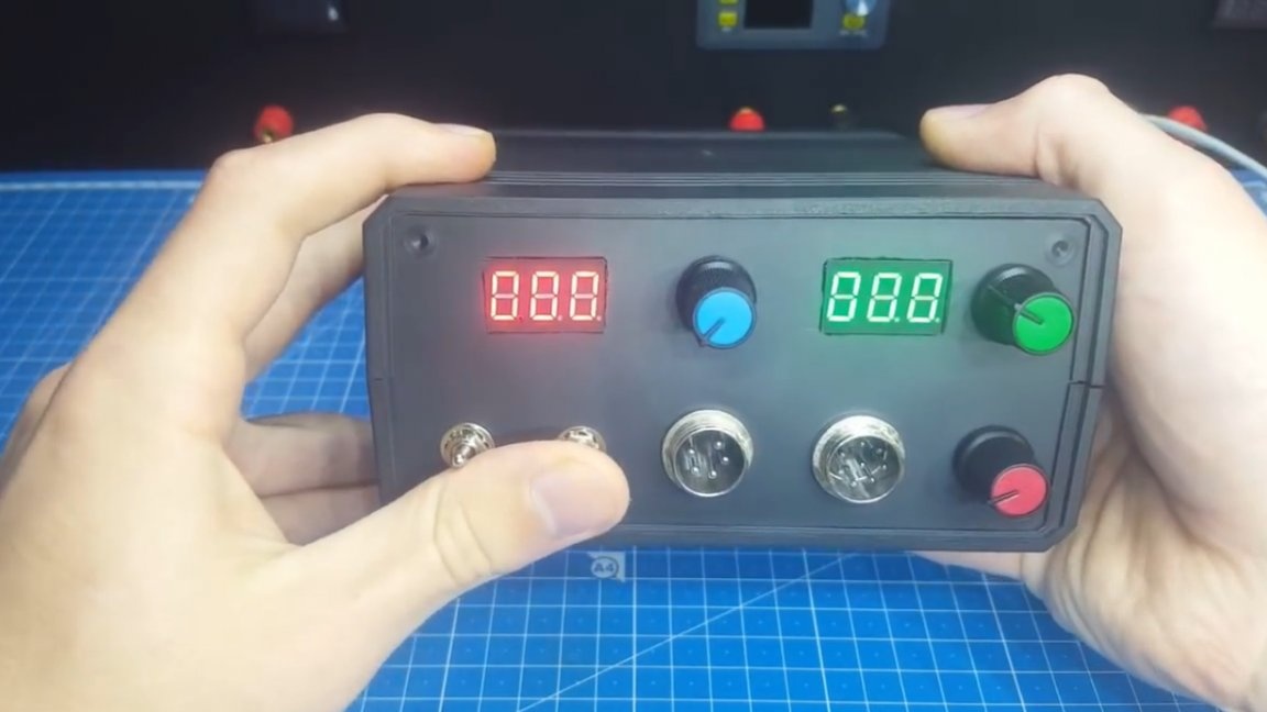
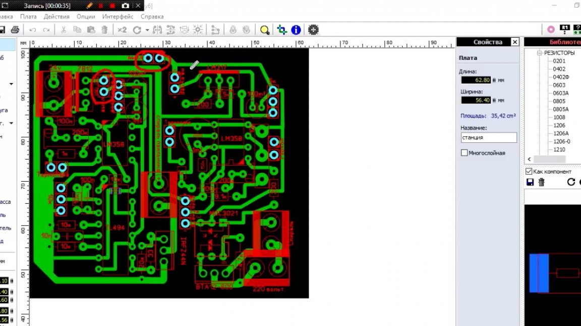
To connect all peripheral devices, the author made such connectors and signed everything.
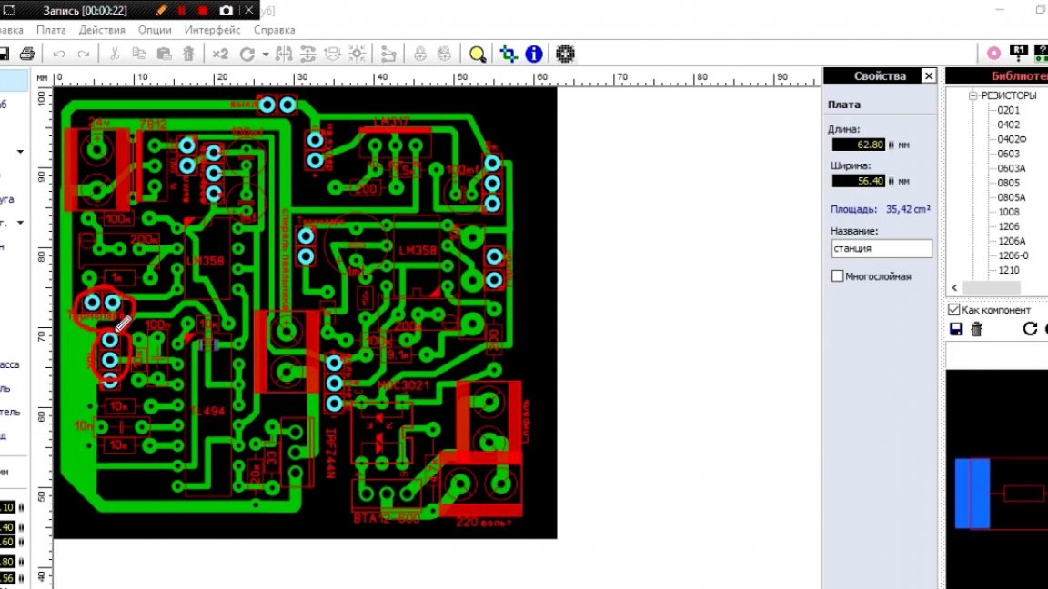
Where the asterisk on the voltmeter is a measuring contact, plus and minus, respectively. Switches are needed so that the hairdryer and soldering iron can turn on independently.
The board is ready, now you can solder it.
First of all, we collect the part that is responsible for heating the soldering iron.
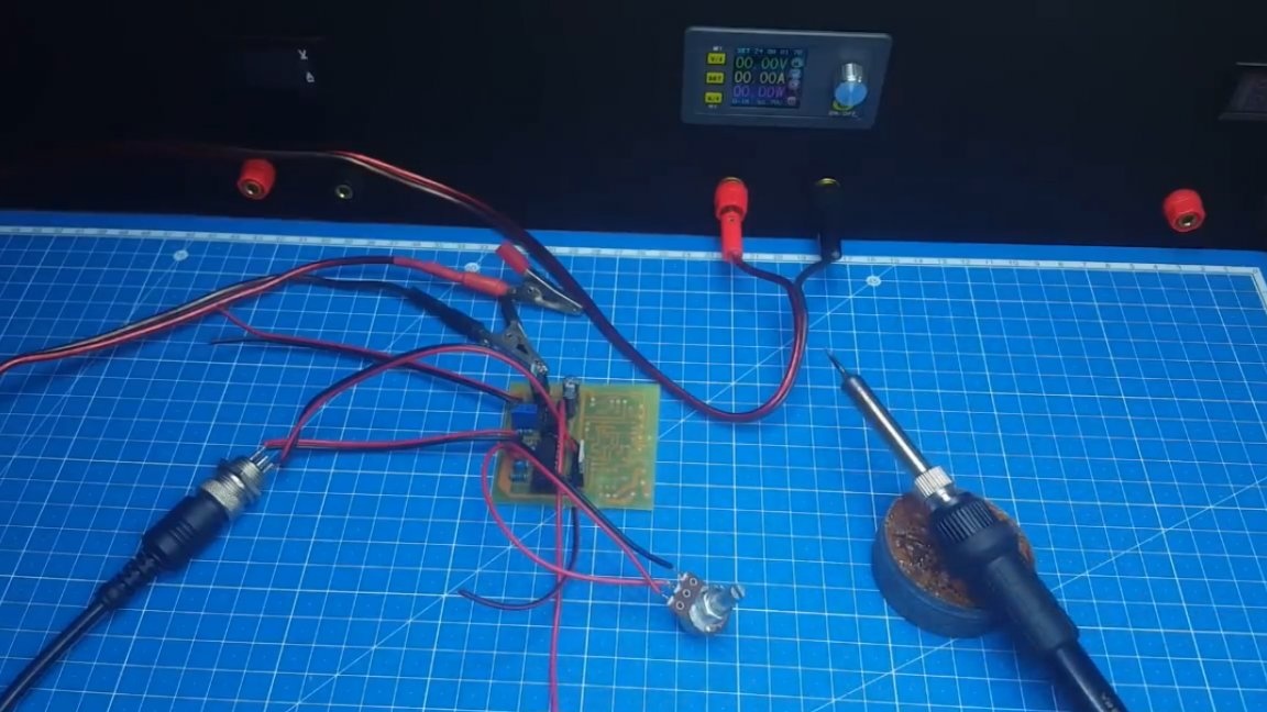
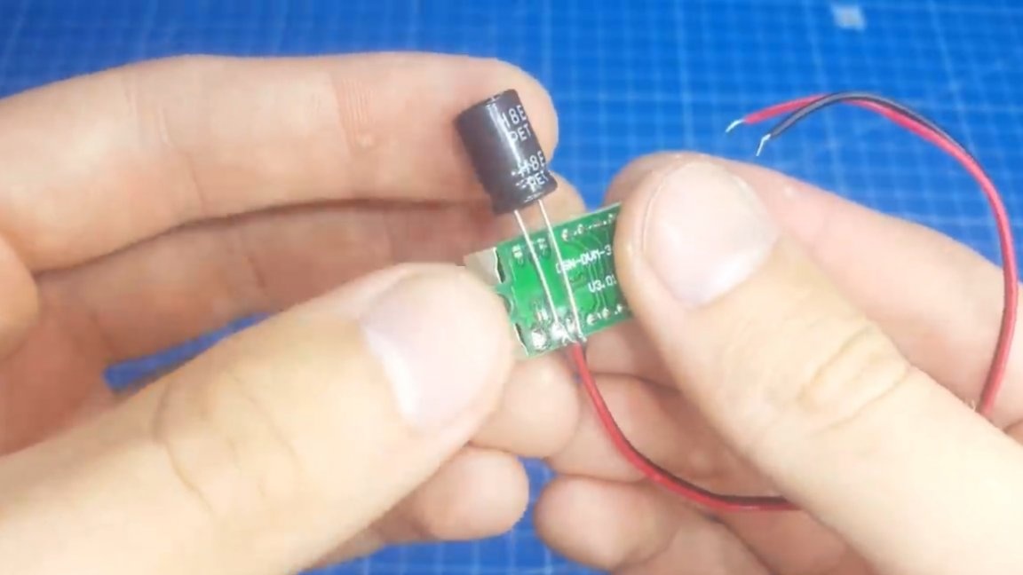
When everything is connected, we make a test run, but as you may have noticed, one important element is missing here, namely a voltmeter for temperature control. The author in his previous homemade products already used this Chinese voltmeter as a meter:
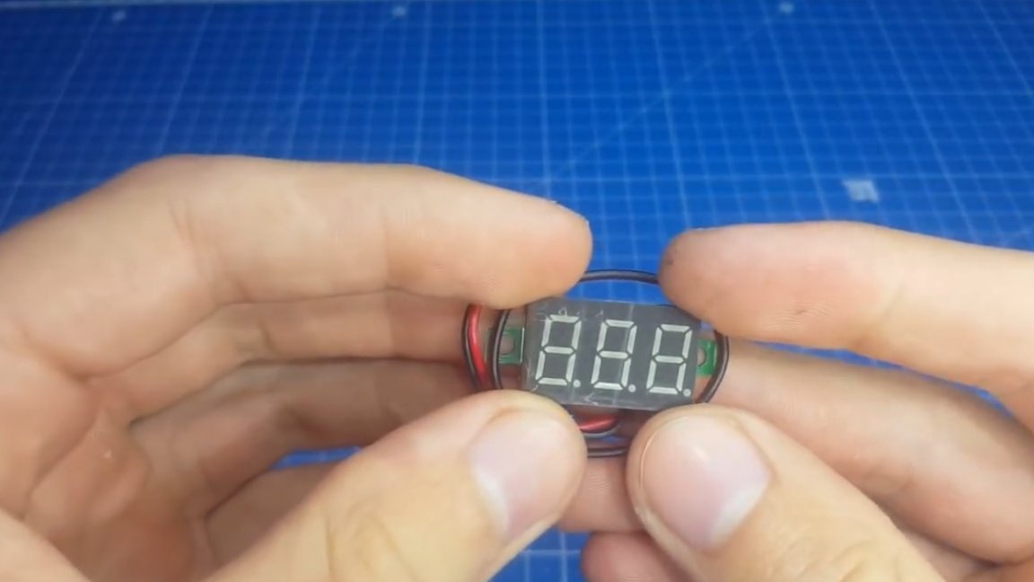
He has 3 outputs, 2 of them are power, and 1 measuring. Such voltmeters are most often sold with 2 wires, they simply have a supply and measuring wire.
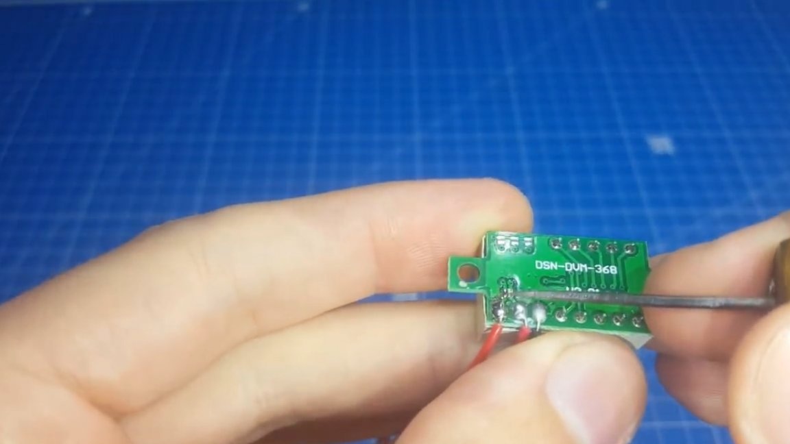
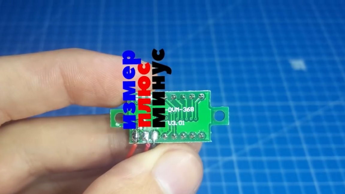
We need to disconnect them and get the necessary 3 conclusions. Now we connect a voltmeter and you can test and calibrate this board.
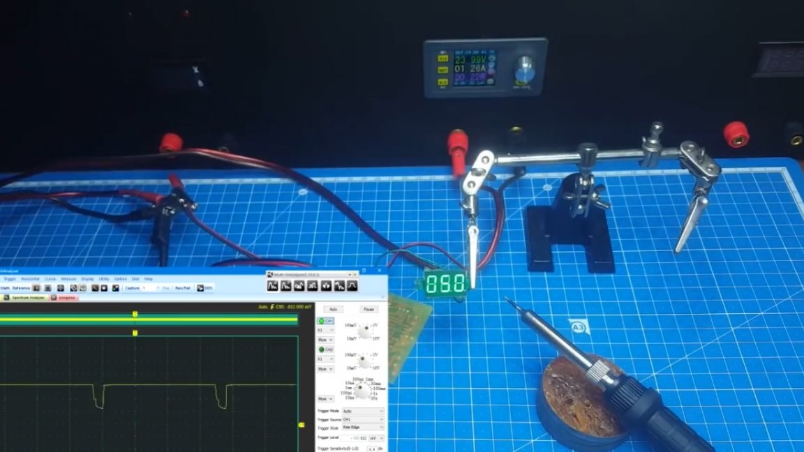
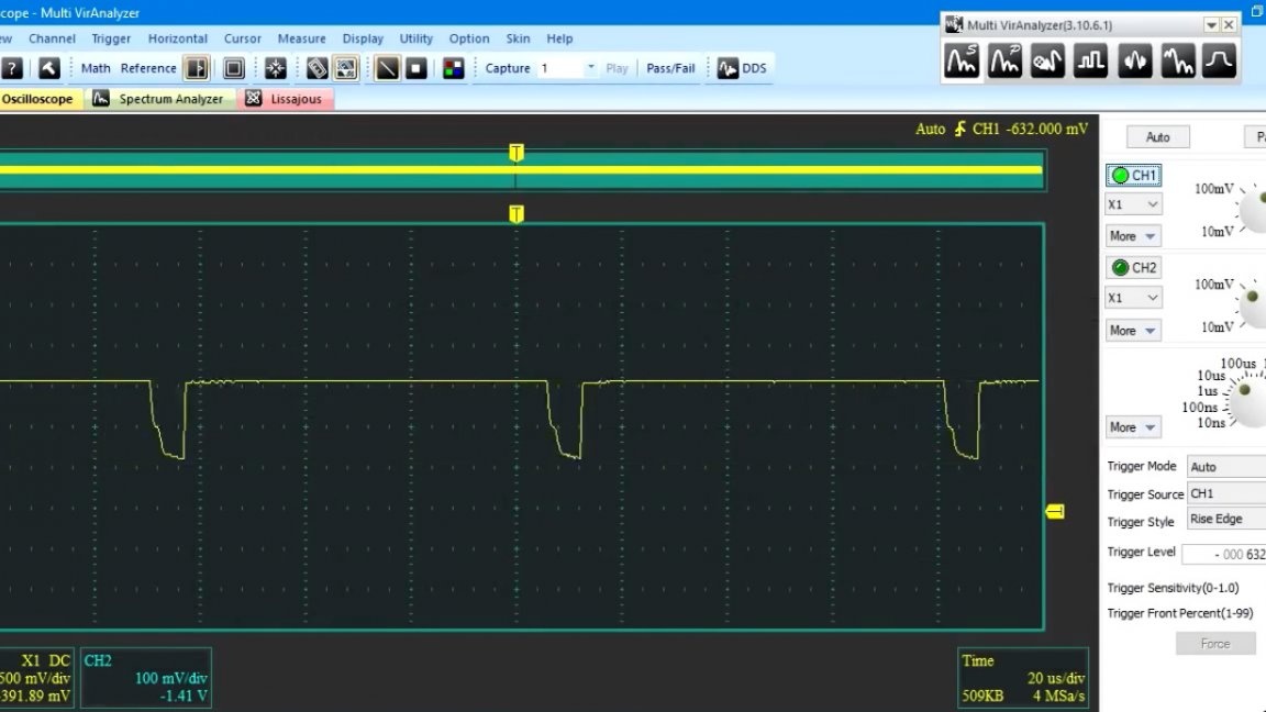
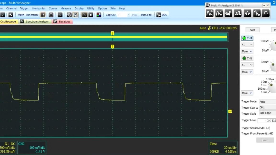
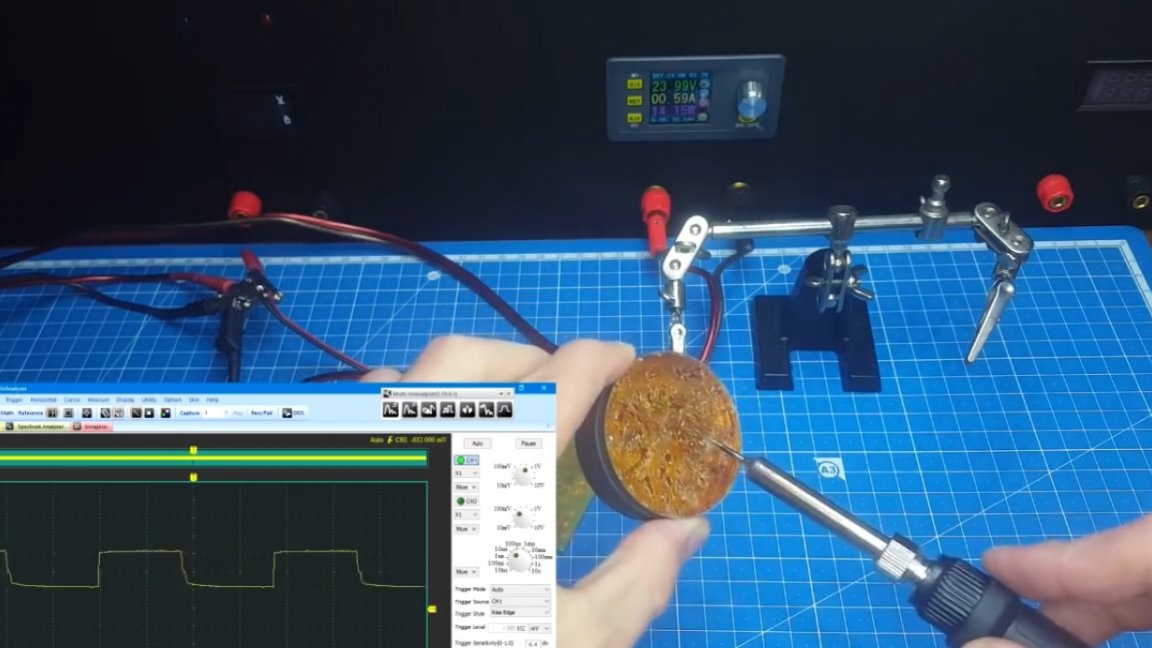
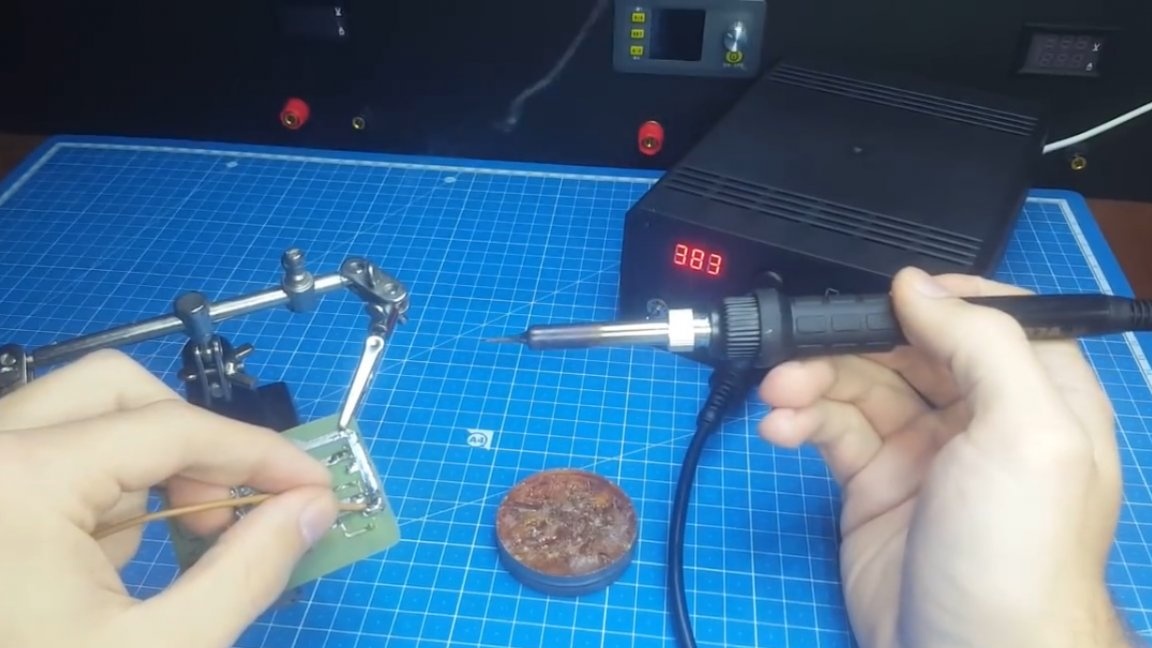
Before turning on, the author connected the oscilloscope probe to the transistor gate to demonstrate operation.
As you can see, the output is the maximum PWM, until the soldering iron reaches the set temperature. Then the PWM begins to decrease and, consequently, the consumption drops, this can be seen by the wattmeter on the power supply.
Now let's do the calibration. For this we need a multimeter, a thermocouple and a screwdriver. Using a screwdriver, we rotate the tuning resistor and compare the readings on the voltmeter and multimeter.
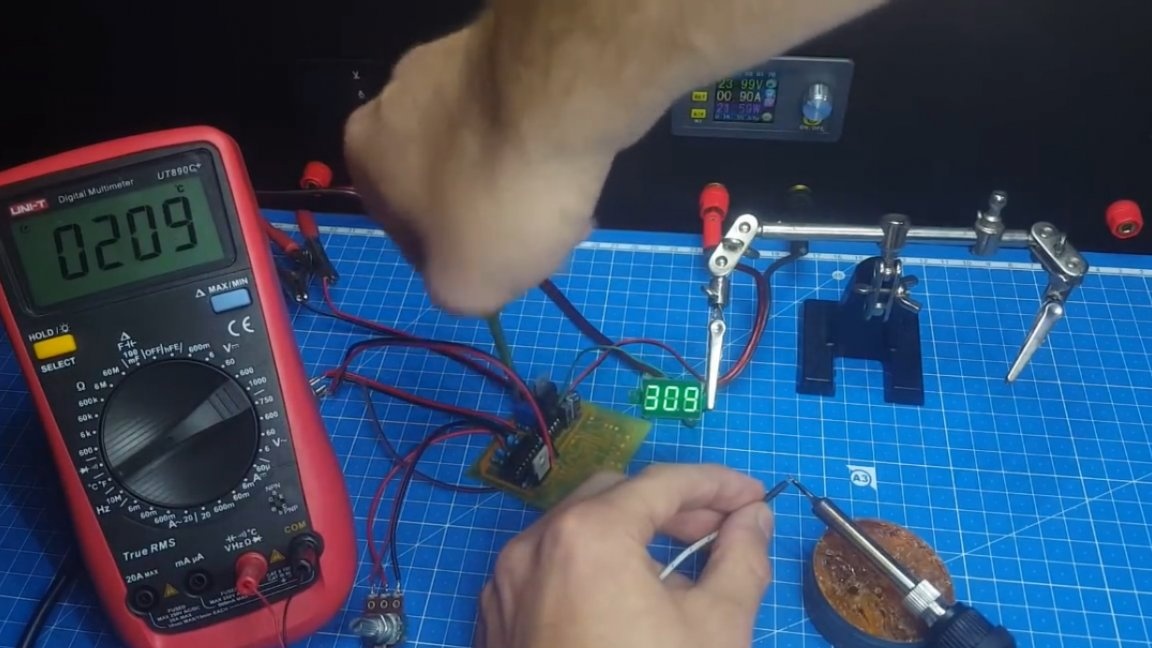
When they caught up - calibration is complete. For reliability, you can turn off the soldering iron, let it cool and repeat the calibration. If your values decrease during heating, then the thermocouple is connected incorrectly.
The author also encountered a problem, when powered by a block on an IR2153 chip, readings on a voltmeter started to jump. This was most likely due to interference. The solution is very simple. It is necessary to solder a 100 uF capacitor for each voltmeter in parallel with the power supply.
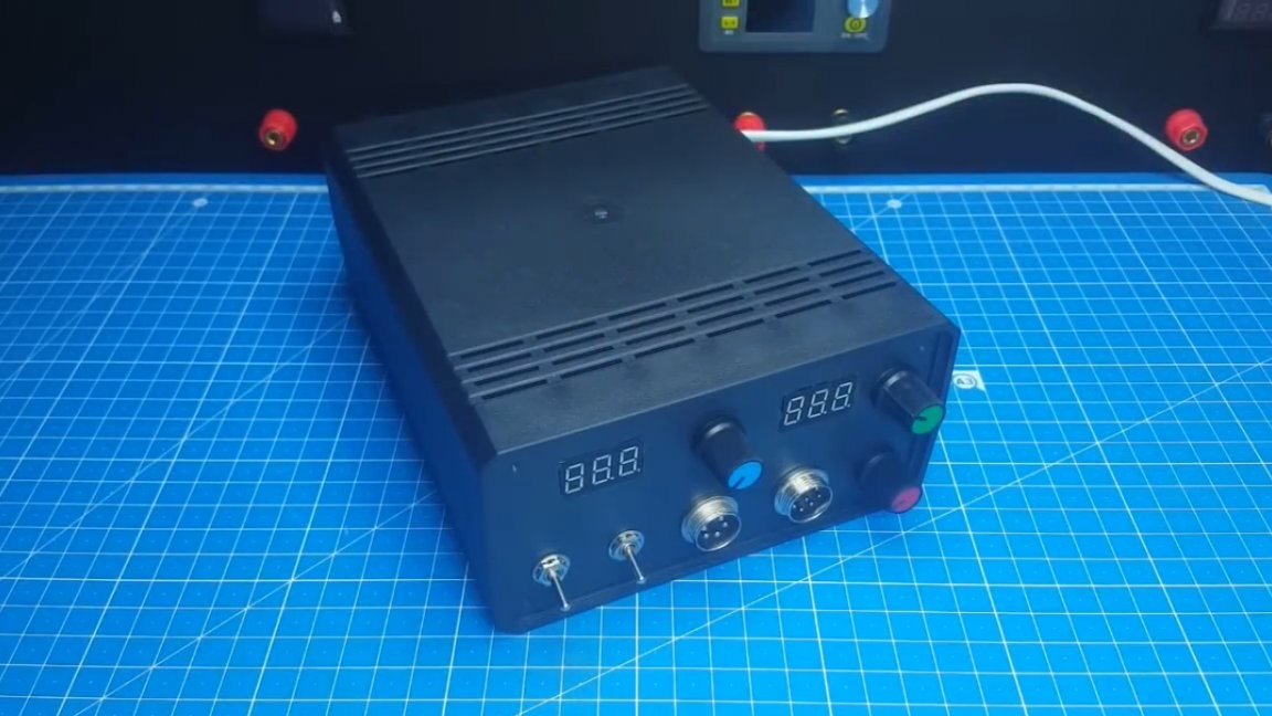
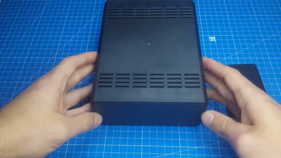
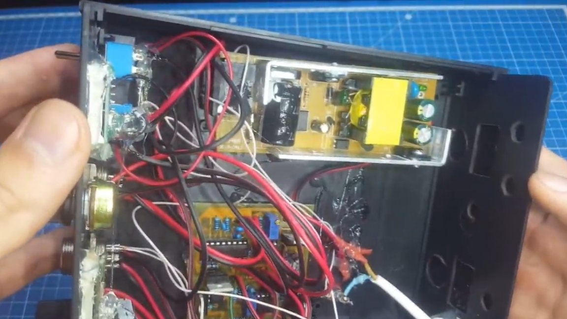
When everything is checked, solder the rest of the circuit. We also check it and calibrate. The setup process is identical, just do not forget that the circuit is under mains voltage. When the scarf is ready, it is necessary to prepare the case. For this, the author uses this plastic box:
The most important thing, according to the author, is to make a beautiful front panel.
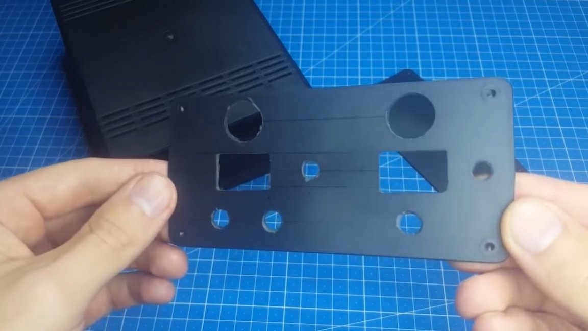
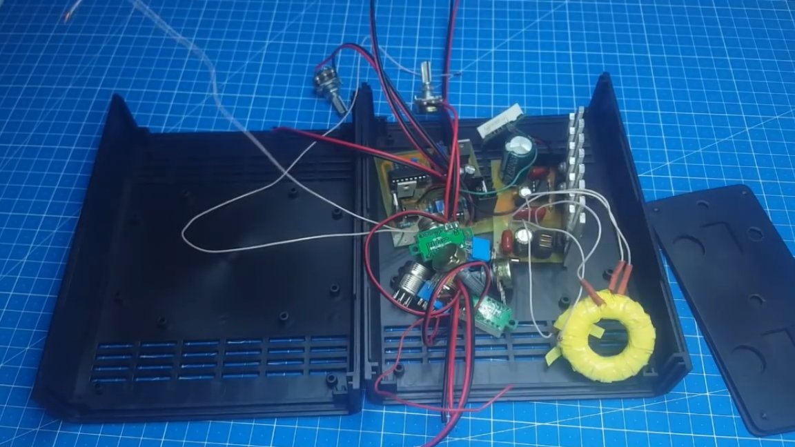
As you can see, the author made holes for all the elements and now it remains to place all electronics in the case. When installed in the case, as always, there was a hot glue, but it turned out pretty neatly.
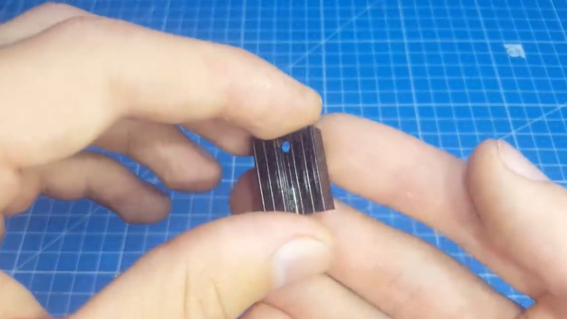
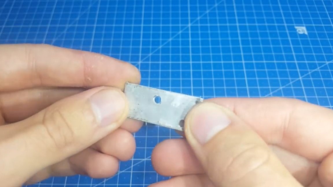
And finally, another important point, which parts of the circuit are heated. These are only 3 elements: 7812 lm317 and triac.
On lm317 and the triac, the author picked up such radiators, factory ones.
And on 7812 it was limited to an aluminum plate.
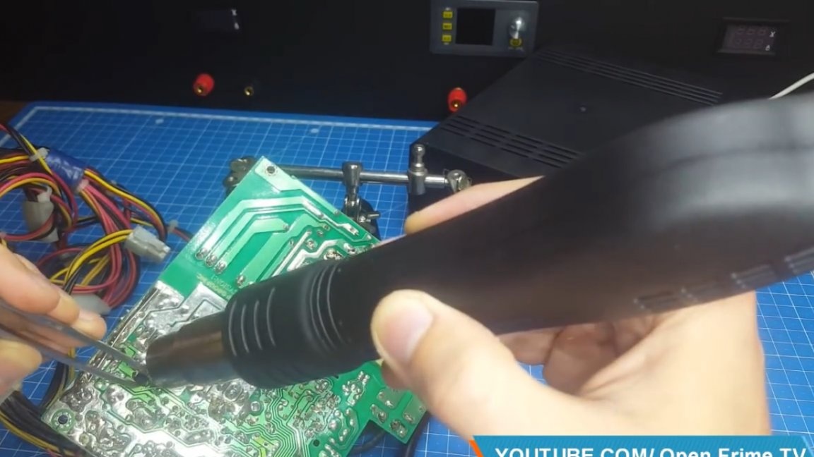
Well, at the end of the final test. We check the soldering iron first.
Well, everything is gorgeous, the temperature is stable during the soldering process and solders perfectly. Now turn on the hair dryer and try to solder some smd part.
And here, too, no problem. The soldering station did its job.
Thank you for attention. See you soon!
Video: