

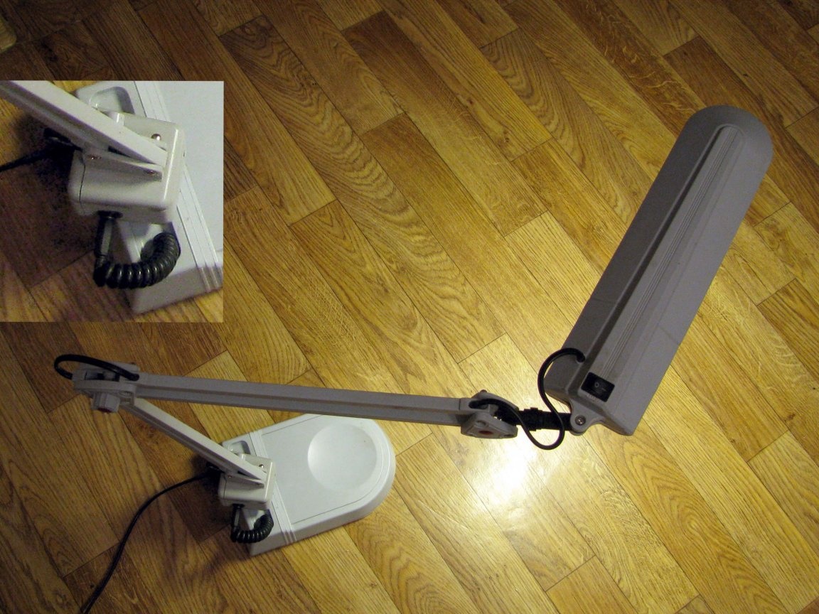
Surely, at least once, but you saw just such a table lamp, more often, similar designs are used for manipulations in beauty salons.
However, in the usual home life, such a lamp is very convenient.
Since I spend enough time on a laptop, I had just such lighting on a rather long tripod. Only here it emits cold white light (CW), I do not find it comfortable. The lamp worked for me for more than a year, and I began to suspect that soon, the life of the fluorescent lamp would come to an end, and I ordered a coil of LED strip in advance. The tape came, and I just had to wait for the lamp to burn out - which happened a few days later.
I suggest you to remake this very convenient design with me on:
- its use with LED strip;
- to think (and realize) about what new qualities this lamp can acquire;
- slightly repair the rotary lamp assembly;
- dream a little, what else could be added, if desired, to an already finished lamp.
Disassembly
.It was not difficult — disassembling is always easier. Pay attention to the massive throttle that was hiding in the cubic cavity of the vertical rotary assembly of the fixture system of the lamp. I got rid of it, but of course I didn’t throw it away.
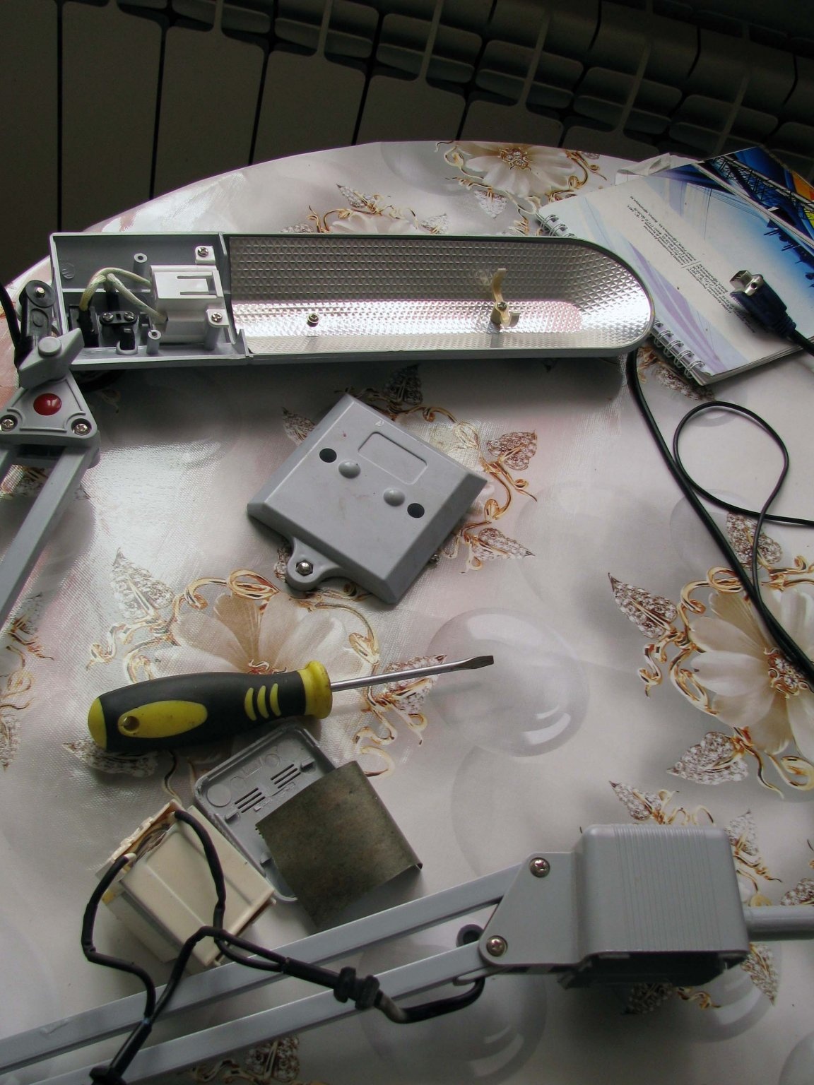
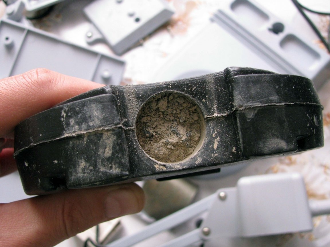
In the lamp stand, a plastic container with cement poured into it was found, it pleasantly surprised me - I expected to find a bag of sand. Of course, this weighting agent will have to be replaced with something. Looking ahead, I’ll say that at that moment, I was leaning towards the sand, but a replacement was found.
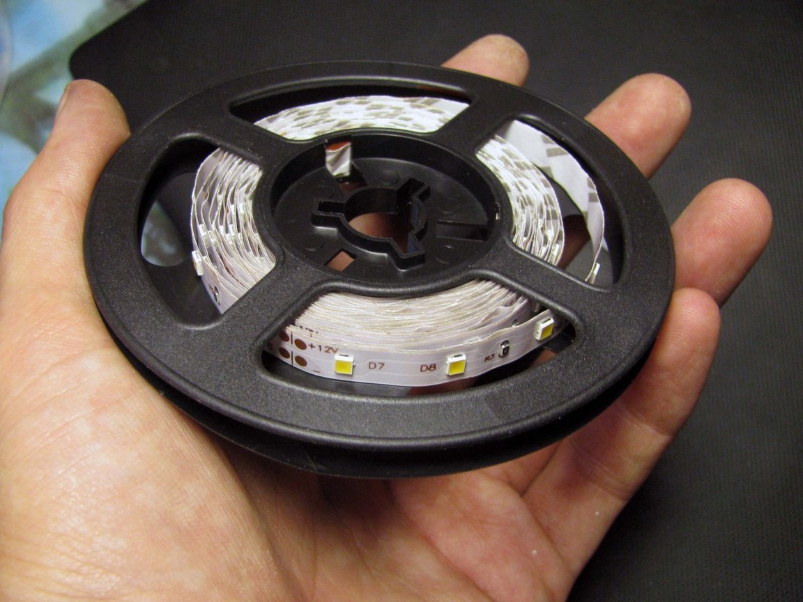
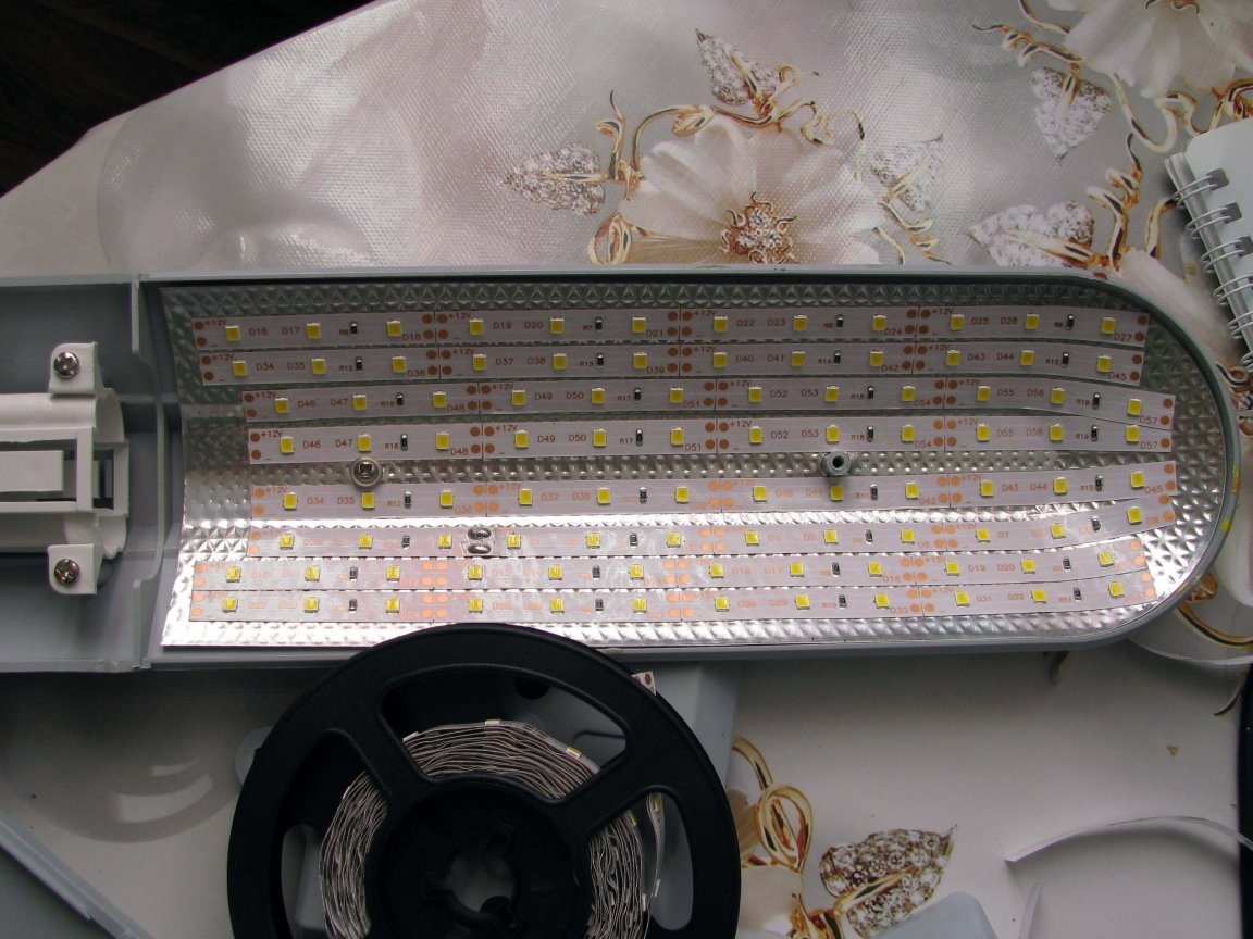
The reel itself with a tape on 2835 LEDs. The choice was not random. I did not want too much power (brightness), because I would have to think about removing significant heat. I also did not want to complicate the designs with dimming - since I do not like long-term construction. And the tape must be WW - a warm white glow.In general, I bought exactly what I wanted.
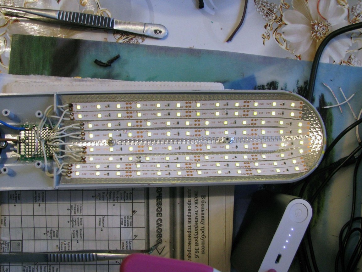
The tape was cut into 8 segments, and glued with a sticky layer to the standard reflector.
Then I was depressed, realizing that how much I would have to solder ..
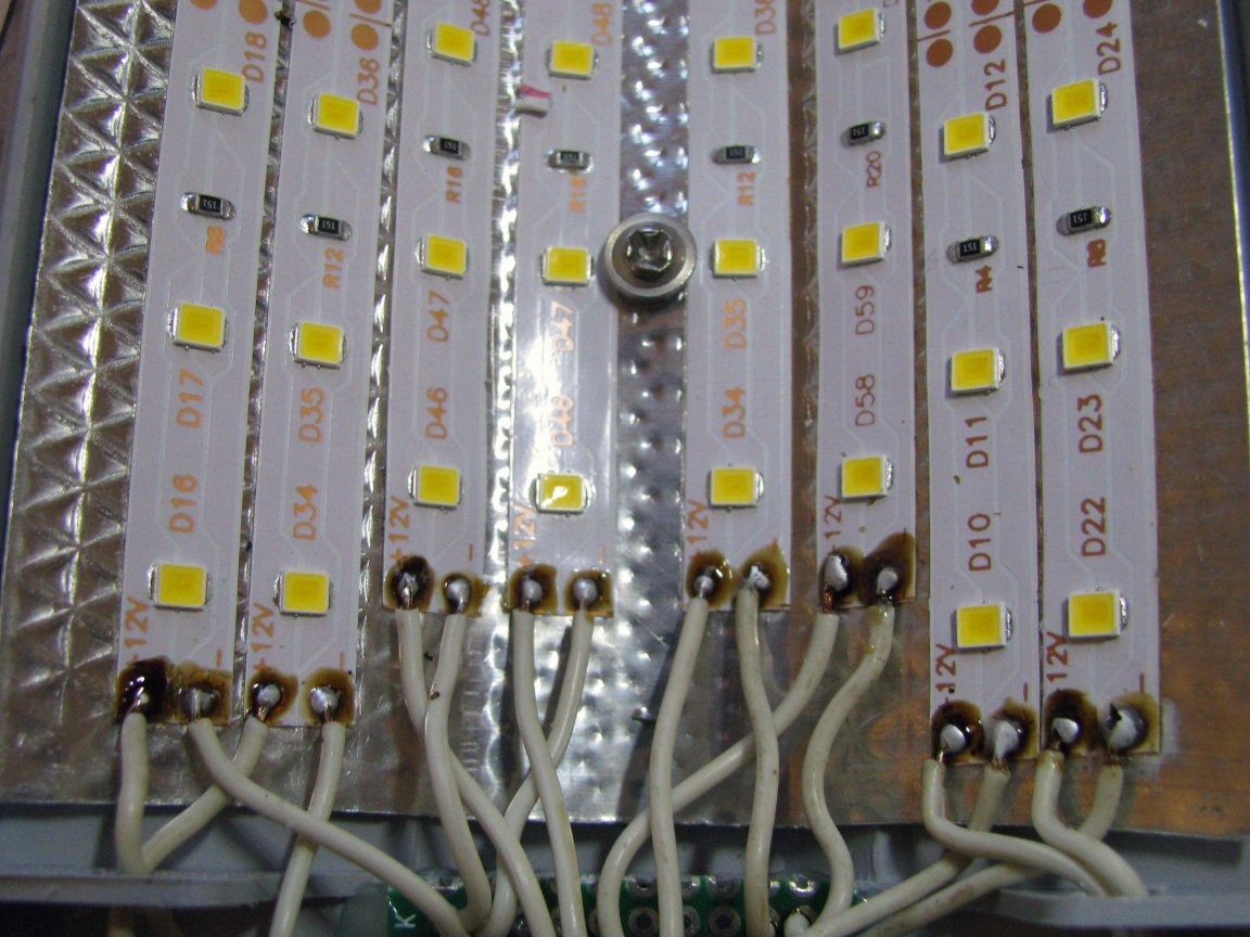
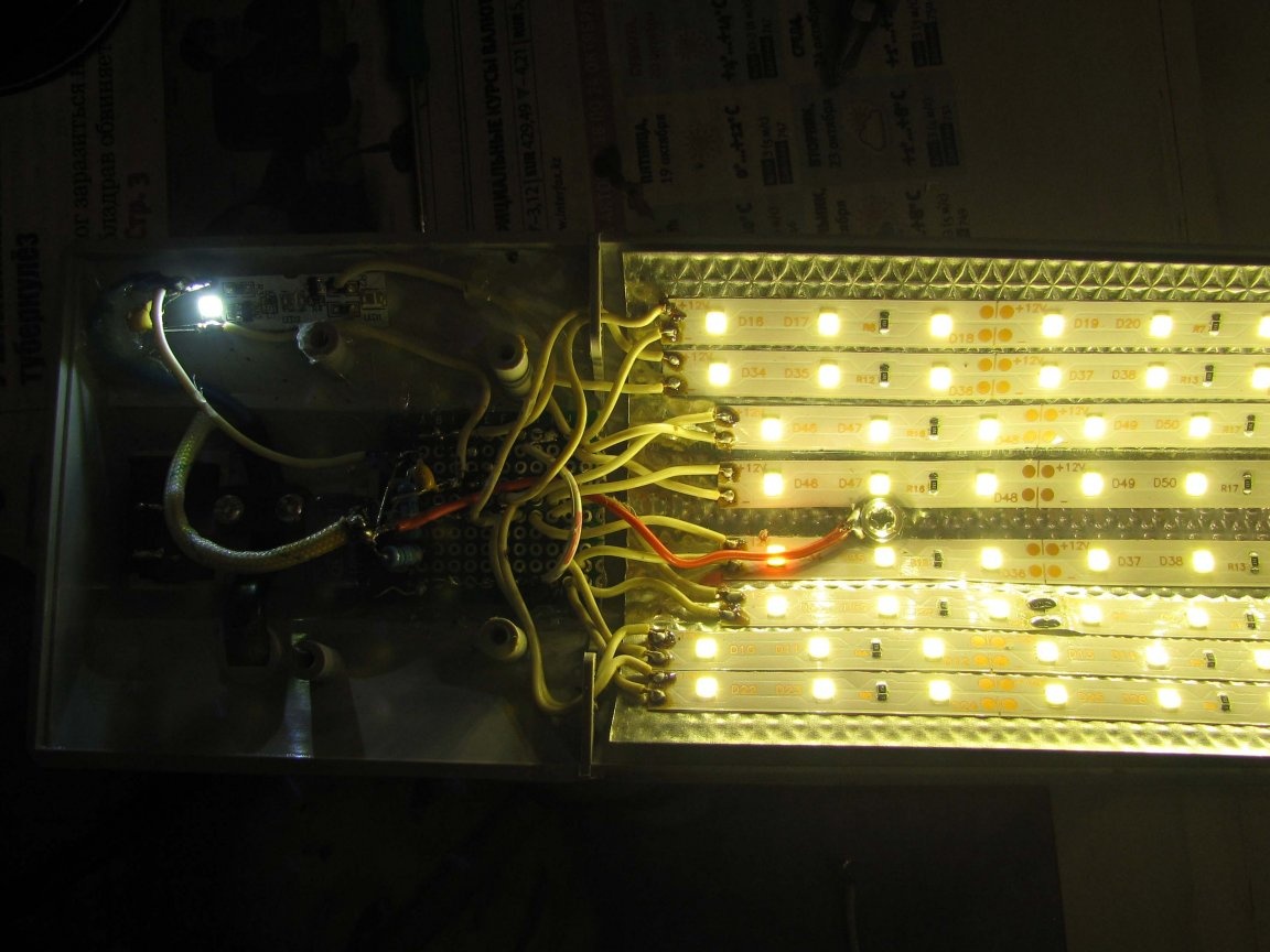
Having cut off a suitable piece of the circuit board, I prepared and irradiated 16 conductors. At the same time, a group of eight conductors was located in the center of the circuit board and was defined as positive conductors, and two groups of four conductors each were intended to be connected to the negative pole of the power source.
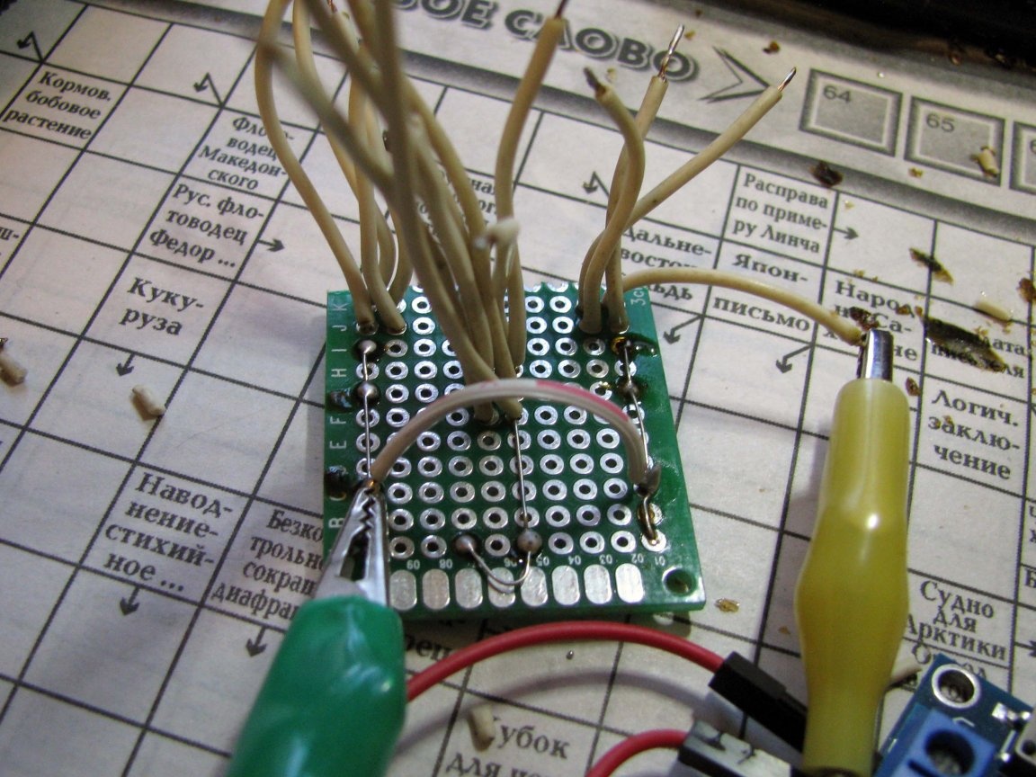
To my joy, it was very easy to solder, and literally after 7 minutes, I already got the finished version.
and
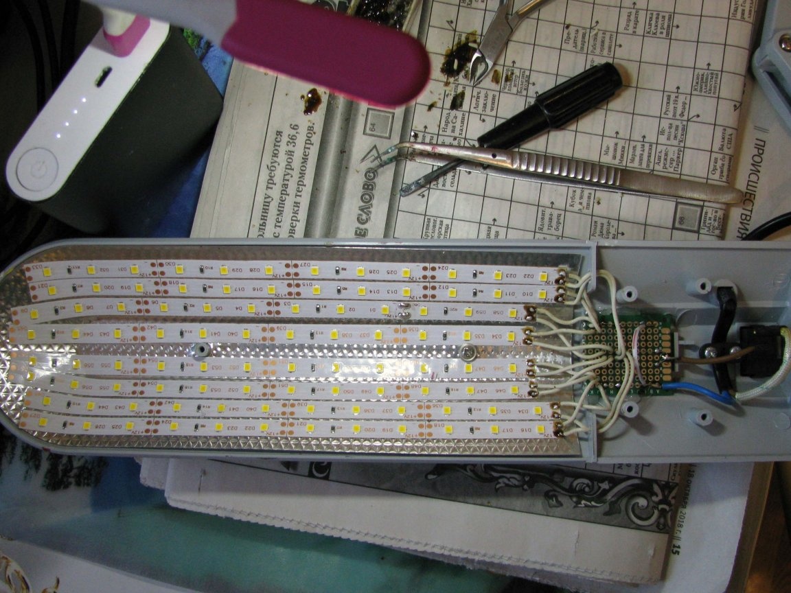
I put the scarf on the hot glue, and checked the operation at a reduced voltage - the result pleased me.
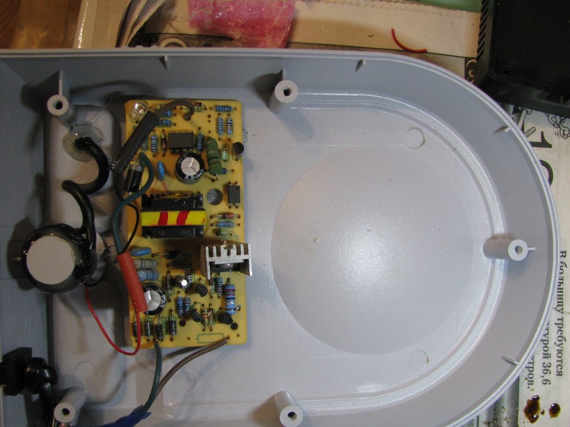
Power supply and stand.
I decided to place it in the stand. Just one such, quite dimensional, I was idle. And again, looking ahead, I will say that - such a placement of the power supply is not the only one.
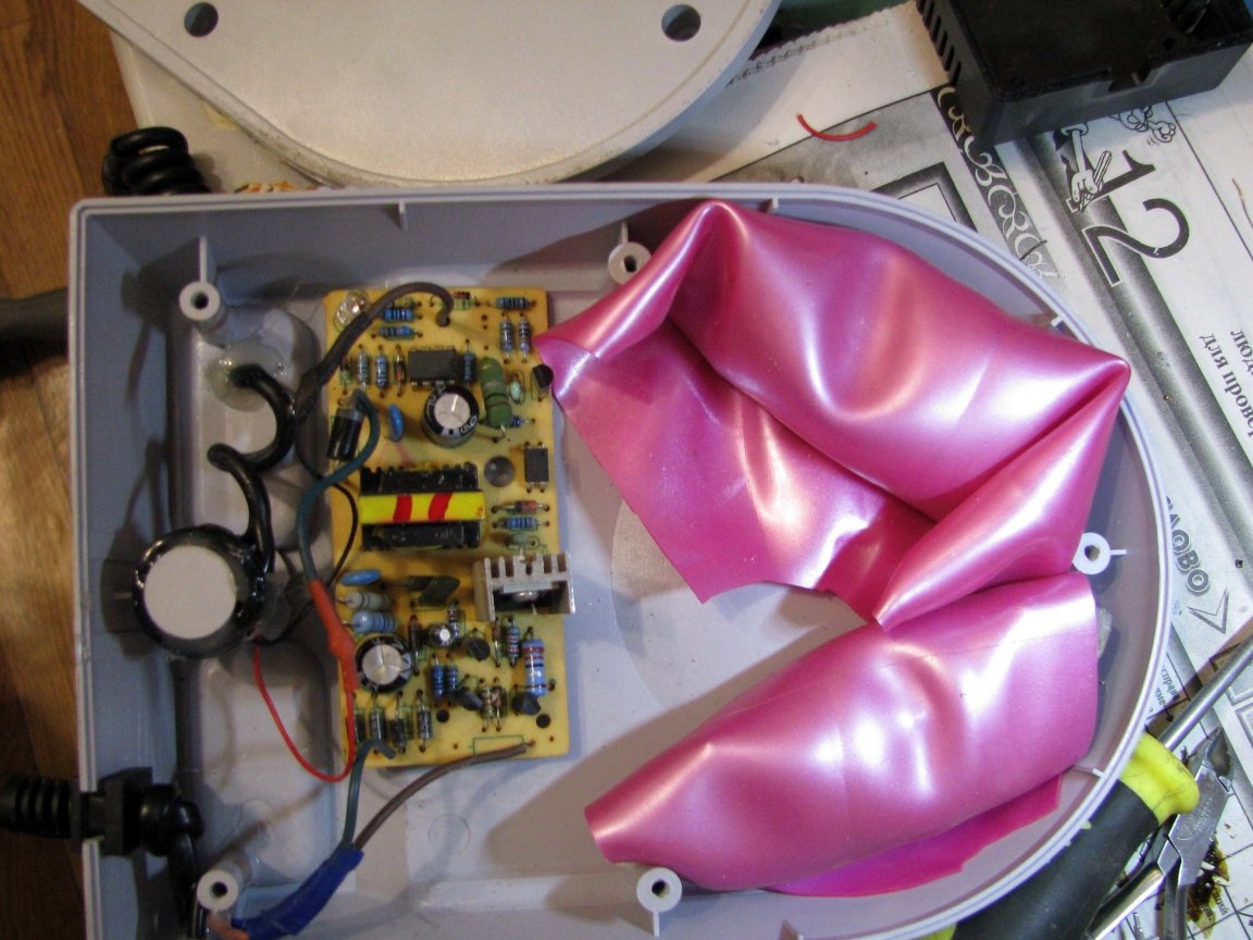
Since I could not accommodate a standard weighting material, I grabbed a plastic bag of sand, but I remembered that six years ago, I was engaged in casting half rings of weighting materials from lead and ran into my magical shed. In the same shed, I came across a punctured rubber ball from my past project.
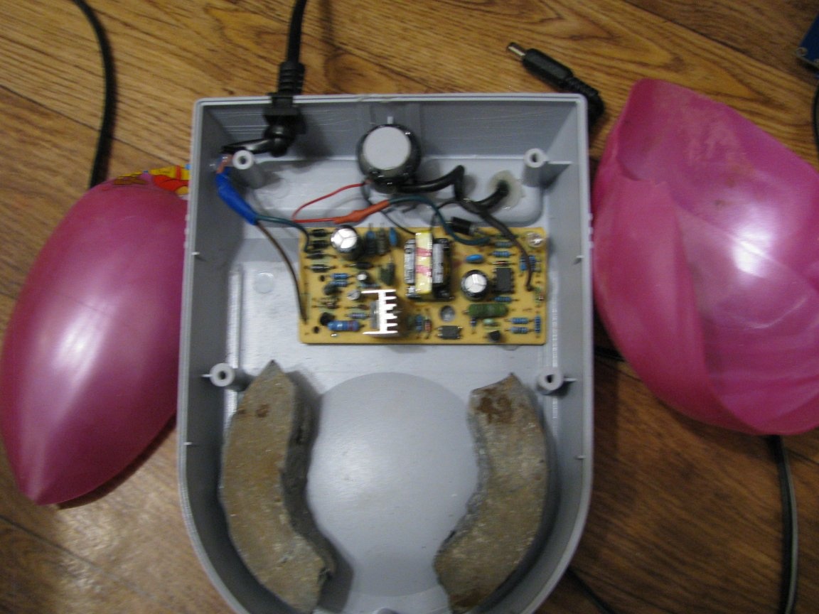
The half rings were flattened on the anvil, since, in height, they interfered with the assembly of the base of the lamp, and were wrapped in halves from a deflated ball - it turned out both tight and elastic.
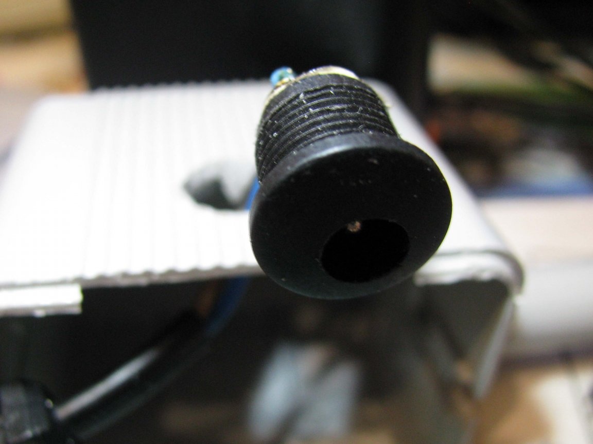
Yes, pay attention to the length of the twisted cord - it was soldered at one end to 12v from the power supply, passed into the hole on the back of the stand. At its other end, a plug was plugged in to connect to the mating socket, which I placed in the empty cubic cavity remaining after removing the throttle.
The general view turned out like this:
Minor repairs.
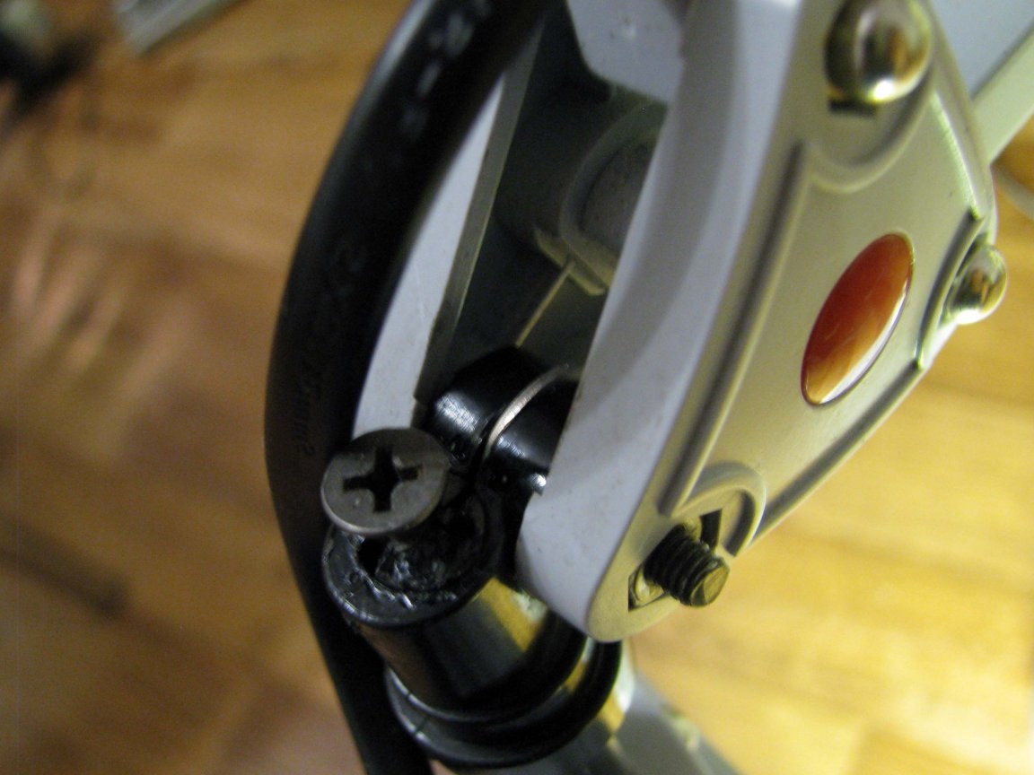
After a year of operation, the head of the lamp with a reflector ceased to be fixed in a horizontal position. In other words, if the head of the lamp was rotated at an angle to the upper link of the lamp foot, the rotary assembly could not withstand the weight of the head, and the head itself fell down.
This, of course, was to blame for the weight of the fluorescent light bulb. And although the weight of the entire lamp assembly has significantly decreased, this problem remains.
It was impossible to disassemble this knot, and I just sawed off the plastic ebbs of the spacer of the knot, and screwed a self-tapping screw between the spring petals.
Everyone who came across such a lamp - faced with this - figure it out =)
Touch control.
Look down at the pictures, you will see the pink USB lamp on a flexible leg, it is touch-sensitive. Such lamps, I scored five pieces a few years ago at fifty cents apiece.
In general, I gave three, and two left. The LEDs in one of them have lost brightness, this is especially noticeable in comparison with the new one.
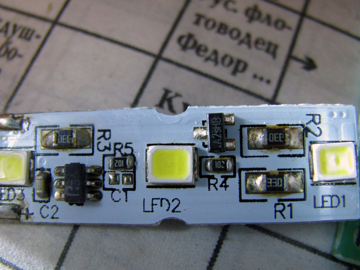
Inside the lamp are hidden:
- TPP223 chip;
- field P channel transistor SI2301;
- three LEDs;
- and SMD strapping all of this.
As you know, this is a ready-made management scheme, and I couldn’t flatter it.
I, as I could, tried to draw the final outline correctly, I hope Ivan_Pokhmelev, will take a look and correct me if I messed up something. =)
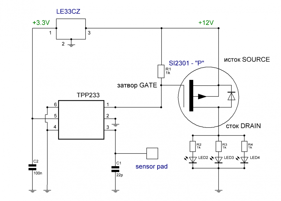
The only thing is that on TPP223 I applied with a 3.3v integral stabilizer. I pulled two LEDs off the board, and left one extreme for debugging.
Well, the result:
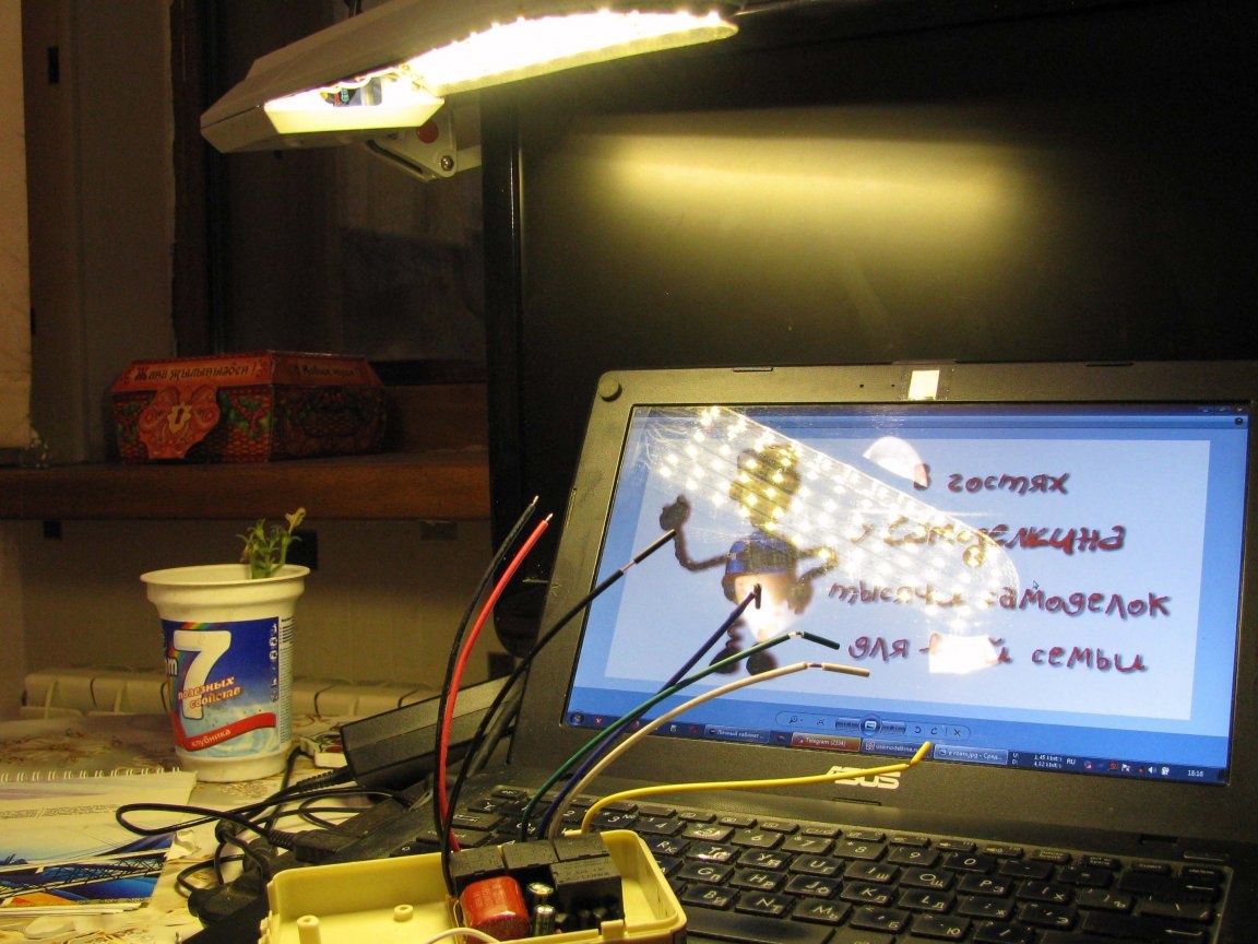
The total current was around 0.85A.
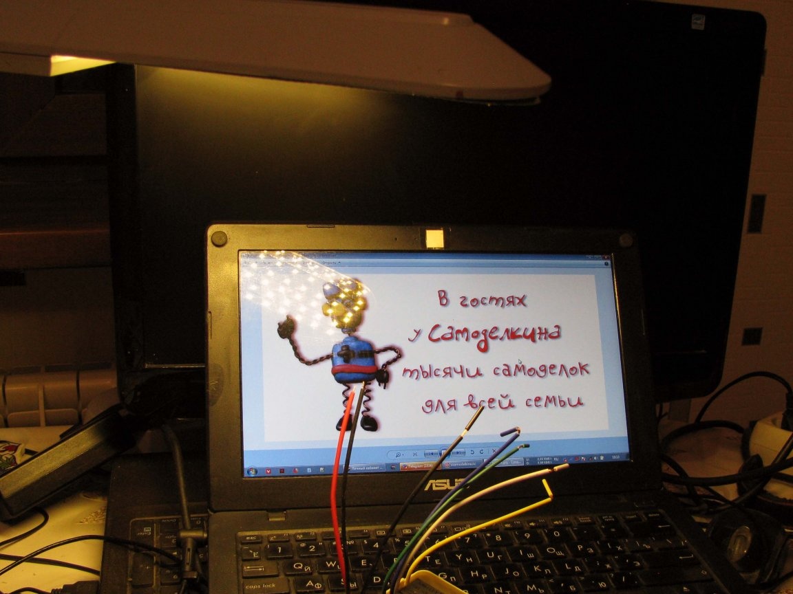
In the background you see a monitor inside which I have built-in UMZCH and I will release a separate article about it, and on a small laptop, you can see an almost completed project of a “nashkafnaya” radio-controlled LED backlight, - I almost finished it, and the other day, publish as well =)
What could be done differently.
I, as you can see, used a dimensional power supply - but it really was.
You also saw that the cubic cavity in which the throttle was located remained empty. If you have a small-sized 12v power supply at hand, it is better to place it there. Then, in the stand, you can place the wireless charging coils, they are just asking for it, and for the detachable connection of the stand and the power supply, you can use the same technique that I used =)
References:
- .