
Greetings the inhabitants of our site!
After taking measurements of sound amplifiers on TPA3116 microcircuits, the author of YouTube channel “Radio-Lab” noticed that some amplifiers do not play at full power when connected, for example, to a phone or bluetooth module, this can be seen from measurements.
This also applies to other amplifiers. This is due to the fact that some amplifiers have a low input sensitivity. As a result, a phone or a mortise module simply cannot swing such amplifiers having an insufficiently powerful output signal level. If you need to swing the amplifier to the full, as an option use pre-amplifiers or abbreviated preamplifiers. The preamplifier increases the level of the audio signal from the source and then the amplified signal goes to the main amplifier, and the main sound amplifier can already play at full strength. The principle of operation is very similar to a hearing aid, but for an amplifier.
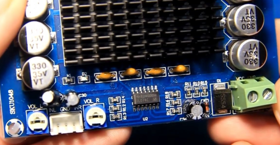
On some models of amplifiers there is no such problem, the board already has a built-in preamplifier from the factory or is not needed at all.
If you are sure that the amplifier plays quietly precisely because the input signal is weak, then the preamplifier can be purchased or assembled as a separate board and connected by wires to the main sound amplifier.
This article will discuss how to independently do it yourself assemble the preamplifier. A unipolar circuit has been found on the Internet, although there are many different ones.
The characteristics are as follows:
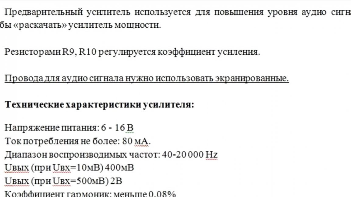
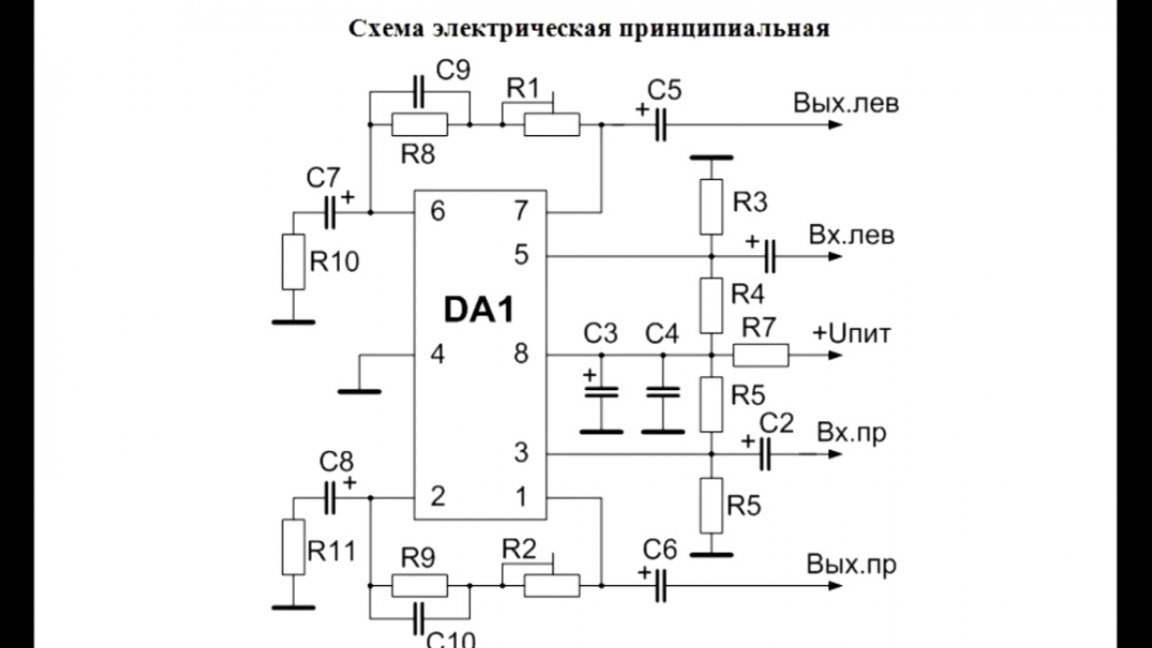
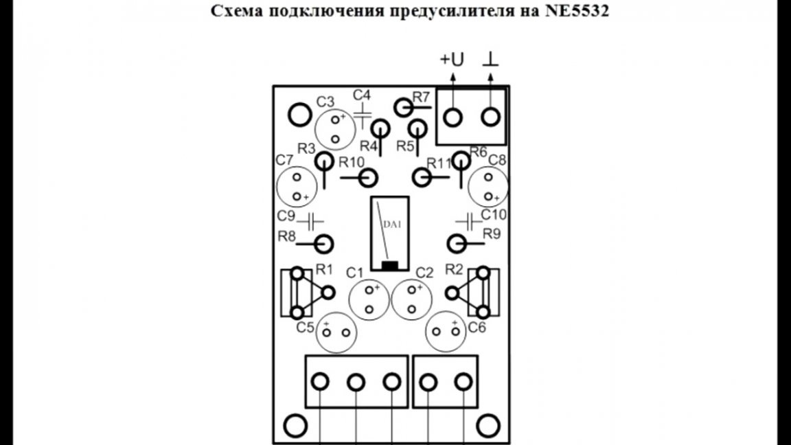
The connection diagram is as follows:
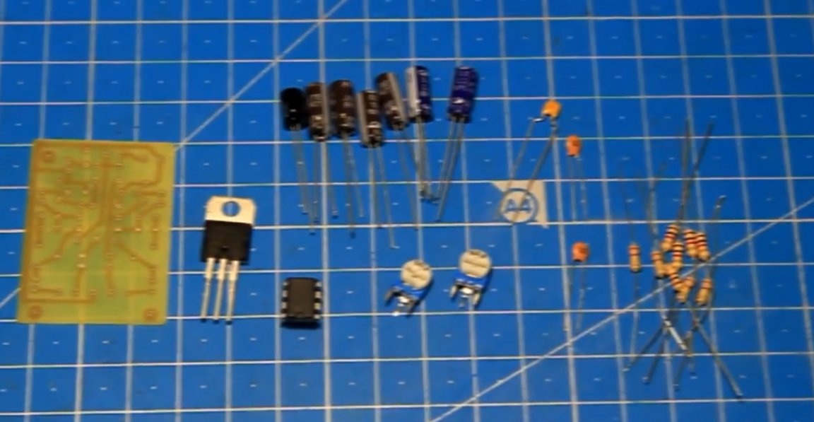
Necessary Details:

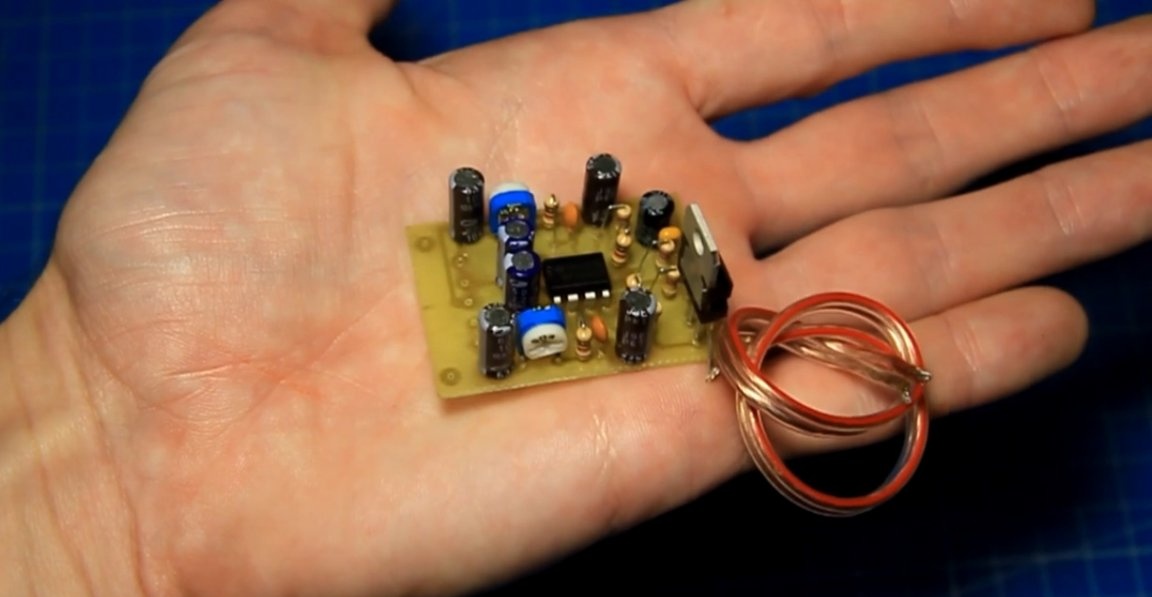
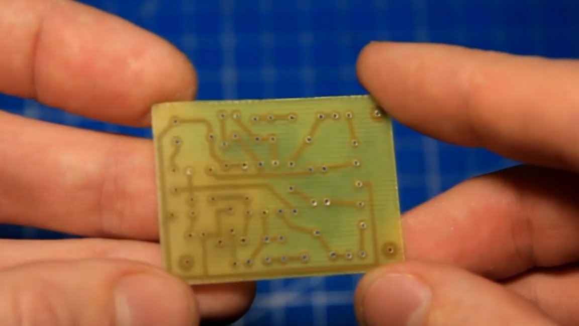
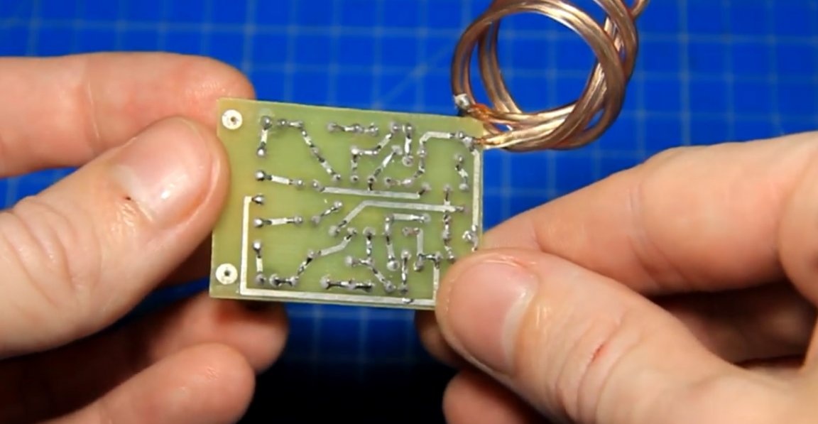
For this project, the author made a printed circuit board. The board was compact, just right for the future preamplifier.
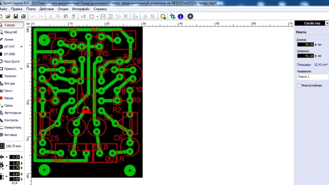
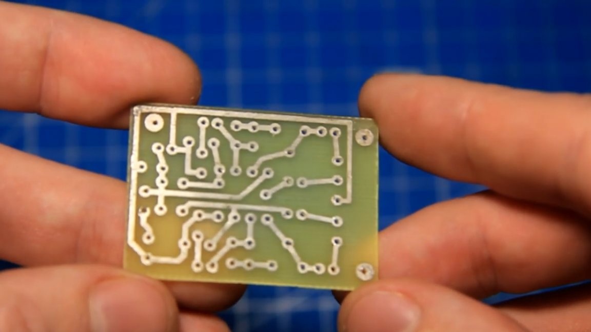
The necessary radio components were bought on the radio market (you can order from China, but there they are mainly sold in bundles, and it takes quite a while to wait).
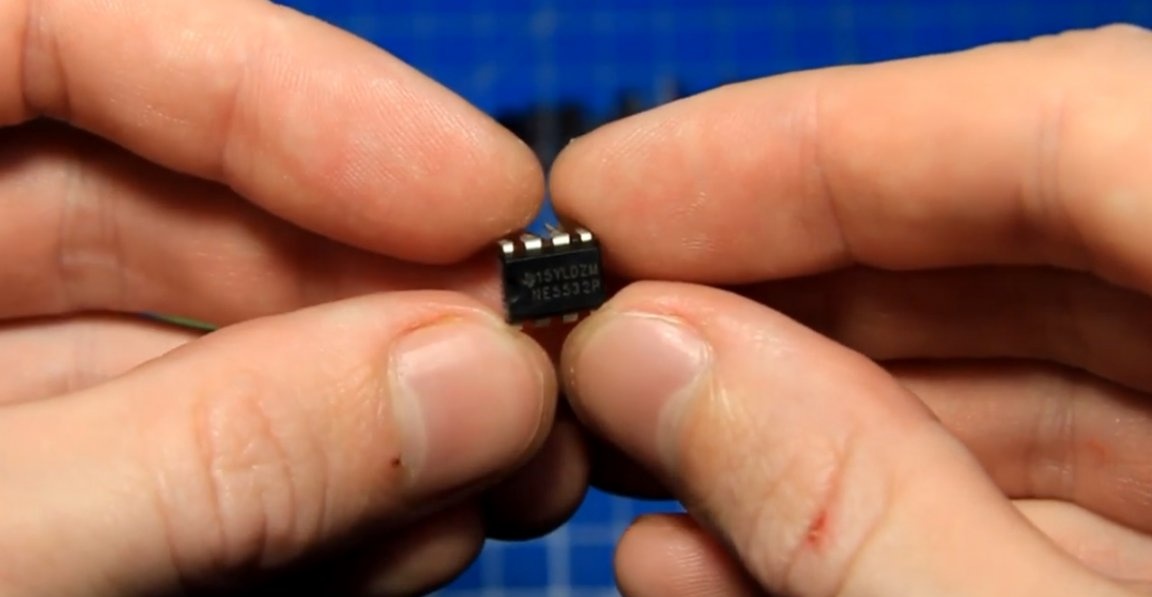
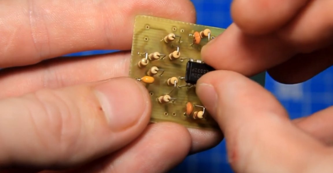
For amplification will meet the popular dual operational amplifier NE5532.
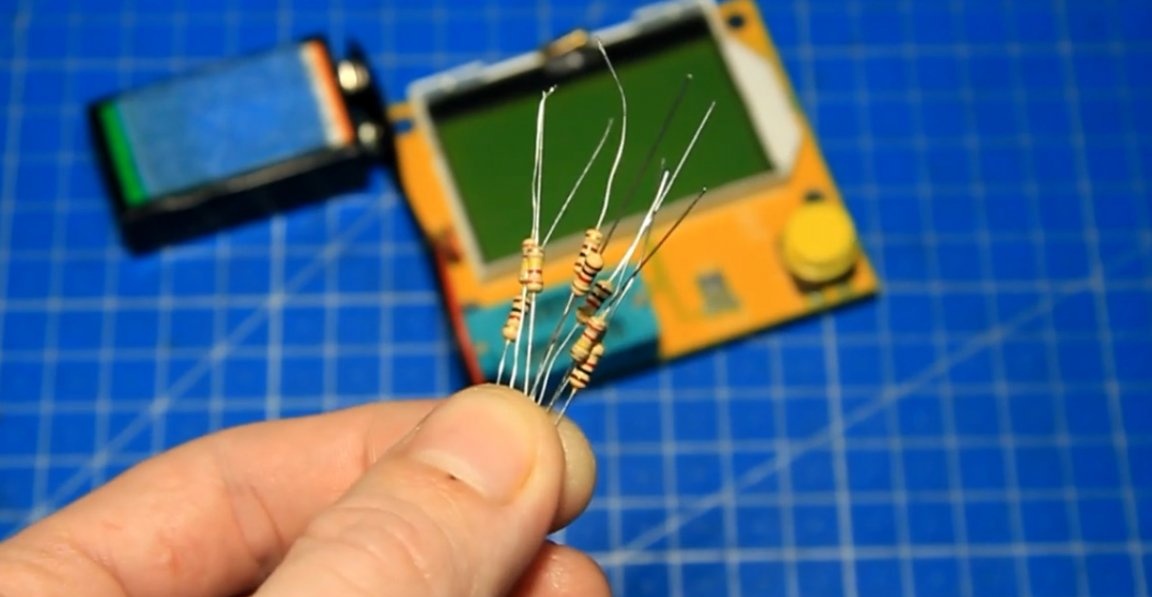
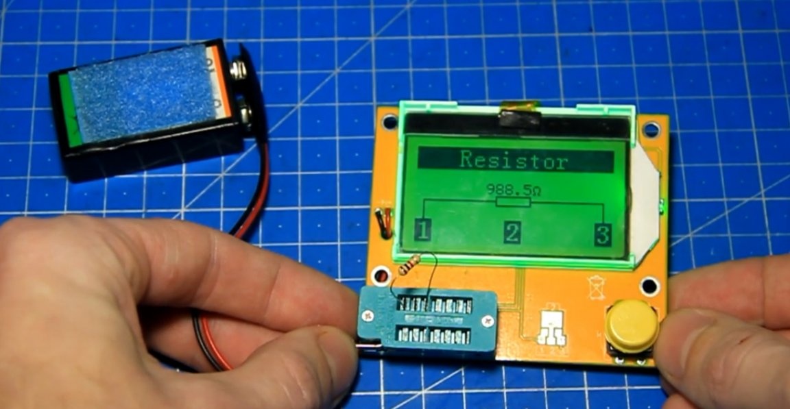
The author decided to start the assembly with the installation of permanent resistors. In order not to mess with the ratings, he uses a radio parts tester. To do this, it is necessary to install a resistor in the tester and after literally a second the tester showed a nominal value of 1 kOhm.
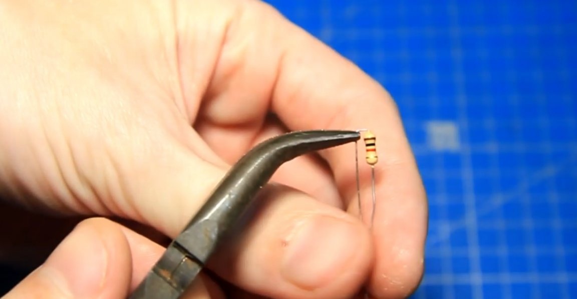
We bend the resistor legs so that the part is installed vertically.
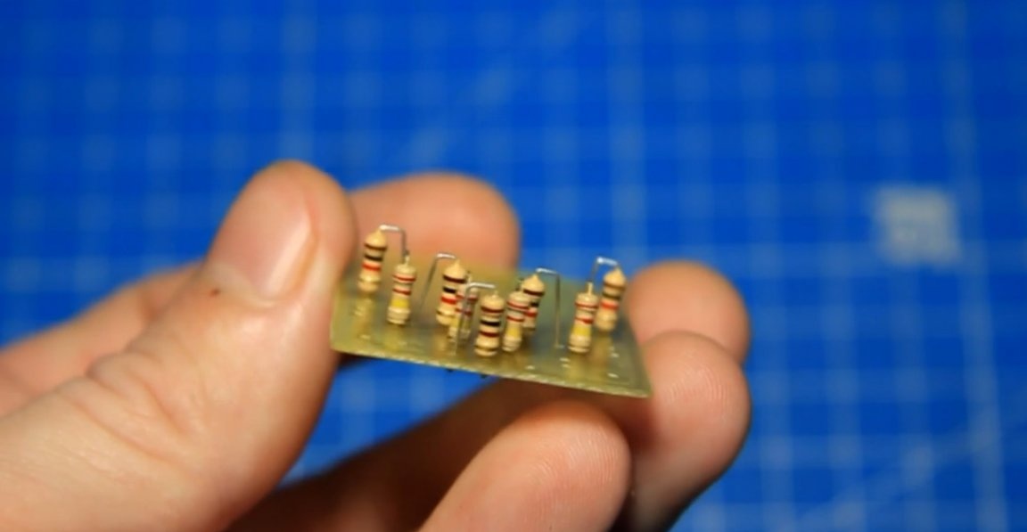
Then we put the resistor in its place and fix it with a soldering iron. Next, solder the second leg and then solder the remaining 3 resistors with a nominal value of 1 kOhm into place. After that, we solder 4 resistors of 220 kOhm and one per 100 kOhm.
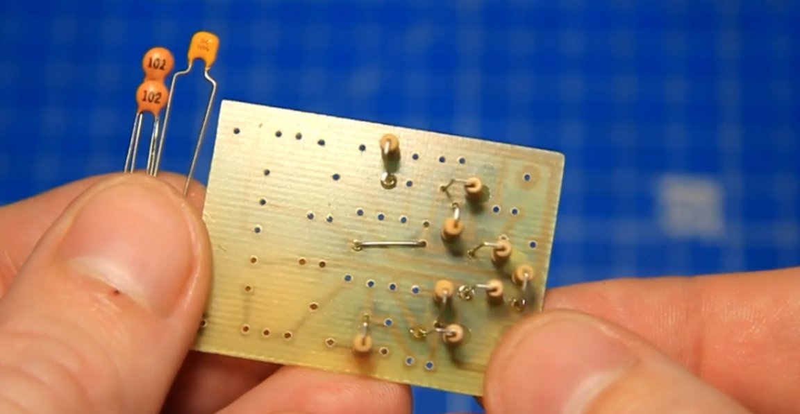
From the scraps of legs we make a jumper and put it in its place. Next, we replace the capacitors, multilayer and disk. We set the chip by the key.
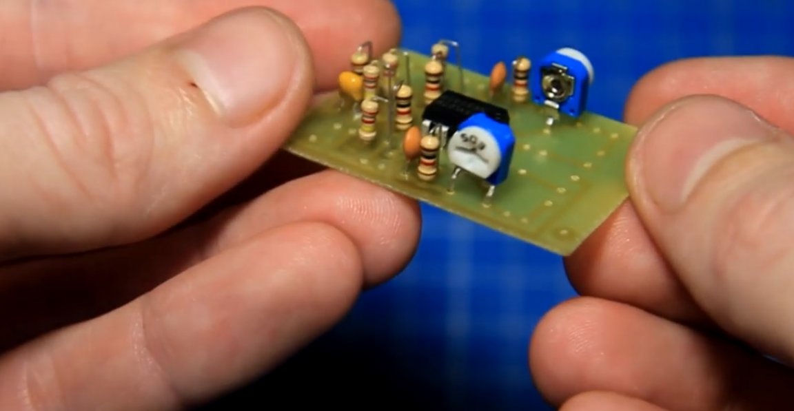
Trimmer resistors 2, each on its own channel, their places on the sides of the board.
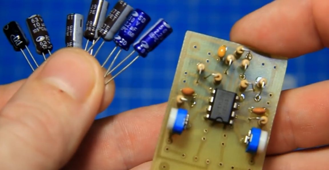
Electrolytic capacitors must be installed with the correct polarity. We install them on the board in accordance with the scheme.
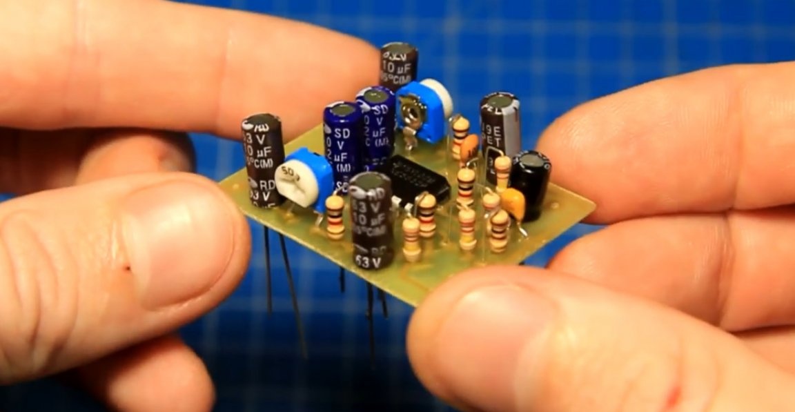
And now, all the necessary details are installed. We can say that the preamplifier is assembled.
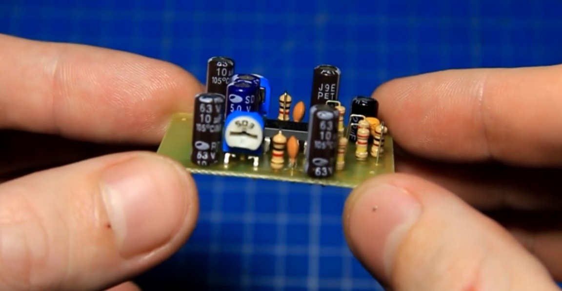
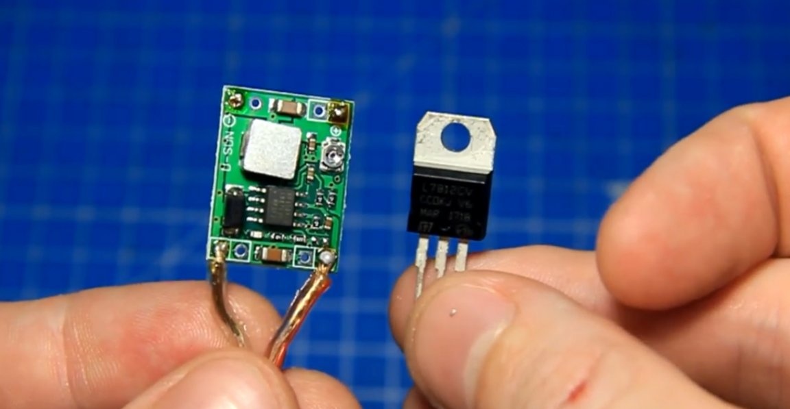
The supply voltage is from 6 to 16V, but in this case, the author plans to supply it with a voltage of 24V, as well as an amplifier. This is already a lot for the preamplifier and you need to use a step-down stabilizer. When powered by a pulse converter, there were noises, because the author decided to use a linear stabilizer on 12V L7812.
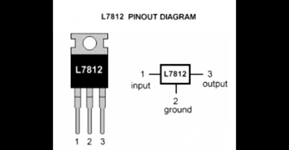
In accordance with the pinout, we solder the stabilizer onto the board, and also solder the power wires.
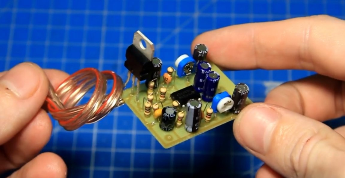
The preamp is now assembled. This is such a small fee.
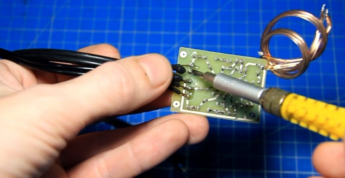
Stereo board, on 2 channels. To test the inputs and outputs, solder the shielded wires so that there is no interference. In the middle is a common wire, near the sides of the entrances and closer to the edges of the exits.
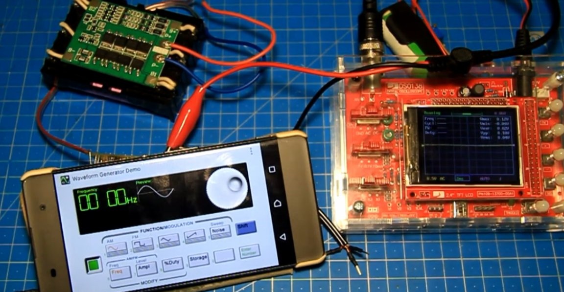
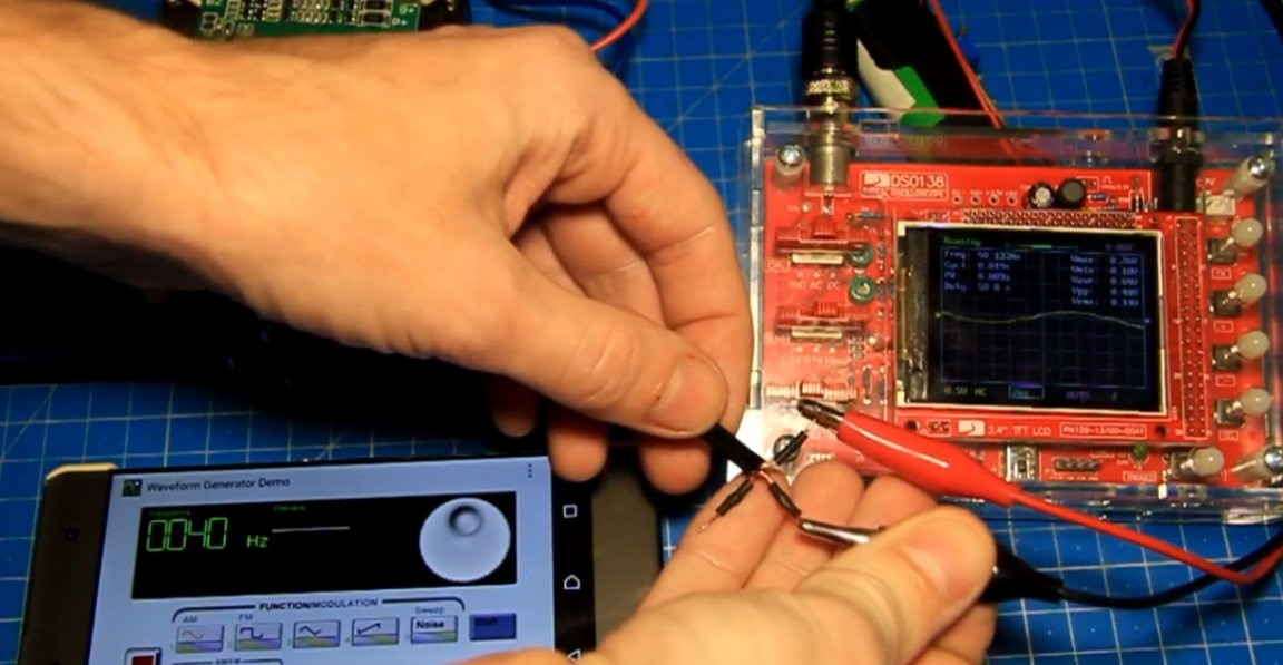
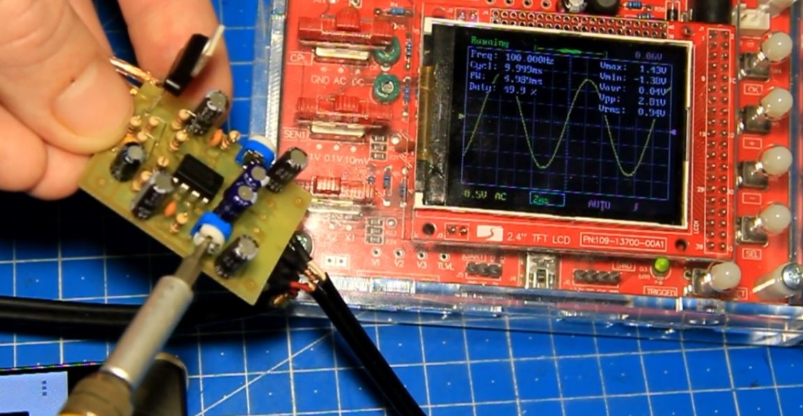
To check, the author powered the amplifier from the battery, and the signal will be visible on the oscilloscope. The source of the sine wave will be the telephone. We connect the oscilloscope to the phone output first. The maximum output signal from the phone was approximately 0.5V. Here's a picture at maximum volume.
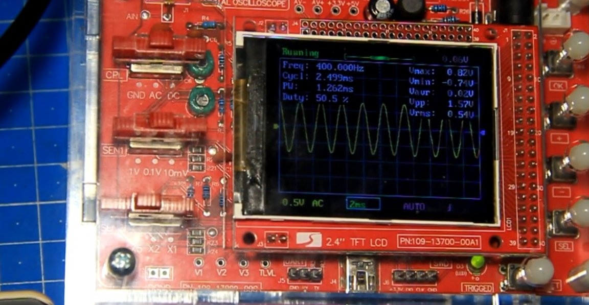
Now connect the oscilloscope to the preamp output. The preamplifier is powered and we check its performance. We raise the volume under its sines and you can see that there is also a sine at the output and its level is several times higher than it was from the phone. This is already about 2V.
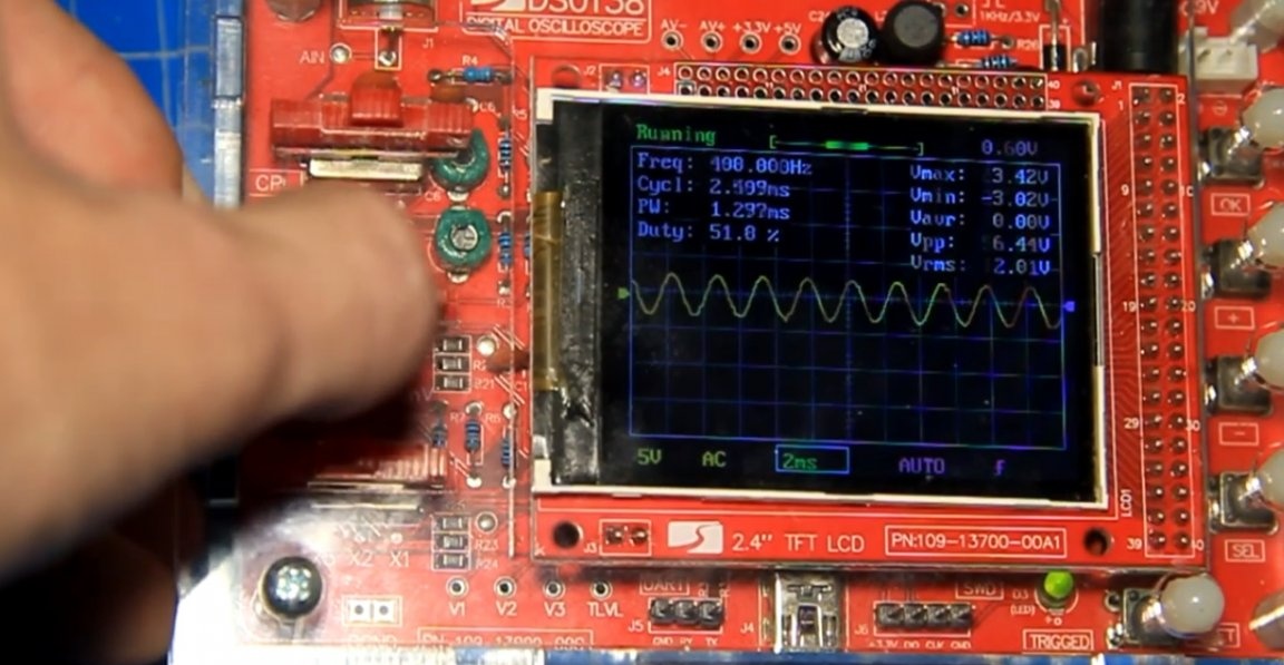
It can already be said that the assembled pre-amplifier works and amplifies. If there is a lot of input signal, that is, clipping.
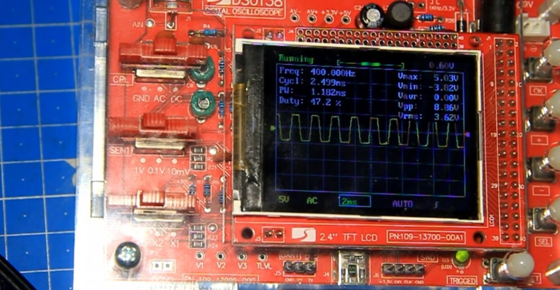
Then we connect to the second channel.
And here, too, there is a sinusoid. Also try changing the frequency. Everything works, there are two level adjustments on the board, which allows you to adjust the necessary gain level.
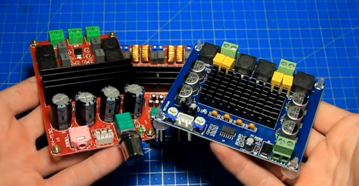
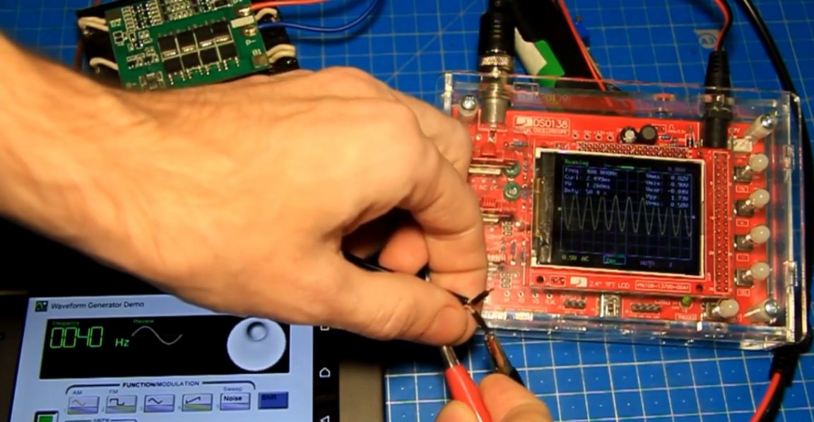
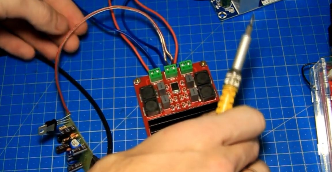
The sine wave itself without distortion, according to the preliminary amplifier, everything is fine. Now let's try connecting it to an amplifier. As a test author, I took an amplifier on 2 TPA3116 microcircuits and a 24 volt power supply for it.
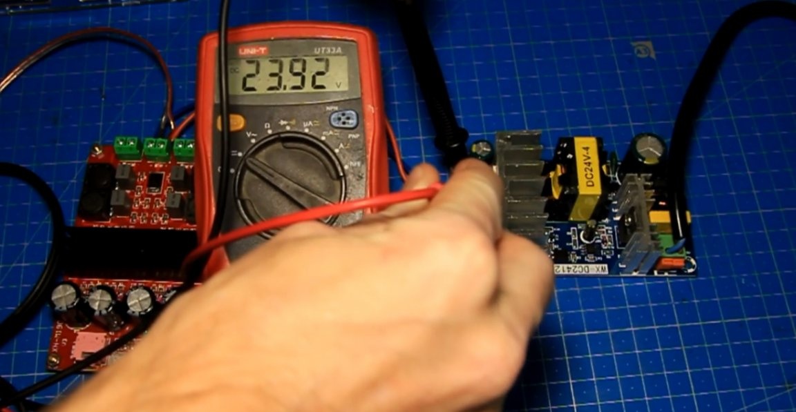
The output is almost 24V. The load will be such a 4 Ohm wire resistor.
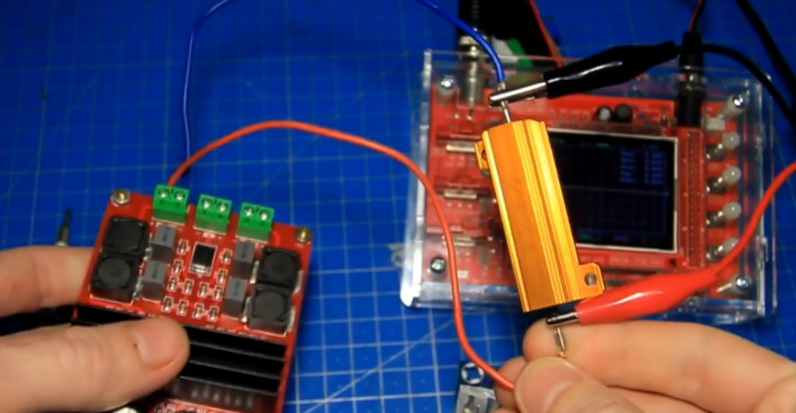
An oscilloscope is connected to it to see the waveform at the output of the amplifier. To show the difference, we first apply a signal directly from the phone, then we turn up the volume and the voltage at the output of the amplifier turned out to be about 10V.
In terms of power, it is approximately 25W. That's the power this phone can swing this amplifier with a load of 4 Ohms. And now everything is the same, but with a pre-amplifier connected between the phone and the amplifier. We connect and raise the volume.
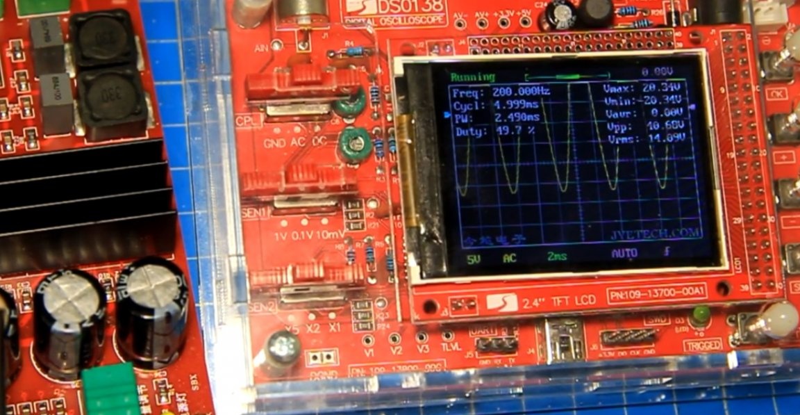
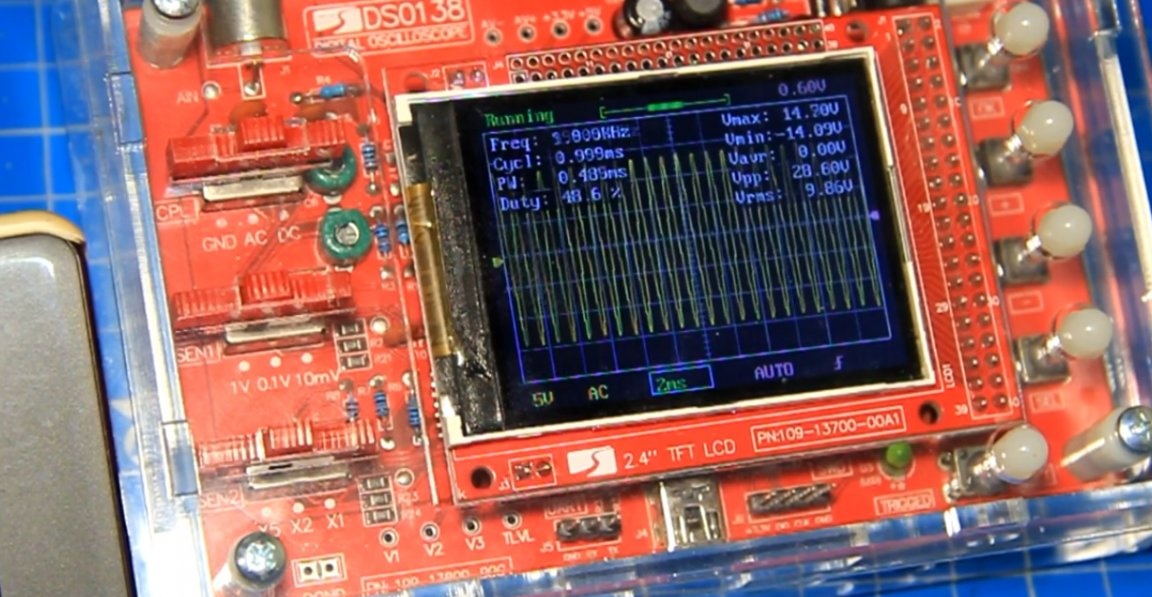
You can see that now the signal at the output of the amplifier is already higher, and this is approximately 14.5V. In terms of power, it is approximately 53W, which is already twice as high as it was. If you raise the volume strongly, then clipping is already observed.
All calculations are approximate, but I think the essence is clear. Now this TPA3116 amplifier paired with a preamplifier can give maximum power. And also the preamp can be powered directly from the amplifier. To do this, observing the polarity, connect the power wires of the preamplifier in parallel to the power wires of the amplifier.
The lowering stabilizer is barely warm. Powered up, now raise the volume.
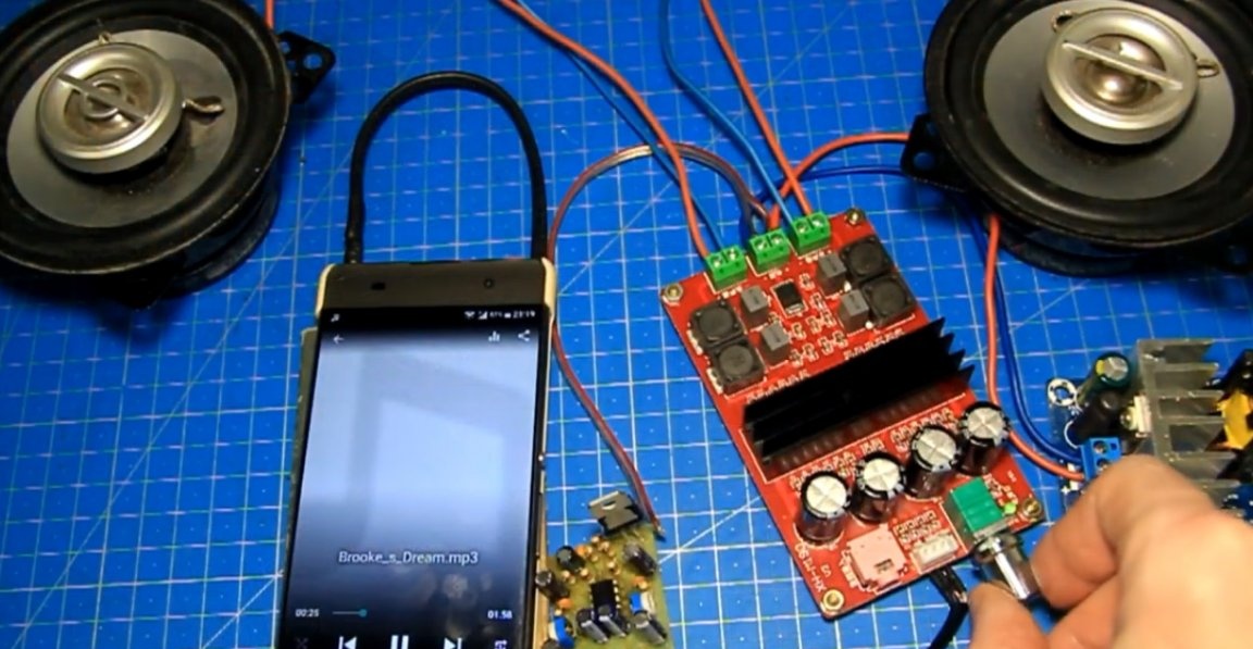
All the same, only from one power supply. No extraneous noise, all is well. The assembled preamplifier works perfectly. It can be used with other amplifiers, TPA3116 was taken by the author as an example. If the input sensitivity of the amplifier is insufficient, then one of the solutions may be to install a pre-amplifier.But again, you need to understand that maybe your amplifier is weak and installing a preamp in this case will not solve the problem, you just drive your amplifier into a clipping, there will simply be big distortions and that’s it. And so it works, you can collect and repeat. The board is universal and suitable for many sound amplifiers. This pre-amplifier is one of many, there are others. Useful links will be in the description under the author’s video (link SOURCE).
Thank you for attention. See you soon!
Video: