

An interesting film on TV is often shown late in the evening or at night. At the same time, someone wants to see him, but someone went to sleep. Therefore, in order not to interfere with sleeping, you have to look for a way out.
The easiest way is to listen to the sound of TV shows through wired headphones, but the connecting wires create inconvenience.
For wireless listening, you can use the transmitter-receiver communication system. Sound transmission can be carried out due to inductive coupling or in the infrared range, but these are already obsolete and inefficient methods.
Of the more modern methods, this is the use of bluetooth sound transmission modules - a transmitter (transmitter) and a receiver. This is a sound transmission with good quality (if you are lucky with the purchase), but only at a distance of several meters. In addition, the kit will cost a lot, and finding a bluetooth transmitter in the city’s stores is very difficult. Therefore, this option is only suitable for fans of Chinese shopping.
At present, the method of wireless sound transmission operating on radio frequencies in the VHF range is also widely used. Most often this can be found in automobile transmitters, which are now sold in almost every kiosk. A transmitter operating on this principle has a simple circuit on common components and, depending on the power, provides communication with the receiver at a distance of up to a kilometer.
For these reasons, it was decided to manufacture do it yourself Transmitter (transmitter) operating in the VHF FM band 88-108 MHz.
The radio transmitter is designed for wireless transmission of sound accompaniment of television broadcasts or computer broadcasting. Its main task is to transmit sound over the air within the apartment.
The signal from this radio transmitter can be received on a small-sized VHF FM radio receiver, on the receiver in a mobile phone or wireless headphones with an VHF FM radio receiver.
The radio transmitter is connected to the TV through the headphone jack. Since any modern TV (or digital set-top box to TV) has a USB connector, then to exclude worries about batteries, we use power for the transmitter (+5 v) from this connector.
Transmitter circuit
The initial data for the manufacture of the transmitter have been determined, go to the device diagram.
After analyzing the manufactured designs of radio transmitters on the Internet, a device was formed according to the following scheme:
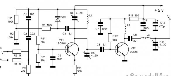
A two-stage radio transmitter scheme was chosen, where both blocks are clearly expressed and each transistor has its own role. In this design, each stage of the device can be easily configured individually.
Circuit description
The scheme is simple and can actually be assembled from improvised components, the ratings of the components used are indicated on the scheme.
The device consists of a high-frequency (HF) master oscillator on the transistor VT1, a frequency modulator on the varicap VD1 and an RF amplifier on the transistor VT2.
The HF generator operates at the resonant frequency of the oscillatory circuit L1, C4. Capacitor C4 sets the required frequency. Capacitor C5 is used to configure stable generation.
The stereo audio signal from the TV AUDIO line output is fed to the transmitter stereo sound adder on resistors R3 and R4. The signal is summed on the resistor R5 and fed through the isolation capacitor C2 to the varicap VD1.
The carrier frequency of the transmitter is modulated by the VD1 varicap. When a sound signal arrives, an alternating voltage appears on the varicap, which changes its capacity in time with the sound to a small extent, with frequency modulation of the VHF signal. To set the working area of the varicap, a constant voltage is supplied to it through resistor R8 from the divider to resistors R1 and R2, the value of which is adjusted by selecting resistor R1.
Separating capacitor C8 connects the generator to the RF signal amplifier, built according to a typical circuit. Elements L3, C10 are designed to coordinate the output of the amplifier with the antenna and increase the stability of the device.
The transmitter is powered by the USB port of the signal source, voltage 5 V and consumes a current of not more than 30 mA.
Manufacture
1. Details
Two imported high-frequency transistors BC548 are used in the radio transmitter. Although, these are not exactly high-frequency transistors (maximum operating frequency up to 300 MHz), but they provide good work in the circuit. Transistors can be replaced with any high-frequency ones, with a cut-off frequency of at least 500 MHz and the maximum possible gain.
Varicap VD1 according to the scheme - KB102. You can use other varicaps KB109A, KB122A, KB132.
When assembling, you can use any small capacitors and resistors. They can easily be found in old boards from unnecessary radio equipment.
2. Production of coils
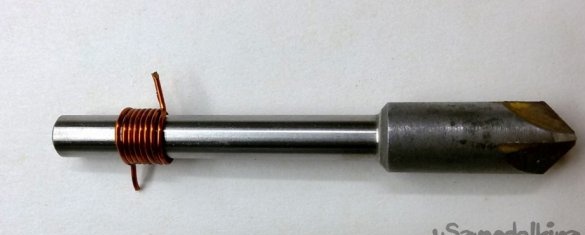
All inductors are frameless, wound on a mandrel with a diameter of 6 mm enameled wire PEV-2 with a diameter of 0.7 mm. Coils L1 and L3 contain 7 turns, coil L2 - 15 turns.
We wind the coils tightly, turn to turn, using a screwdriver.
Cut off, with a margin, the desired wire length for one or more coils. We clamp a mandrel with a diameter of 6 mm in the cartridge (in this case, the diameter of the countersink shank) and simultaneously clamp the end of the cut wire. We turn on the screwdriver and wind the entire wire onto the mandrel, while braking the free end of the wire to create uniform tension. A slight compression of the wire by hand, between two wooden battens, allows you to create tension during winding and straighten the wire, while maintaining the insulation varnish. Remove the wound coil and cut off the desired number of turns from it. We bend the ends of the coil for its installation in the board, we clean and tin them.
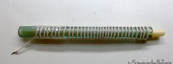
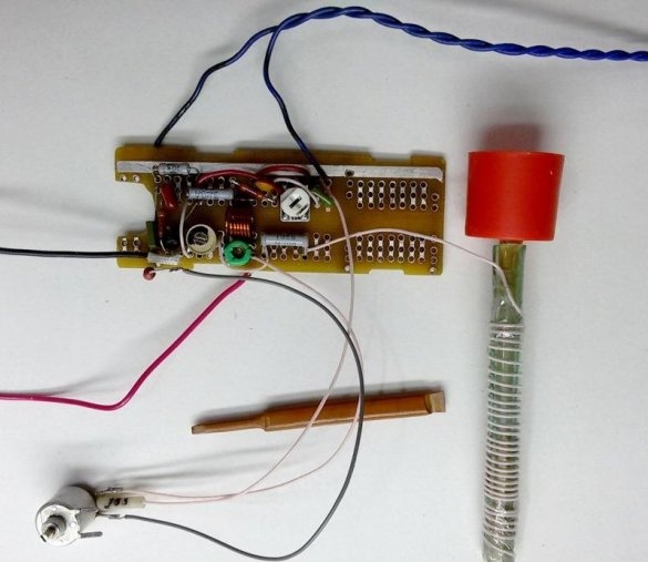
3. Antenna fabrication
The antenna is made of stranded wire with a diameter of 0.5-1 mm. The length of the antenna should be equal to a quarter of the wavelength. For a frequency of 88 MHz, the optimal antenna length should be 0.85 m. To reduce the size, it can be rolled into a spiral. This can be done on a piece of antenna cable with a length of 80 ... 90 mm, having previously removed the central core and the braid from it. Or take as a basis a suitable-sized tube. We evenly distribute the turns along the length and fix them with tape. After positive tests of the device, we arrange the antenna with a heat shrink tube.
4. Fabrication of the circuit board
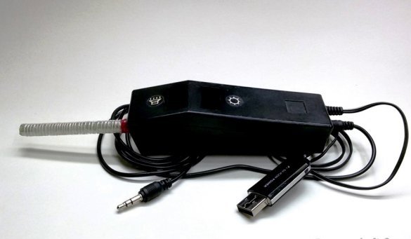
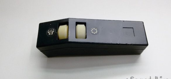
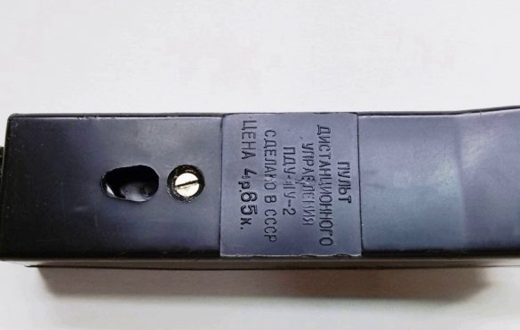
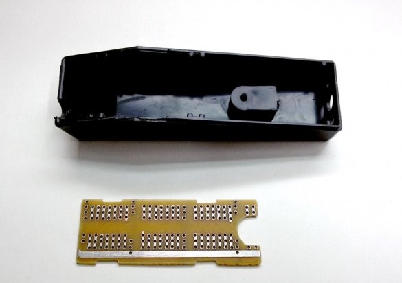
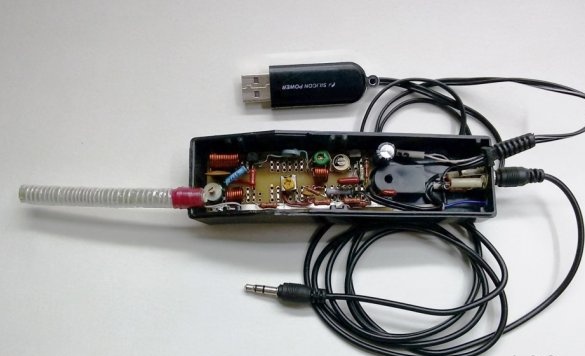
To mount the parts of the device we will manufacture a circuit board.But to determine its size, you must first select the device body. In this case, the case was used from one of the first wired remote controls for the TV.
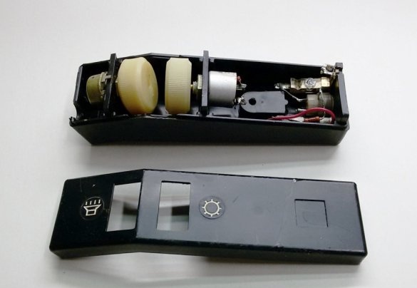
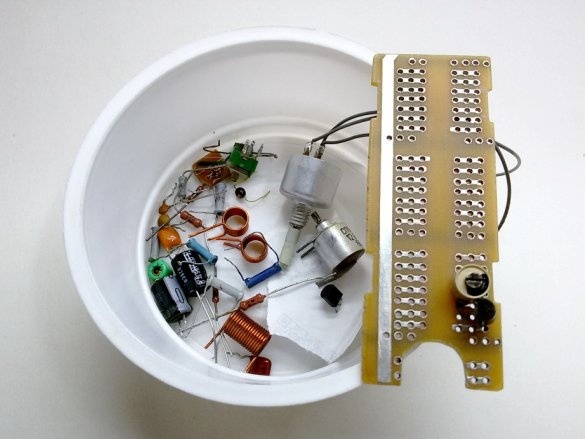
Having freed the case from the contents, according to its internal dimensions, from the universal board we cut out the circuit board for the device. We clean and service the tracks.
5. High frequency generator
On the prepared circuit board, we perform the installation of the parts of the HF generator on the transistor VT1 and the frequency modulator on the varicap VD1. In the entire structure, during installation, in order to reduce mutual interference at a high frequency, it is necessary to exclude the intersection of conductors as much as possible and to perform installation with minimally short conductors.
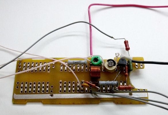
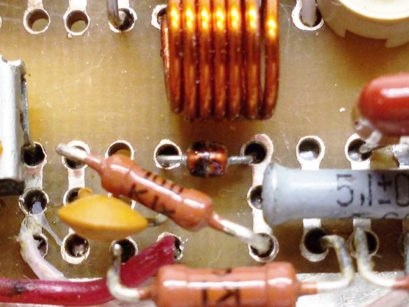
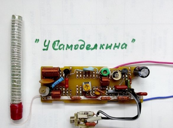
In the modulator, you can apply other varicaps. An imported varicap of an unknown breed was used in the manufactured device (in the center of the photo, under the coil). When measured, he showed a capacitance of 90 pF. After adjusting the work area, the varicap works fine in the circuit.
To adjust the parameters of the circuit, instead of the adjustment resistors R1 and R6, we set, for the time of debugging the circuit, tuning or variable resistances of close nominal value.
We connect the antenna to the capacitor C8. Through the isolation capacitor C2 we connect the sound source, for example, from the headphone jack of a portable receiver.
We connect the board to a 5 volt power source. It should be noted that the power supply of the circuit must be stabilized, from a source with a low level of ripple.
6. Setup
Using resistor R6, we set the bias voltage on the basis of transistor VT1. For a silicon transistor, it should be in the range of 0.6 ... 0.7 volts.
If the installation was made without errors, in compliance with the elementary rules of the RF installation and serviceable parts were used, then setting up the device is reduced to setting the circuit to a free range in your area so that other stations do not drown out the useful signal. The adjustment is made by changing the parameters of the circuit with the control of the quality of reception by ear. The volume level of the signal source is selected so that the modulation depth is sufficient, but does not cause distortion.
Receiving a signal and setting up the transmitter is easiest to do using a smartphone’s digital radio. We place it close to the antenna and set the frequency of reception in the VHF FM band (88-108 MHz) to a frequency free from radio stations. It is advisable to tune the receiver to a frequency of 88 MHz, which is dedicated specifically for such devices.
We adjust the transmitter to the set frequency by changing the capacitance of the tuning capacitor C4. With a plastic screwdriver, we smoothly turn the condenser engine until the characteristic noise disappears in the headphones of the receiver, and when you connect a sound source to the transmitter and this sound appears in the receiver.
If the capacitor fails to tune to the desired frequency, then you can try to stretch or compress the turns of the L1 coil. The frequency of the transmitter will change slightly and tune again with the capacitor C4.
By tuning the capacitor C5, we achieve stable generation and sound quality without interference.
7. High Frequency Amplifier
To increase the power and range of the transmitted signal, we supplement the RF transmitter generator with a high-frequency signal (UHF) amplifier on the transistor VT2.
In the free space of the circuit board, we perform the installation of UHF parts. We connect the cascades with a separation capacitor C8.
Using the L3C10 loop, matching with the antenna is performed. By changing the capacitance of the tuning capacitor C10, we achieve the most loud and high-quality sound in the receiver.
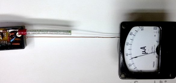
For more precise tuning of the transmitter and obtaining maximum power from it, it is recommended to manufacture and use the simplest RF detector, but this is a different story.
8. Final assembly
Putting the device into the case.
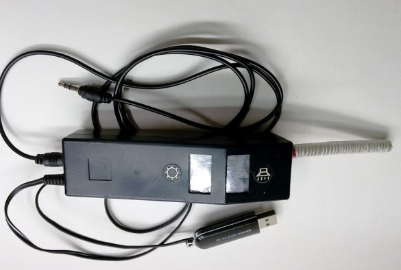
To reduce interference, it is advisable to connect the transmitter to the line-out of the TV with a shielded multicore cable.
After assembling and checking the settings, it remains only to check the range and sound quality.
Thus, the main task is completed. With the help of the manufactured FM transmitter, we have the ability to wirelessly transmit sound for television or computer broadcasts. In this case, when listening to TV programs on headphones, you will not interfere with other people, the loud work of the TV. The transmitter power is small, but it is enough for reliable signal reception within the apartment.
The scope of this simple but useful device is wide - it also transmits sound from a player or computer to a music center, the ability to watch 2 TVs or a TV and a computer in one room, and also use it as a regular car transmitter.