
You wrote in the program for Arduino something like:
lcd.print ("Hello, World!")The board obediently executed the command, and the text appeared on the display. But how did one device “say” something, and the second “hear” and “understand”? This is like asking the artist to make your portrait, but not see how he works on it. The author of Instructsbles under the nickname indoorgeek came up with a stand that will help you feel in the shoes of the “living Arduino” and steer the HD44780 at a low level. In one of the contests, this homemade won the first prize.
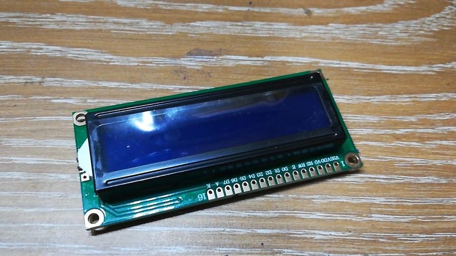
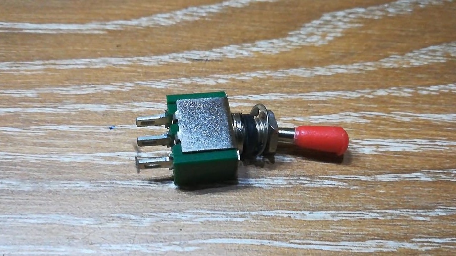
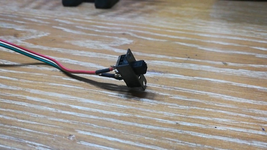
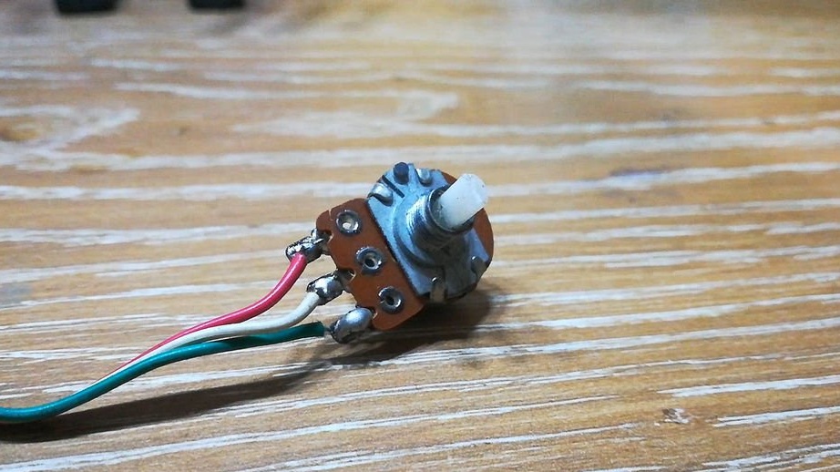
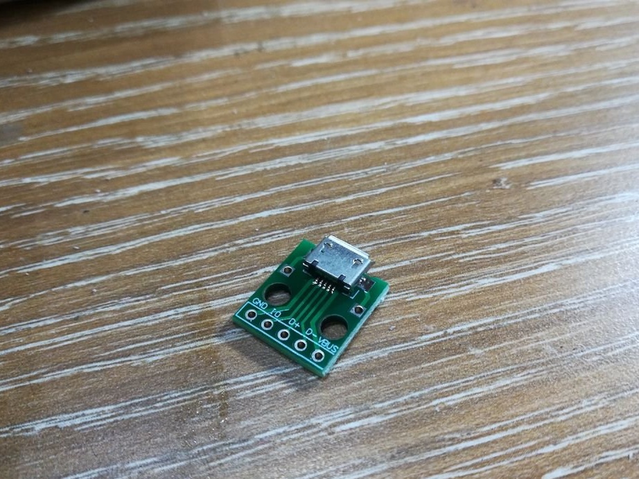
It needs a little detail: any module (LCD, VLI or PMOLED) on the HD44780 controller or compatible, eight toggle switches, a non-latching button, a slide switch, a 1 kΩ variable resistor, a board with a Micro USB socket and a case.
From what is not shown in the photo, we need: a resistor of 10 kOhm and a capacitor of 100 μF and at least 6.3 V.
Indoorgeek himself took a module of the most common type: LCD, 16 characters per line, two lines. But the rest of the modules have the same control principle, only the pinout may differ slightly, so don't be too lazy to look into the datasheet.
In all cases, the connection to the common wire corresponds to logical zero, and the connection to the +5 volt power bus corresponds to unity.
Pins 1 and 2 are for powering the module. The first of them is always connected to a common wire, and the second is always with a power bus.
Pin 3 is for adjusting contrast. When a voltage of 0 to 5 volts is applied to it relative to the common wire, the contrast changes from zero to maximum.
Pin 4 allows you to choose between a data register and an instruction register. We give a logical zero - the register of instructions (in other words, commands) is selected, the unit is the data register.
Instructions can be, for example, the following: initialize the controller, clear the screen, etc., and the data includes signs that you will display on the indicator.
You can, on the contrary, read data from some register. To do this, you need to apply a high level to pin 5, and the display will go into information output mode back to your microcontroller. To start writing data from your microcontroller to the display controller again, you need to send low level 5 to pin 5. Quite often, the reading mode is not used at all, as, for example, in this homemade product.
According to pins 7 to 14, the display can exchange commands and data in 8-bit encoding. The lowest level corresponds to pin 7, the highest - 14.
Pin 6 is needed for gating.You are slowly setting data on pins 7 through 14, but while pin 6 is a logical zero, the module does not respond to this at all. Then, without changing the state of pins 7 through 14, you send a high-level short-term pulse to pin 7 - and the data is transmitted.
Conclusions 15 and 16 - nutrition of the backlight, if any. 15 - plus, 16 - minus.
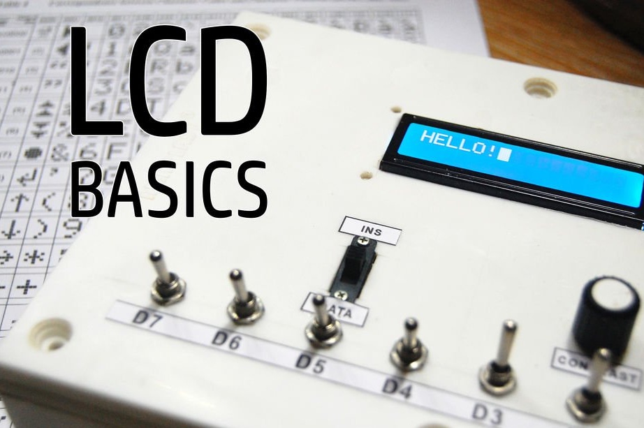
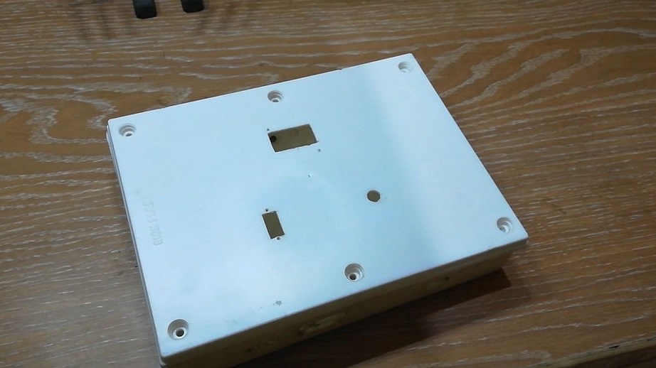
Available to indorgeek, the case turned out to be 200x150x40 millimeters in size. This case was taken from another, disassembled home-made, and there were already holes in it. The master used them in the new design to the maximum in order to do as little as possible additional ones.
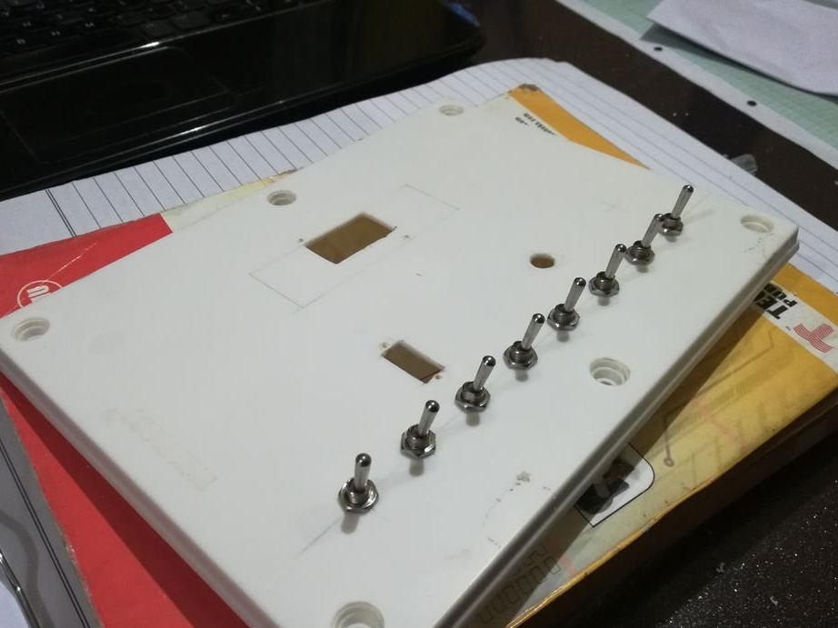
He set eight toggle switches for changing the state of the data / command bus lines, a switch for choosing between registers (see above), a button for gating, a variable resistor for continuously adjusting contrast.
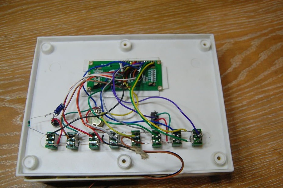
The riser board with a Micro USB jack has convenient pins that make it easy to connect leads. Only two of them are needed here: +5 V and a common wire. If you don’t have such a board, and a Micro USB socket soldered from somewhere seems inconvenient for soldering, you can just take a cord with a USB connector. In any case, let's repeat after the master and solder such a scheme:
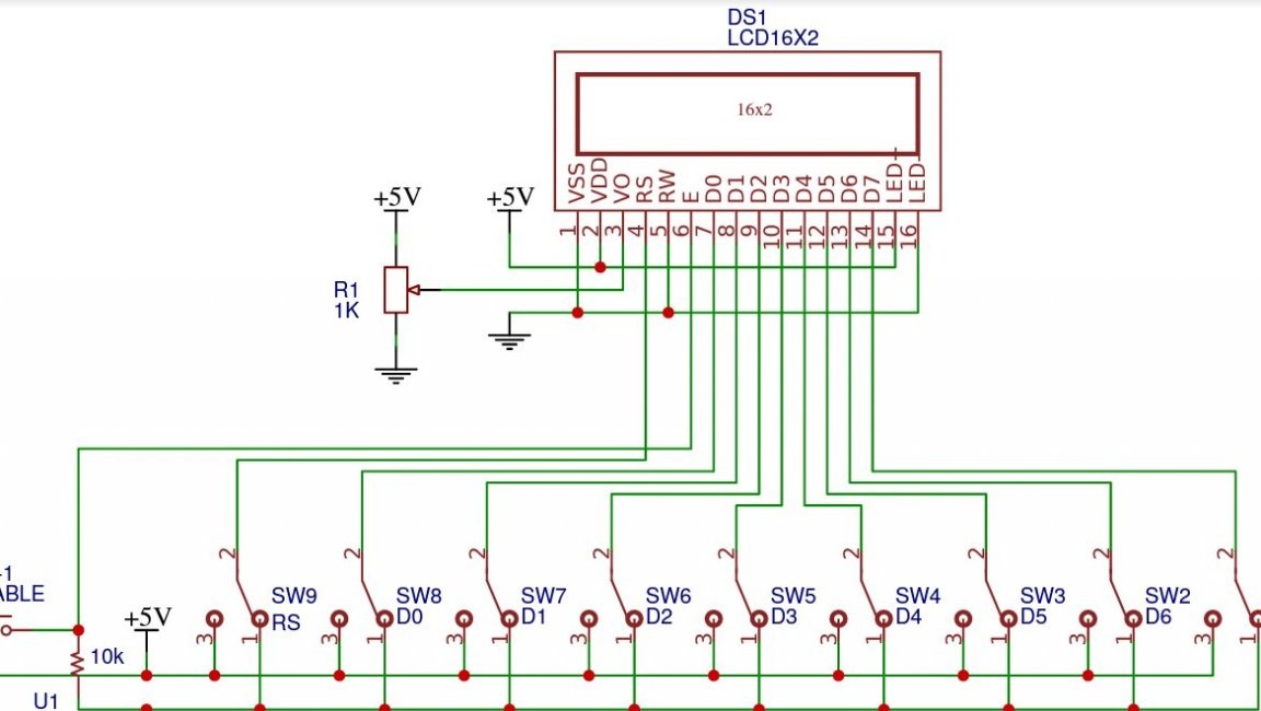
The contacts of the toggle switches corresponding to the upper position, indorgeek connected together and filed a plus on them. He did the same with the contacts of the toggle switches corresponding to the lower position, only he gave them a minus. He connected the movable contacts of the toggle switches not with each other, but with the conclusions of the data bus / module commands in accordance with the “weight” of both of them (D0 - pin 7 - low order, D7 - pin 14 - high). If the masters had not bitten enraged pull-up resistors in childhood, he would be able to use simpler toggle switches - not switching, but normally open.
But the same resistors, but in the suppression circuits of contact bounce, he was never offended. Here, this circuit is needed so that the display controller does not take one press of the strobe button for several. Other controls do not require chatter suppression, since as long as the strobe pulses are not received, the data on the remaining lines can change many times as desired. The main thing is not to touch the toggle switches and the switch with the button pressed. So, with a resistor of 10 kOhm, the master pulled pin 6 to the common wire, and with the button to the plus bus. Since the resistance of the button is much lower, when pressed, it “drags”. When released, its resistance becomes close to infinity, and the resistor is already “pulling” it. A 100 uF capacitor (not shown in the diagram), connected by a plus to the plus bus, and by a minus to the resistor and the sixth output of the display, suppresses chatter. It is better, of course, to suppress the chatter with a switch button and RS-trigger.
At the slide switch, the outputs of the fixed contacts are connected in the same way as for the toggle switches, and the movable one - to the output of the module 6. Here, the developer again showed a fear of pull-up resistors. This switch is needed to choose between the transmission modes of commands (zero) and data (unit).
Indoorgeek connected the output of the variable resistor corresponding to the minimum contrast to the common wire, the opposite to the plus bus, and the middle (engine) to the third output of the module.
Conclusions 1, 5 and 16 (respectively, minus power, write / read and minus backlight) the master connected to a common wire, so the recording mode is selected continuously. Conclusions 2 and 15 (respectively, plus power and plus backlight), he connected to the five-volt bus. A current limiting resistor through the backlight LEDs is integrated in the display module.
If you have collected all this, in front of you now - something like this:
The front panel indoorgeek designed so you can do the same:
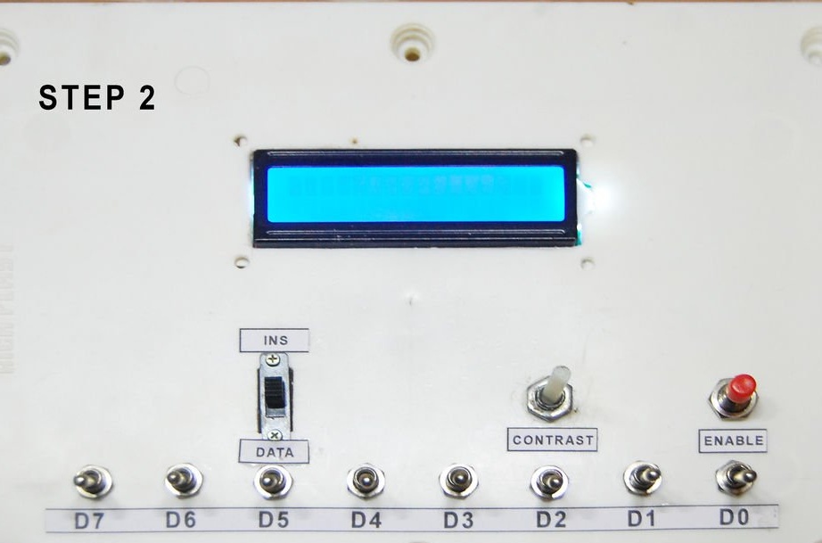
You can learn the HD44780 controller commands and how to control them by datasheet. You can also see ready-made script examples for simulator. For starters, we will repeat the steps behind indoorgeek to display HELLO!
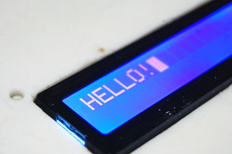
Turn on the device. The backlight will light up. Move the slide switch to the position corresponding to logical zero, so that the indicator switches to the mode of receiving commands. Set the binary number 00001111 on the command / data bus with the tumblers and briefly press the strobe button. This command means: turn on the display, make the cursor visible and blinking, which will happen. In the same way, we will issue the 00110000 command, which means: receive data in 8-bit format, select the first line and font 5 by 8 pixels. Visually, nothing will happen, but somewhere inside the display controller the necessary switches will occur. You can transfer data. We translate the slide switch to the position corresponding to the logical unit, now the indicator module is ready to accept them. Set the ASCII code of the letter H, i.e., 01001000, toggle the toggle switches on the bus and press the strobe button. The corresponding letter appears on the screen, and the cursor moves one position to the right. Similarly, we’ll pass the letters E, L, L, O and an exclamation point: 01000101, 01001100, 01001100, 01001111, 00100001. If you did the same thing, it doesn’t matter on the stand you just assembled or in the simulator, you will see the HELLO inscription ! Like this:
This is how you understood how much Arduino does in order to display just a few characters. And there are teams to perform more complex actions, having mastered which, you can get interesting effects, define non-standard characters ...
Your excursion to the "kitchen" of the Arduino library LiquidCrystal is just beginning, and let it be fun!