In a recent article “Home-made FM transmitter for wireless sound transmission"Talked about how to make do it yourself simple transmitter (transmitter) operating in the VHF FM band 88 ... 108 MHz. The radio transmitter is designed for wireless transmission within the apartment, high-quality sound accompaniment of television broadcasts or computer broadcasting to headphones, which allows you not to disturb others with a loud sound.
In this article, the establishment of this device after manufacturing and assembly is carried out by changing the parameters of the circuit, with quality control of the transmission and reception of the signal (sound) by ear.
This option of preliminary adjustment of the design of the radio transmitter is quite acceptable and the transmitter will work, but it will not reveal the maximum of its capabilities. But even this simple scheme will not be easy to configure correctly, without special devices. Not everyone has professional, sophisticated and expensive devices, but there is a way out in this situation. For a more detailed tuning of the radio transmitter, you can assemble a simple detector (indicator) of high-frequency (HF) radiation.
This detector allows you to determine the operability of the transmitter. He can determine if the transmitter has high frequency radiation, or more simply, if the transmitter is working and if it is generating any signal. This is especially true in the initial stages of setup.
Of course, the HF detector will not show the frequency (for this you can use the usual digital FM radio in your smartphone), but with it it is possible to objectively assess the presence and level of the emitted signal at the moment. With the help of this detector, it is possible to identify whether changes in the circuit have positively or negatively affected, as well as to adjust the transmitter to the maximum of the emitted signal.
Since this RF detector also responds to radiation from a mobile phone, it can be used to analyze the operation and repair of telephones.
Therefore, for everyone involved in the manufacture of various radio bugs and wiretaps, modulators and jammers, and even more so for fine-tuning the transmitter (the above design or any other in the FM band) and getting the maximum power from it, it is recommended to manufacture and use the simplest RF detector.
The main advantage of such an RF detector is its simplicity of design and lack of power. It turns out almost an eternal device.In addition, it will take only 1-2 hours to make it.
RF detector circuit
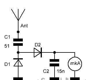
The operation of the RF detector is quite simple. When turned on, the radio transmitter emits radio waves that are detected by the detector antenna. In this case, the probe probe does not touch the antenna or the transmitter board, but catches the RF radiation at a certain distance. Since the detector circuit is maximally simplified and does not have an amplifier, this distance is small. The current induced in the antenna is rectified, smoothed and supplied to the measuring device, which roughly shows the level of radiation power of the transmitter. Thus, it is possible to determine the operability of the circuit of any transmitter in the range of FM frequencies.
Details
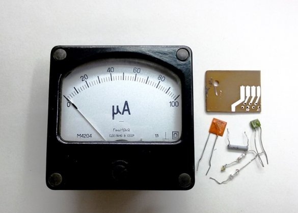
The basis of the HF detector is a measuring device - a microammeter at 50-100 μA. For work it is not so important, it will be a pointer device or a digital multimeter. But when taking readings, a dial indicator has some advantages. Since the magnetoelectric system of the pointer device has an inertia, the pointer of the device smooths out signal jumps and working with the device becomes more comfortable.
Almost every master in the household has dial gauges - voltmeters, ammeters, microammeters, left over from old equipment. Most often, if you open the case of the device, even if it is at a high current or voltage, and remove the shunt inside it, this device can turn into the microammeter you need. It remains only to determine the measurement limit of this device.
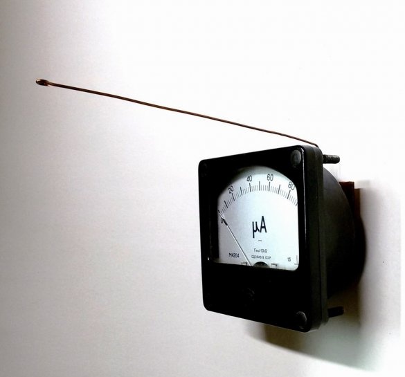
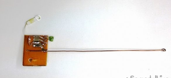
The design of the RF detector can be any. Hinged mounting on a board mounted on the device or a small plastic box where a dial indicator and other parts will be placed, with the antenna brought out. As an antenna, we use a piece of copper wire with a diameter of 0.8 ... 1.0 mm and a length of 150 ... 200 mm.
We use two ceramic capacitors in the device, the first at 51 pF (510), and the second at 15 nF (153), some deviations of the nominal values are permissible.
The circuit also needs two high-frequency silicon diodes KD503A. It can be replaced by KD521, KD522, etc. or an import analogue of 1N4148. The operating frequency of the diodes is from 100 to 350 MHz. Domestic high-frequency diodes are usually available in a glass case with flexible leads. Such diodes are widespread and are often found on boards with parts. Ring the diodes with a multimeter before using.
RF detector manufacturing
1. We select a suitable microammeter and parts according to the scheme. Let's make a circuit board from a piece of a universal board. Since we will only use the RF detector periodically, we will make the detector board functionally complete and quick-detachable. This will allow you to use the microammeter for other purposes and at any time, it is enough to remove the board from the device. Mobility of the detector board will give a hole in the corner of the board drilled for installation on the threaded terminal of the microammeter. It is possible to mount the board on both terminals of the device. The dimensions of the board should provide the ability to place the circuit between the terminals of the microammeter and preferably not protrude beyond the device.
2. We carry out installation and soldering of parts on the circuit board. From a piece of copper wire with a diameter of 0.8 ... 1.0 mm and a length of 150 ... 200 mm, we produce the receiving antenna of the detector. We fix mechanically one end of the antenna on the board (insert the end of the wire into the hole and pinch it on the other side) and solder it at the desired point above. To ensure safety when using the detector, collapse the other end of the antenna with a ring.
3. To accommodate as large parts as possible with the small size of the board and device, mounting parts is possible on both sides of the board. If there are no tracks on the board for contact with the terminals of the device, they can be made from the mounting wire.
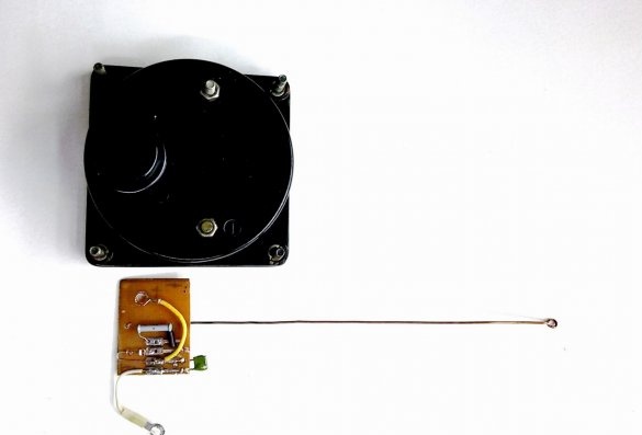
4.We install the detector board on one of the terminals of the device and fix the conclusions on the microammeter with the available nuts.
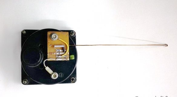
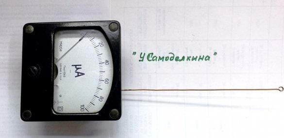
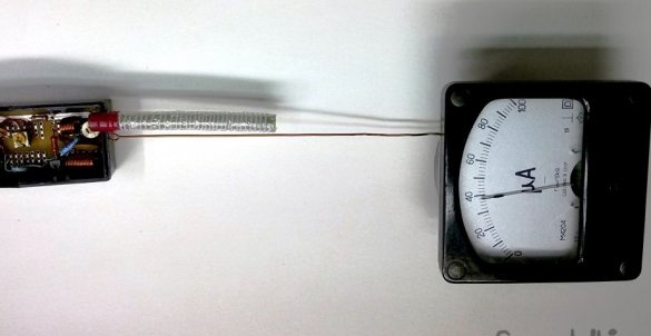
5. Using the manufactured RF detector, we measure the radiation from a newly assembled FM radio transmitter. Since the detector is always ready for operation, we bring (without touching) its receiving antenna to the transmitting antenna of the included radio transmitter. Depending on the radiated power of the transmitter, the arrow of the detector is proportionally deflected by an appropriate angle.
We repeat the same settings for the FM radio transmitter as in the previously mentioned article. But in the presence of undistorted sound in the receiver, we carry out additional tuning in this range for the maximum signal power. We perform this operation in all four configuration steps. Thus, we achieve loud and high-quality sound in the receiver, with maximum power and range of wireless sound transmission from the FM radio transmitter.
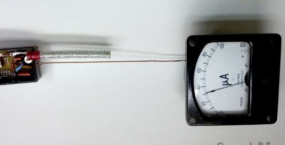
For example, another photo. It shows how the radiated power of the FM transmitter has changed, with increasing supply voltage from 5V to 7V.