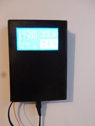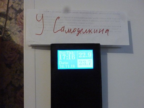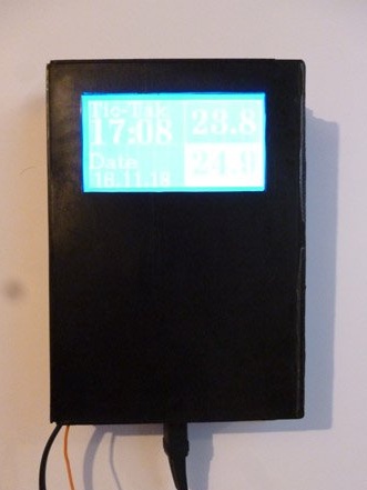
Good afternoon, i keep doing Arduino in his spare time, and this time he wrote instructions for the manufacture of a small weather station. It will act as a clock with a date and show temperatures inside and outside the room. As the main controller, we will use Arduino UNO, but another board with Atmega328p on board will do. For display we use the graphic screen WG12864B. We also connect two ds18b20 temperature sensors. One indoors, we take out the second outside. Let's get started.
In the manufacturing process homemade we will need:
- Arduino UNO (Or any other Arduino compatible board)
- WG12864B graphic screen
- ds18b20 temperature sensor, 2pcs
- Power supply 6 - 12 V
- Resistors 4.7 Kom 0.25 W, 2 pcs.
- Resistors 100 ohms 0.25 W
- Battery compartment for 4 AAA “pinky” batteries
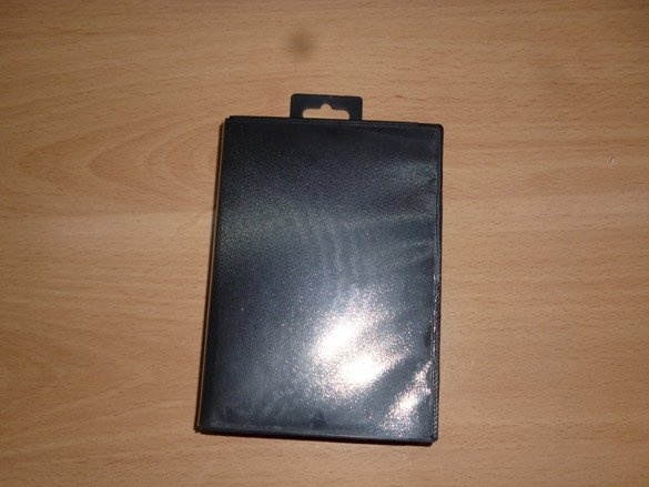
- Box from the cartridge of the SEGA console
- electrical tape
- connecting wires
- Circuit board
- Buttons
- Stationery knife
- soldering iron
- Solder, rosin
- Double sided tape
Step 1 Preparing WG12864B3.
Those who have not worked with screens before may be frightened by a large number of modifications, which seem to be the same, of screens. I will explain a little. Most screens of this type work on ks0107 / ks0108 chips. All screens can be divided into 4 types:
Option A: HDM64GS12L-4, Crystalfontz CFAG12864B, Sparkfun LCD-00710CM, NKC Electronics LCD-0022, WinStar WG12864B-TML-T
Option B: HDM64GS12L-5, Lumex LCM-S12864GSF, Futurlec BLUE128X64LCD, AZ Displays AGM1264F, Displaytech 64128A BC, Adafruit GLCD, DataVision DG12864-88, Topway LM12864LDW, Digitron SG1286464J-1, QY1286464JF, 2 QY
Option C: Shenzhen Jinghua Displays Co Ltd. Jm12864
Option D: Wintek-Cascades WD-G1906G, Wintek-GEN / WD-G1906G / KS0108B, Wintek / WD-G1906G / S6B0108A, TECDIS / Y19061 / HD61202, Varitronix / MGLS19264 / HD61202
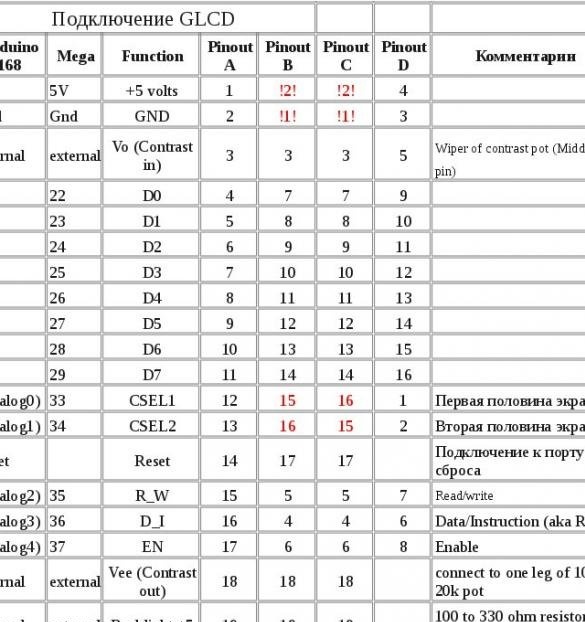
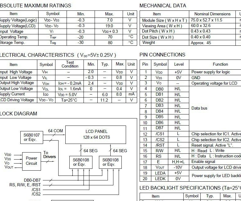
They look almost the same. But they have different connection pins. I chose, and I recommend you, WG12864B3 V2.0, but if the screen came in differently, or you just don’t have it at hand, you can easily figure it out using the table:
Brief characteristics:
There are many different connection schemes on the Internet, and everything seems to be working. The thing is that there are not only different screens, but also two ways to connect them: serial and parallel. When using a serial port connection, we need only 3 outputs of the microcontroller. With a parallel minimum of 13. The choice in this case is obvious, Arduino has few conclusions. For parallel connection, the connection diagram is as follows:
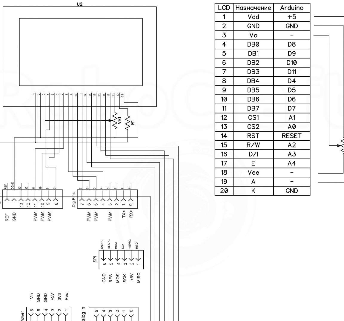
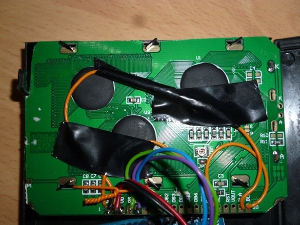
For a serial connection, which we will use, the scheme is as follows:
WG12864B - Arduino UNO
1 (GND) - GND
2 (VCC) - + 5V
4 (RS) - 10
5 (R / W) - 11
6 (E) - 13
15 (PSB) - GND
19 (BLA) - via a 100 Ohm resistor - + 5V
20 (BLK) - GND
To adjust the contrast, a potentiometer should be on the screen. There are screens without it, but now it’s a rarity:
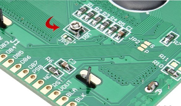
A 100 ohm resistor is needed so that a voltage of 5 volts does not accidentally burn backlight diodes.
Step 2 Making the case.
For the case, take the box from the cartridge prefix Sega. If you don’t find this box at hand, you can use another case. The main thing is that the screen and the Arduino fit in it.
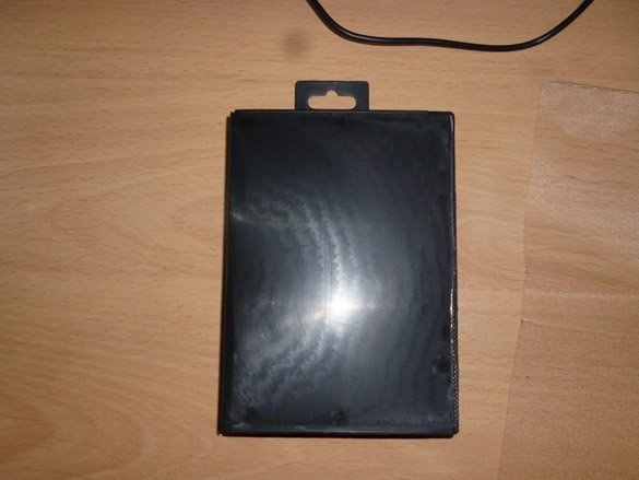
Cut the transparent film on top of the box so that there are no pieces left:
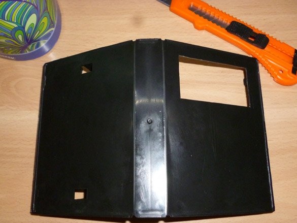
Then, using a clerical knife, cut out a window 37x69 in size for the screen.
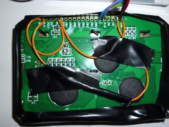
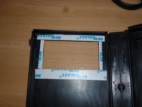
On the reverse side, along the edge of the cut, we glue a double-sided tape, preferably black:
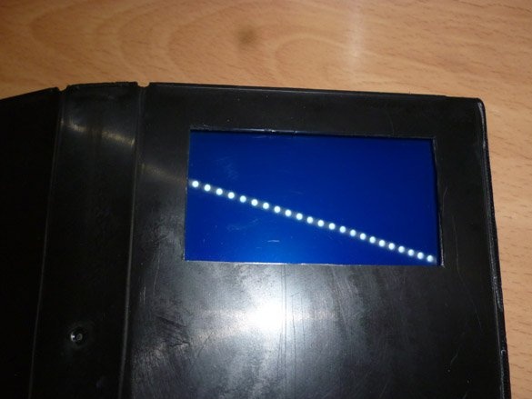
Remove the protective paper from the adhesive tape, and glue our screen on it:
From the outside it should look like this:
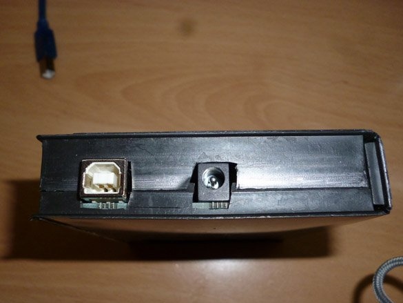
Below the screen, also on double-sided tape, we fasten the Arduino, making preliminary cutouts for the USB port and power socket:
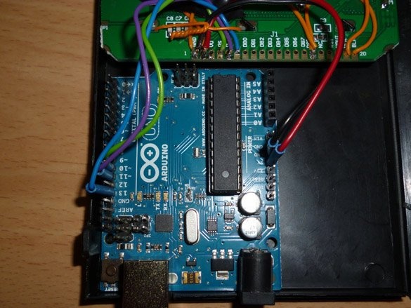
Cutouts for Arduino sockets must be done on both sides of the box so that it can be freely closed:
Step 3 Temperature Sensors.
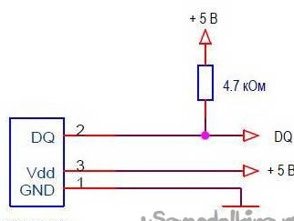
We will use digital temperature sensors DS18B20. Using them we get great measurement accuracy, the error is not more than 0.5 ° C, in a wide temperature range -55 ... + 125 ° C. In addition, the digital sensor performs all the calculations itself, and the Arduino simply receives ready-made readings. When connecting this sensor, do not forget about the pull-up resistor, 4.7 kΩ, between the DQ and VDD contacts. Several connection options are also possible. With external power, in my opinion the best option, we will use it:
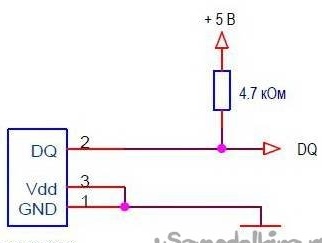
If you want, you can use the parasitic power mode:
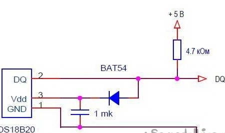
Or an improved parasitic food option:
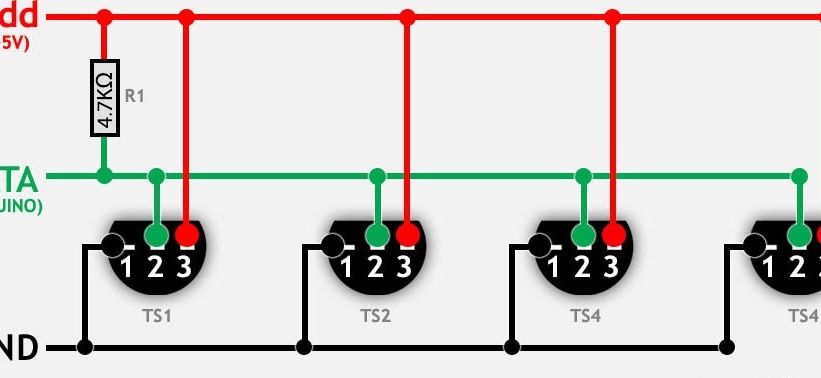
With any power supply, the sensors are connected in parallel:
We will place the temperature measuring sensor on the small board along with two buttons, which we will use to set the time and date of the clock:
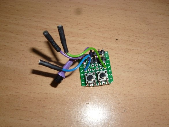
The common wire from both buttons is connected to GND, the wire from the first button is connected to A0, from the second to A1.
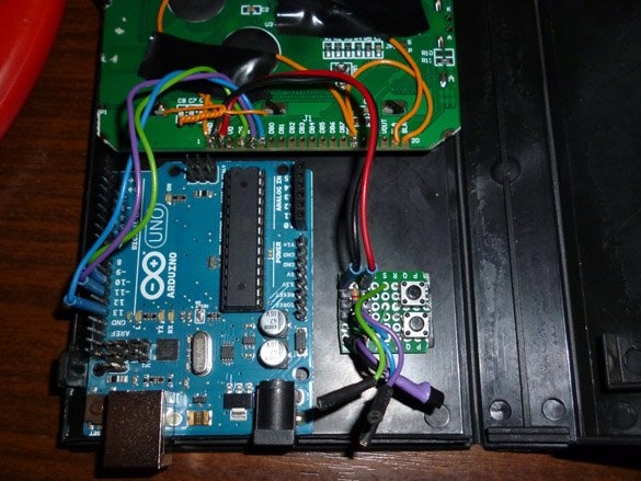
Fasten to a double-sided tape next to the Arduino:
The sensor, which is supposed to be placed outside the room, is better to choose in a metal, dust and moisture proof housing:
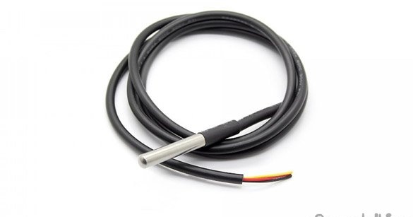
Calculate the wire of the required length so that the sensor can be hung outside the window, the main thing is that it should be no more than 5 meters, if you need more length, you will need to reduce the value of the pull-up resistor.
The wire from the DQ data bus of both sensors is connected to pin 5 of the Arduino.
Vdd - +5 Arduino.
GND - GND Arduino.
Step 4 Power.
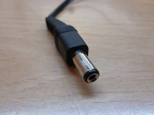
For power, you can use a power supply with a voltage of 6 to 12 volts. At the end of the power flare wire, solder the plug suitable for the Arduino power socket:
Or you can put a battery compartment for four “AAA”, “pinky” batteries in the case. And connect the positive wire from the compartment to the Vin Arduino, and the minus to GND.
Step 5 Preparing the programming environment.
First you need to download and install Arduino IDE with official site
And also add to the two libraries needed for the sketch. OneWire - required for communication with ds18b20 sensors:
U8glib - used to display information on the screen:
Download the library. Then we unpack the archives and move the contents of the archives into the “libraries” folder located in the folder with the Arduino IDE installed. You can also add libraries through the Arduino IDE. To do this, without unpacking the archives, run the Arduino IDE, select Sketch - Connect Library from the menu Sketch. At the very top of the drop-down list, select the "Add .Zip library" item. We indicate the location of the downloaded archives. After all the steps, you need to restart the Arduino IDE.
Step 6 Editing the sketch.
Temperature sensors operate using the One Wire protocol and have a unique address for each device - a 64-bit code. Adding sensor search commands to the sketch is not advisable. There is no need to load Arduino hiccup sensors every time.Therefore, first, putting everything together, fill in the sketch in Arduino, located in the File menu - Examples - Dallas Temperature - OneWireSearch. Then run Tools - Port Monitor. Arduino should find our sensors, write the addresses and temperature readings. These addresses need to be written down or just copied somewhere. Now open the sketch Ard_Tic_Tak_WG12864B_2_x_Term_Serial, and look for the lines:
byte addr1 [8] = {0x28, 0xFF, 0x75, 0x4E, 0x87, 0x16, 0x5, 0x63}; // internal address
byte addr2 [8] = {0x28, 0xFF, 0xDD, 0x14, 0xB4, 0x16, 0x5, 0x97}; // address of the external sensor
We replace the addresses corresponding to the location of the sensors with our addresses.
Our watches do not use the RTC (real-time clock) module, so you need to adjust the clock. For convenience, uncomment the line (seconds will appear on the screen):
//u8g.setPrintPos (44, 50); u8g.print (sek); // Print seconds to check the correctness of the courseSet the correct time through the port monitor. To do this, open the port monitor, wait for the initial temperature measurements to finish, and enter the current date and time in the format "day, month, year, hours, minutes, seconds." Without spaces, divide the numbers with commas or periods.
If the clock is in a hurry, change the value to a larger one, I recommend experimenting with increments of 100 units. If lagging, decrease the value in the line:
if (micros () - prevmicros & gt; 494000) {// change to another for adjustment was 500,000Empirically determine the number at which the clock goes quite accurately. To determine the accuracy of the course and need a conclusion seconds. After accurately calibrating the number, seconds can be commented out and thus removed from the screen.
Fill the sketch.