
This article describes the process of self-manufacturing a drilling machine for printed circuit boards. The author of this homemade product is Roman (YouTube channel "Open Frime TV")
The base of the machine is printed on a 3d printer. 3D model can download HERE. If you do not have a 3d printer - it doesn’t matter, you can use this case:
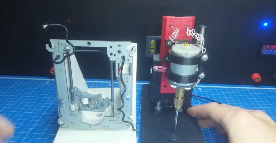
You will learn how to make such from this video.
In general, today's homemade product is an improved version of the drilling machine from the video above, so to say, the drilling machine version 2.0. Those who have not seen this video, be sure to watch.
So, what exactly has the drilling machine undergone? And the change is as follows:
1) Automatic speed control drill. When there is no load, the revolutions are minimal, as soon as the load appears, the revolutions increased to maximum, and then again fell. This, I tell you, is a very useful thing. Firstly, it reduces brush wear, and secondly, it makes it easier to aim when drilling.
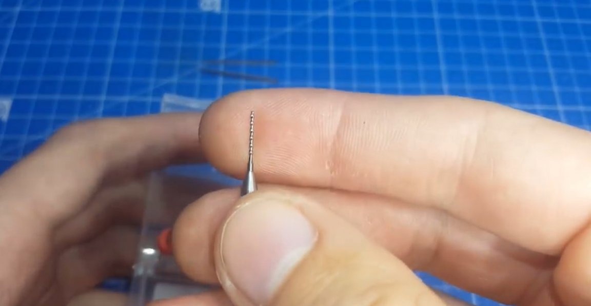
2) The next change is the drill. Prior to this, the author used ordinary drills for metal of the desired diameter.
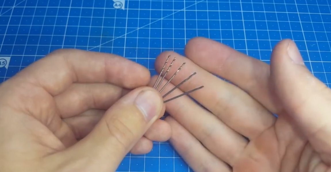
But for these purposes there are special cool carbide drills.
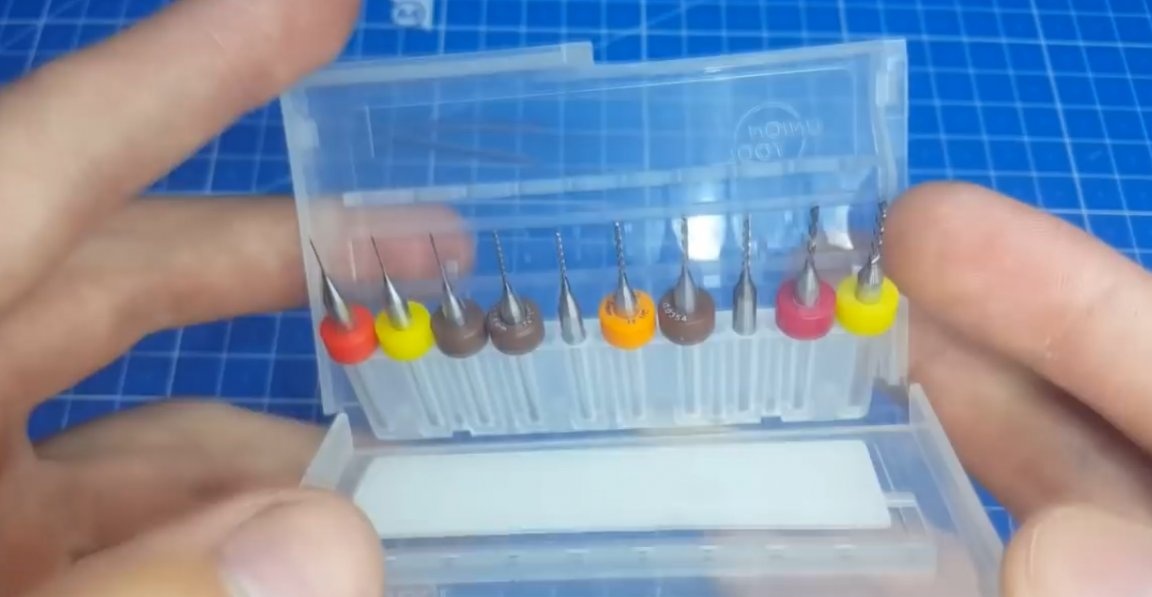
The author ordered them and realized how much these drills facilitated the drilling process. Firstly, they have a spiral shape and you won’t have dust scattered all over the table, and secondly, they blunt much longer than ordinary drills, which is a huge plus.
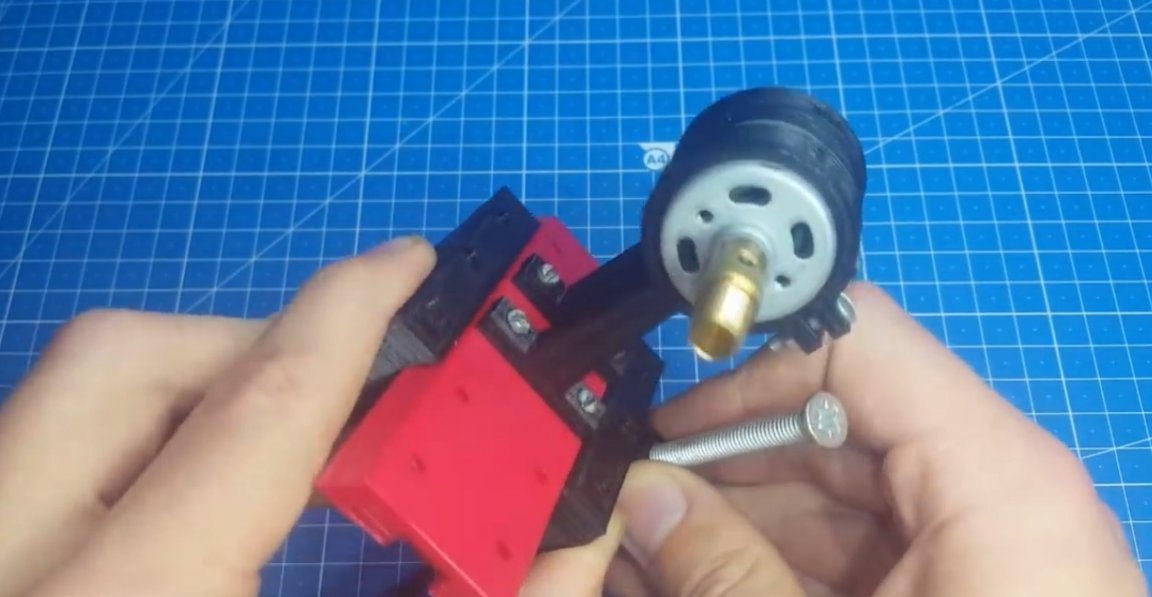
It was also possible to replace the collet chuck with a keyless chuck, it costs a little more, but the benefits are much greater, you do not need to constantly change the collet.

But since we have carbide drills in which all the tails are the same, you can leave this cartridge, there are no special problems with it.
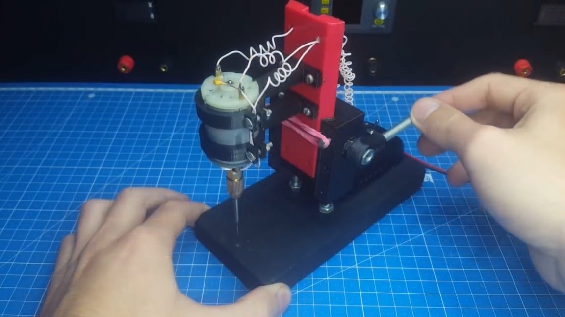
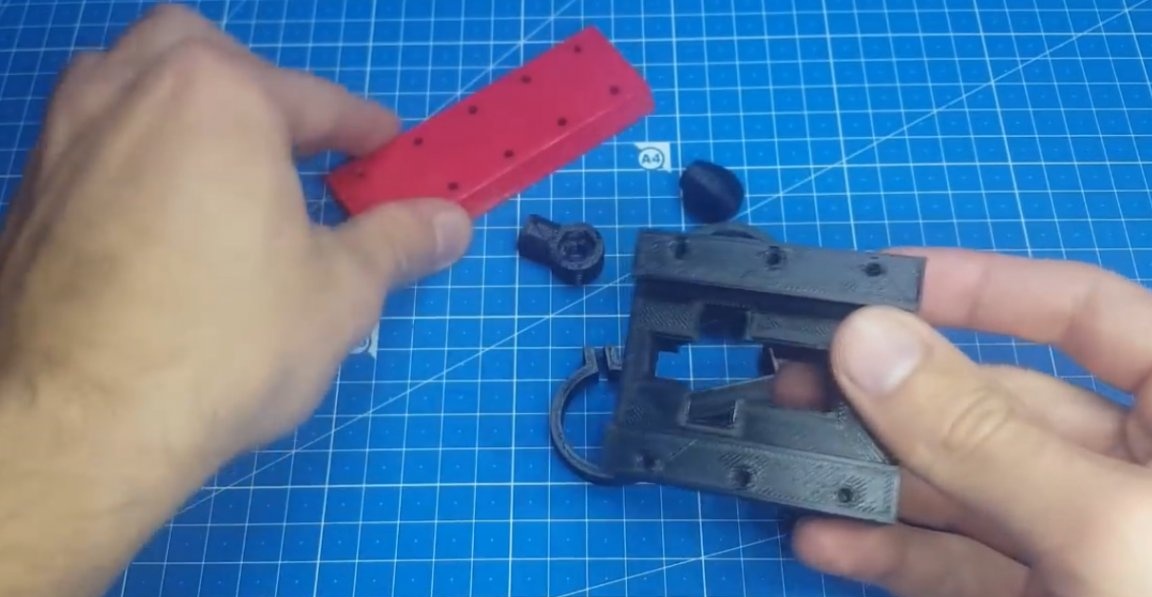
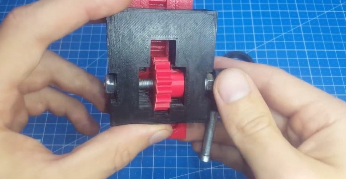
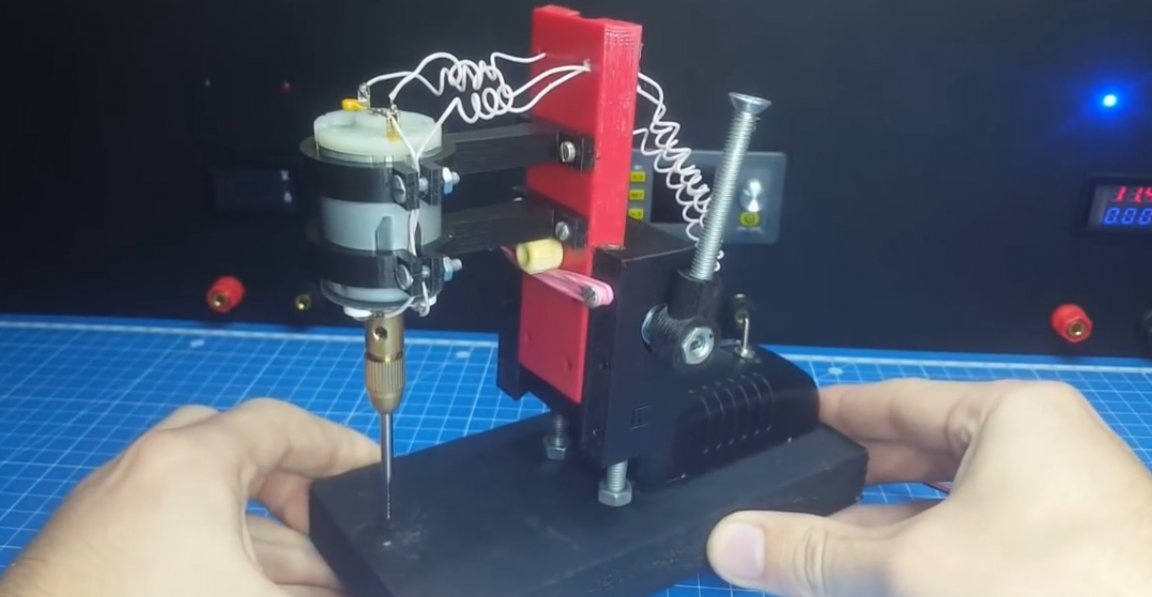
Now let's see how all this is implemented. The machine itself is going to be easy. We do everything according to the picture of the author of this model. We slowly assemble it by connecting the moving parts, and also lubricate them, since this is plastic and can easily be developed.
The only thing that is not provided for in the 3D model of the case is the stand, it will have to be made independently. The author made it of wood. She is quite weighty, as if she would not stagger.
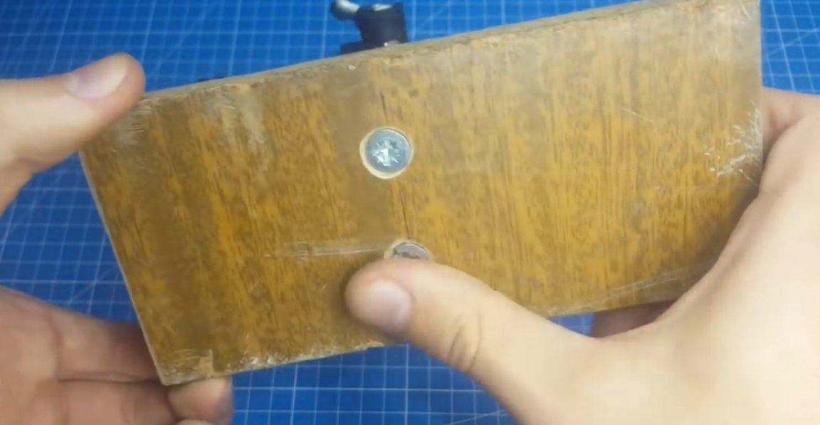
To give a beautiful look, the author also painted it black.
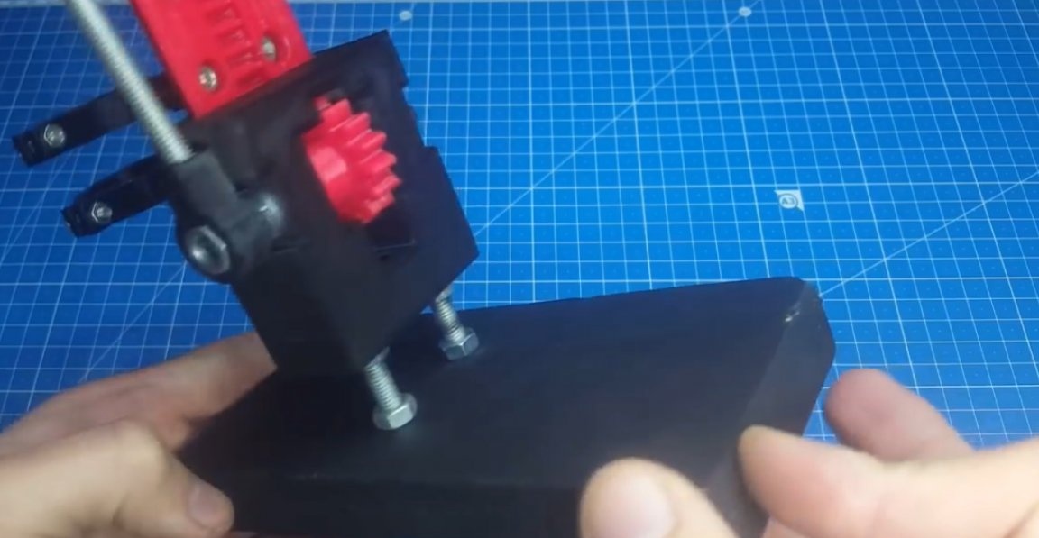
As you can see, it turned out no worse than the factory models.
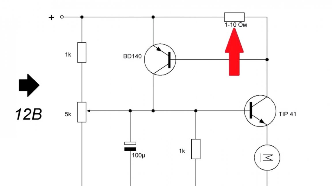
The next step is to consider a circuit for automatic speed control.
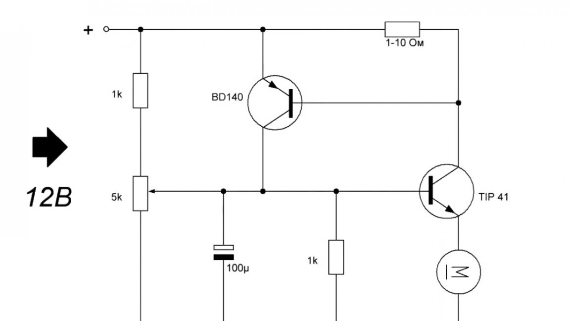
It is simple, only 2 transistors and a strapping.
It is desirable to put the power transistor on a radiator.
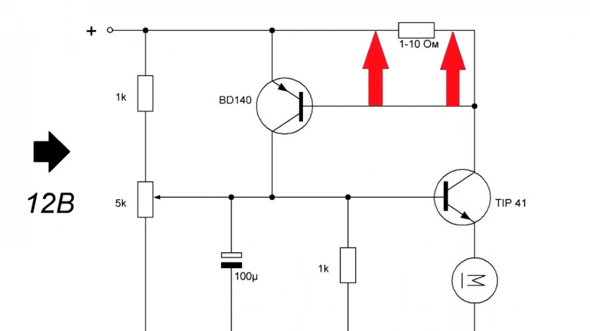
Let's see how this scheme works. Without load on the base of the power transistor, voltage comes from the trimmer resistor. This transistor is in the ajar state.
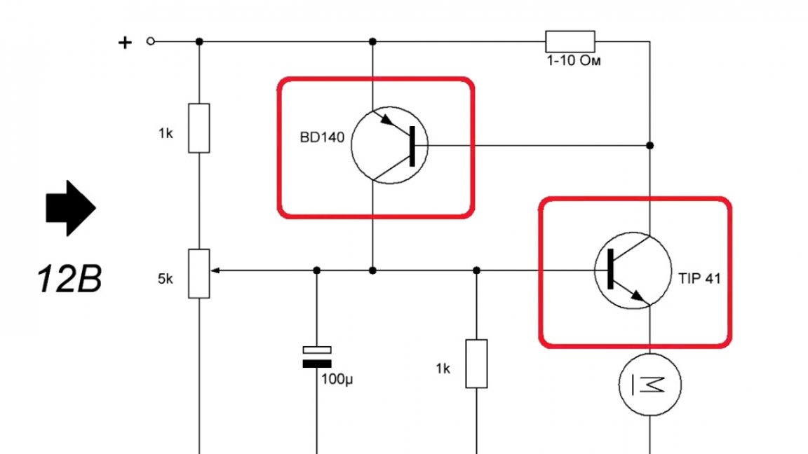
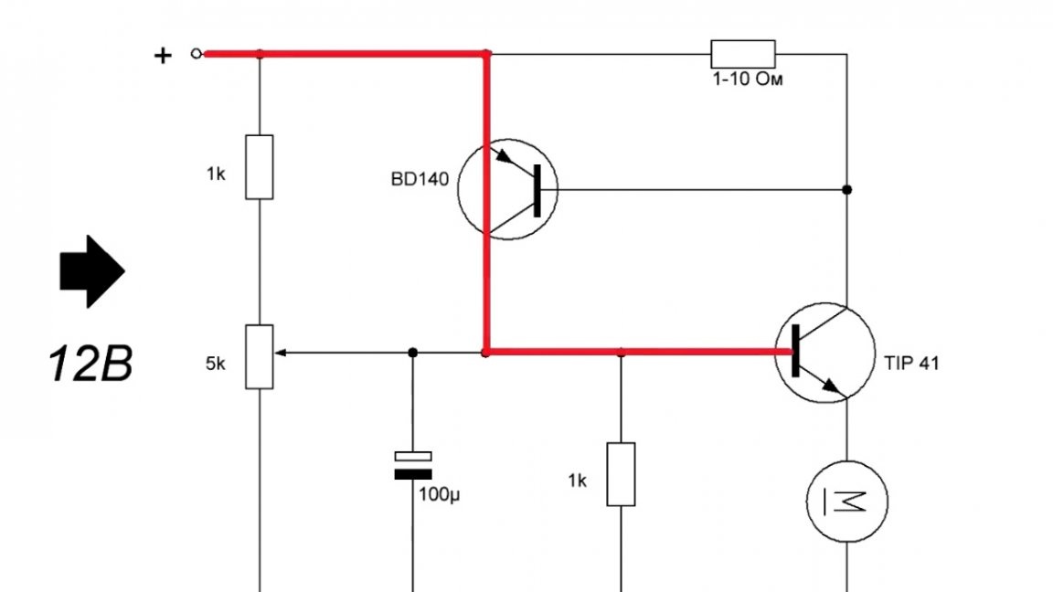
Now about what happens when the load is applied. On one leg of the shunt resistor, the voltage becomes less than on the other:
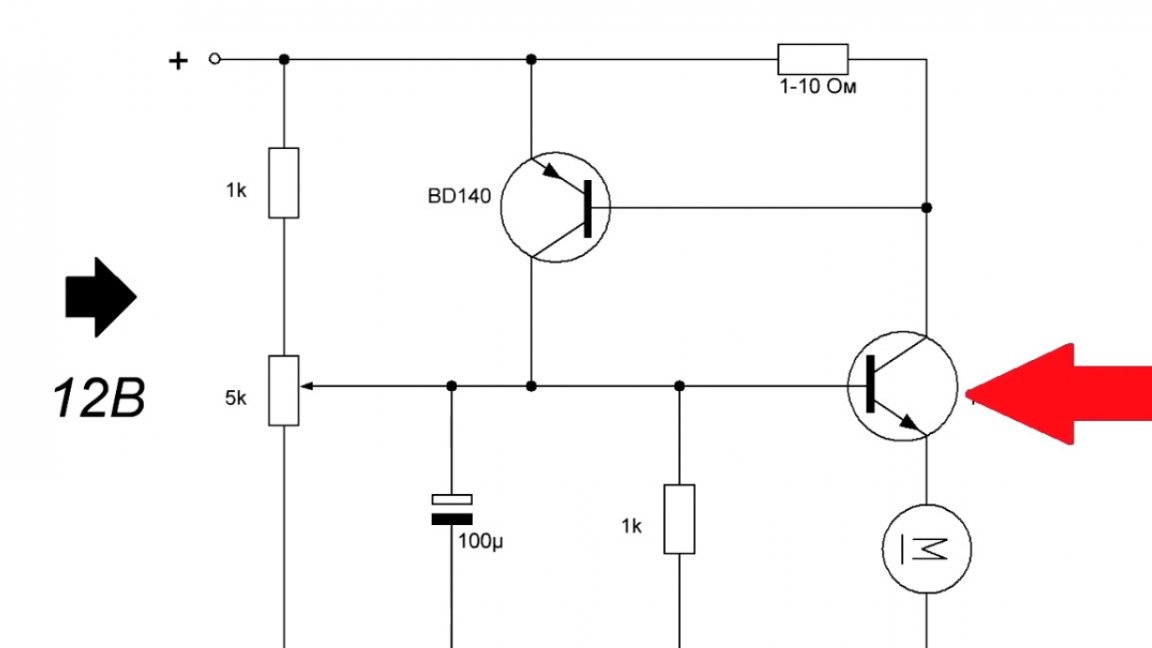
In this case, on the basis of the second transistor, the voltage becomes less than on the emitter, and it opens, pulling the base of the power transistor to the plus power. Accordingly, the power transistor opens at full power and the engine speed increases.
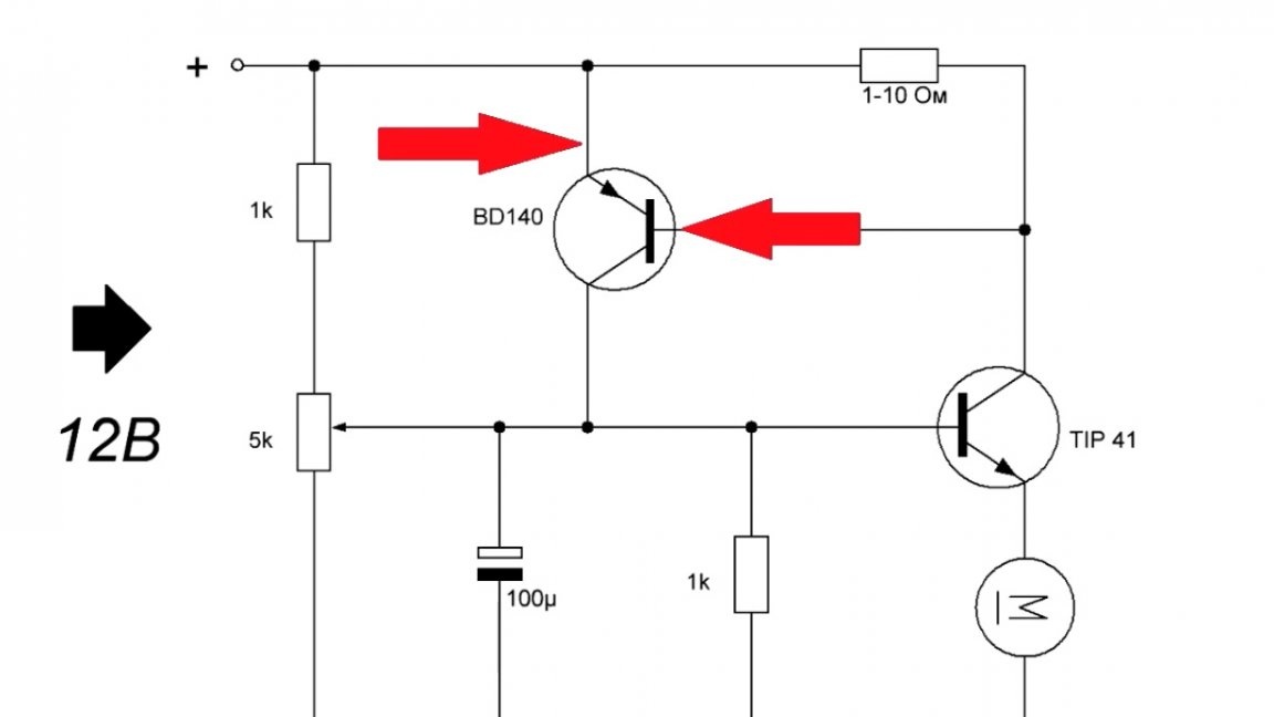
As soon as the load disappeared, the voltage difference became smaller, and the upper transistor closed. The engine again barely rotates. By changing the resistance of the tuning resistor, you can set the minimum engine speed.
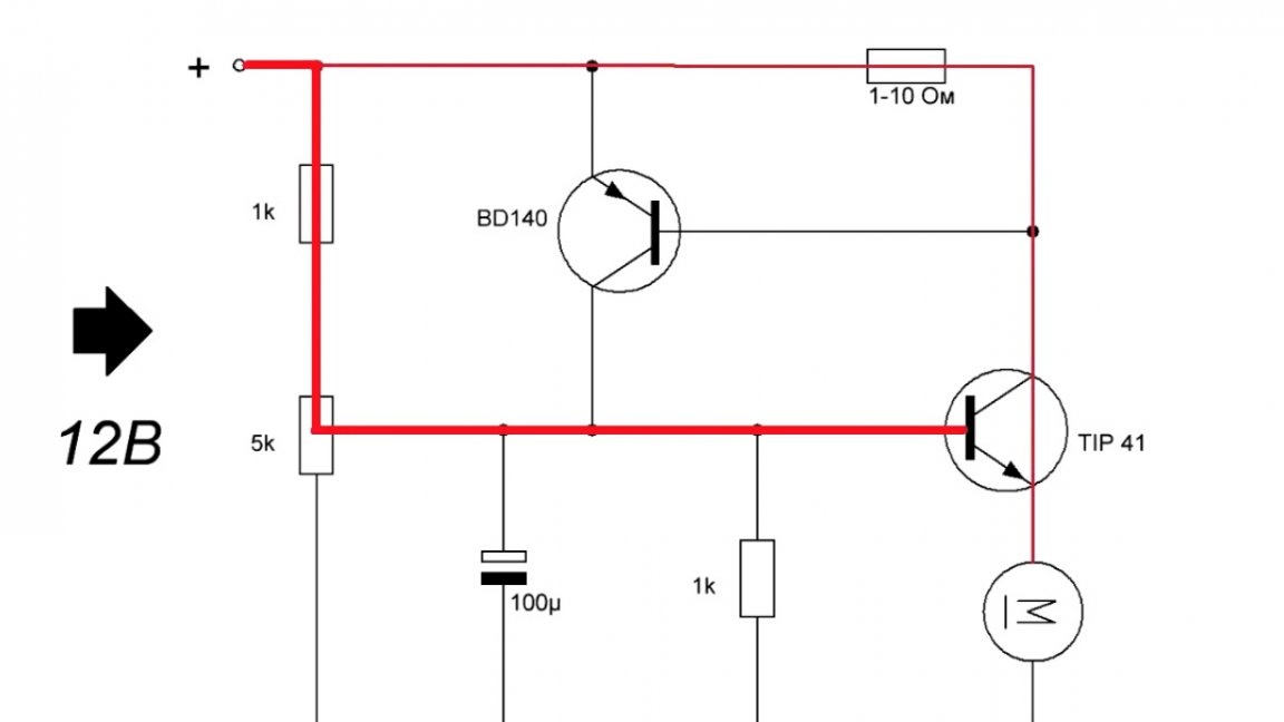
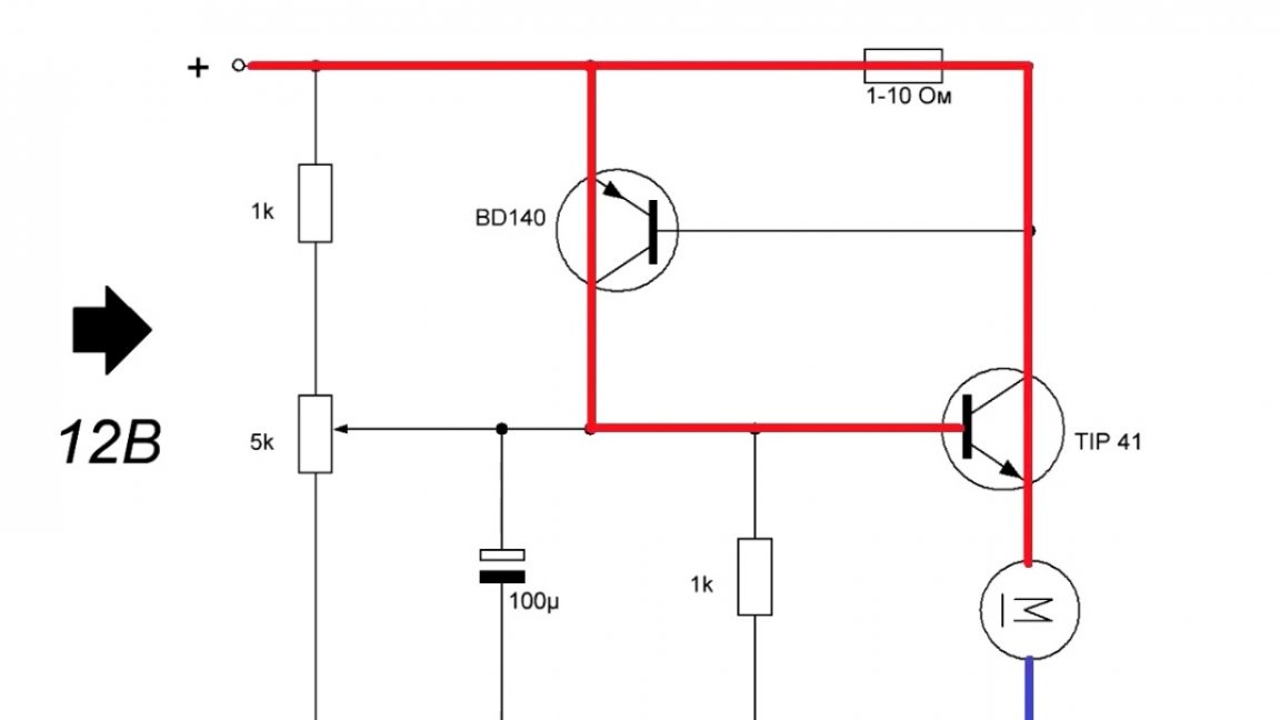
The only difficult task in this circuit is the selection of a shunt resistor.
If you take it with a larger nominal value, then the voltage will constantly drop on it, and, therefore, the lower transistor will always be open.
For different engines, the rating will be different. The author bought 10 resistors with a nominal value of 1 ohm to 10 ohms and began to try.
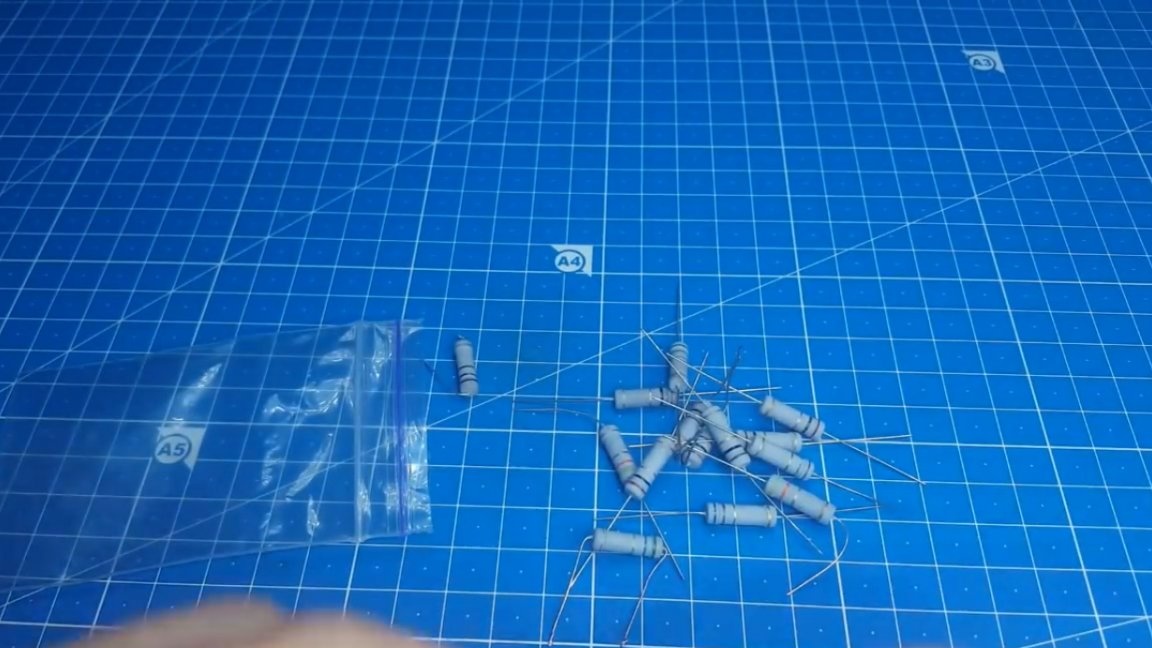
With a 2Ω resistor, optimal performance was achieved. And remember, the more powerful the motor, the less the rating must be taken.
Move on. The circuit board of this controller turned out to be very small. This can be assembled without any problems on the layout, but we will do it on a printed circuit board.
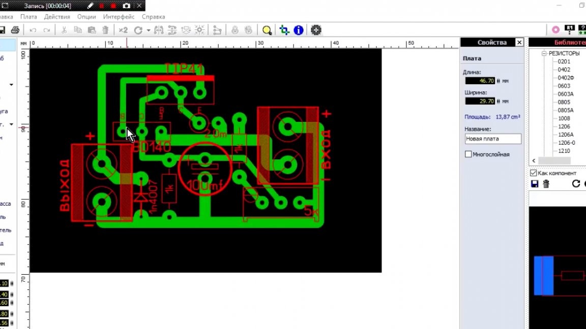
We solder a scarf.
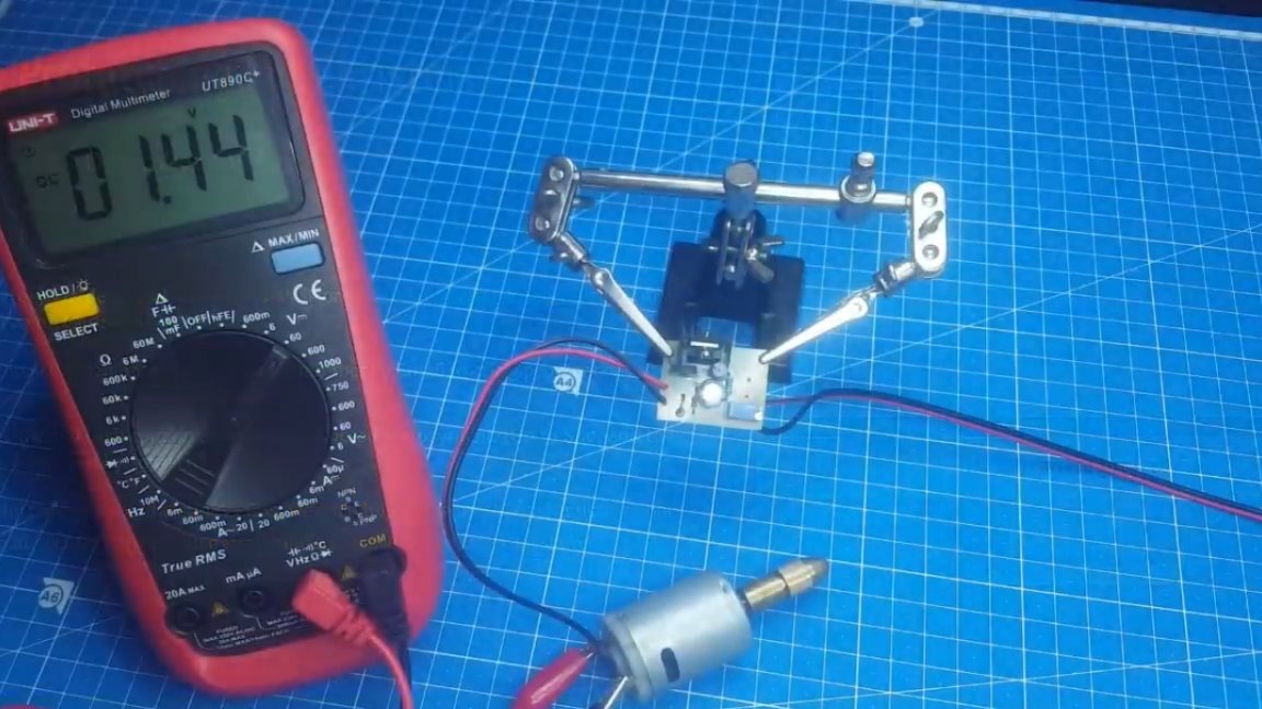
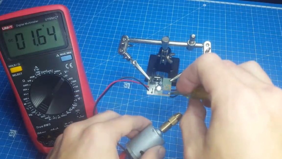
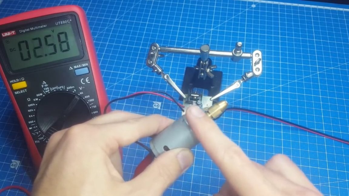
And so it works. As you can see, the multimeter captures the voltage directly on the motor.
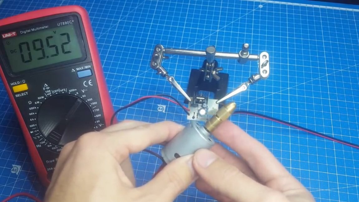
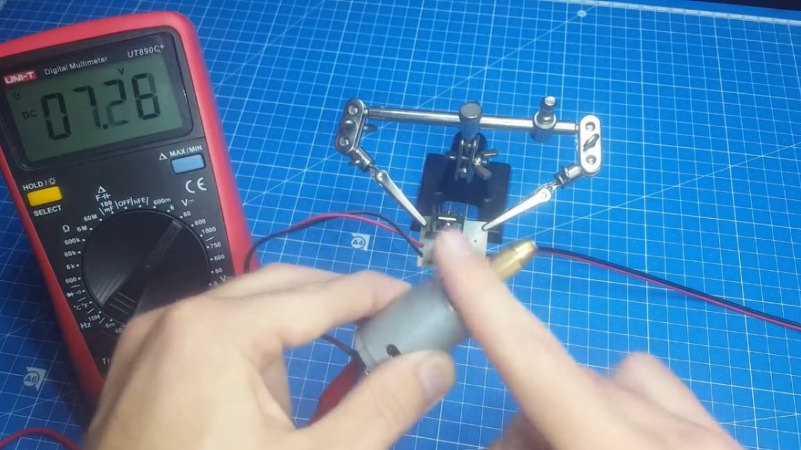
We touch the cartridge with a finger and the speed immediately increases. We remove the finger, and they fall to the set.
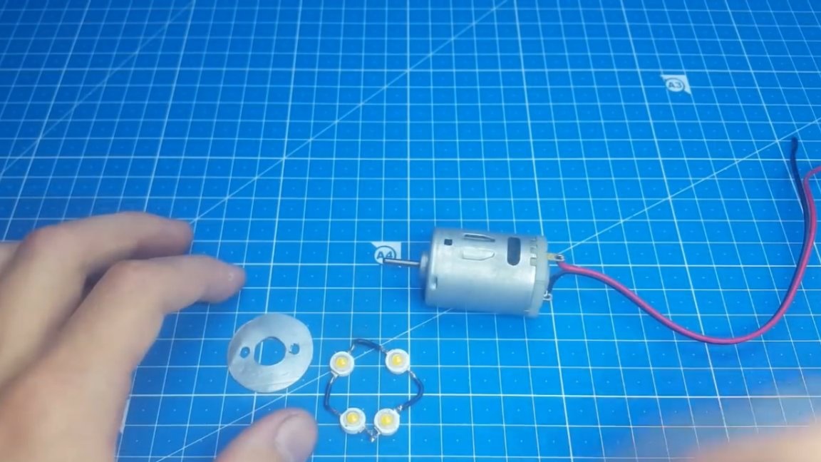
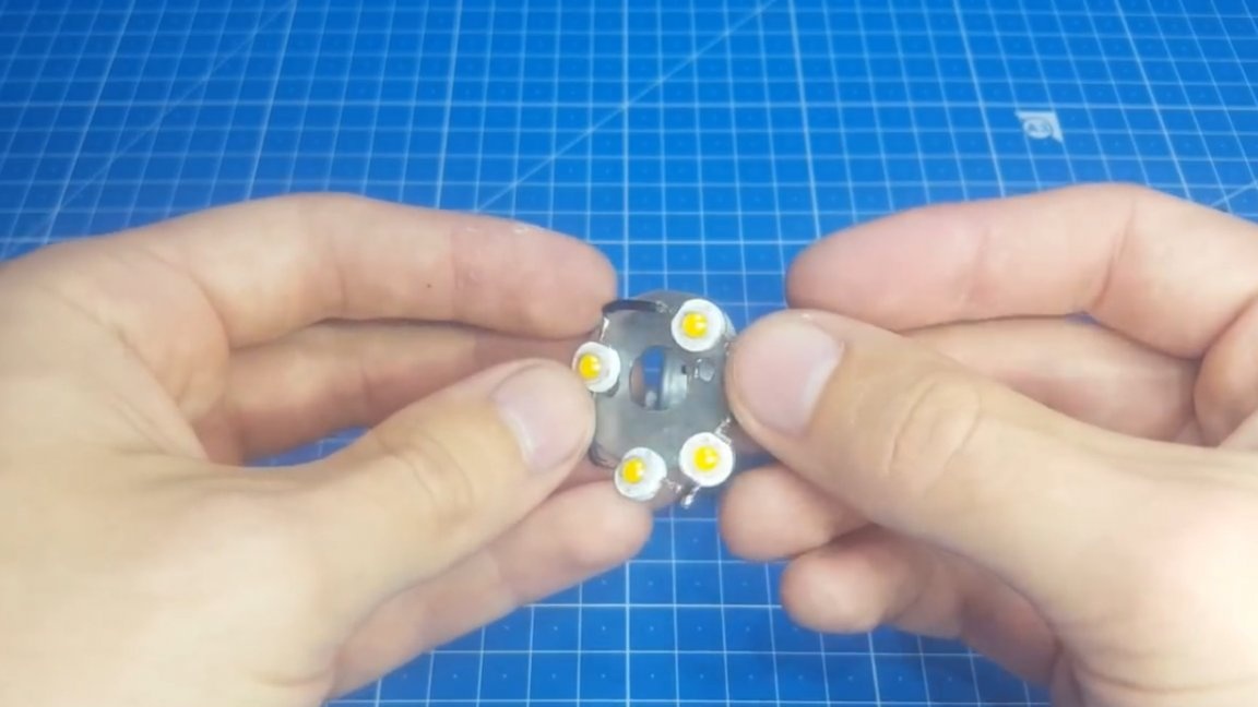
Oddly enough, with such a simplicity of the circuit, the operation is trouble-free. No changes in this project remained lighting. These are all the same 4 LEDs with a power of 1 W each located below the engine on such a radiator plate.
For beauty we’ll hide the circuit board, wires and a switch in the case. Here, the case from the old power supply is perfect.

We will drill the necessary holes in it and now it remains to connect everything together.

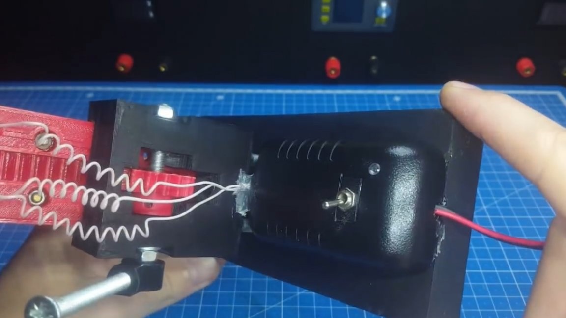
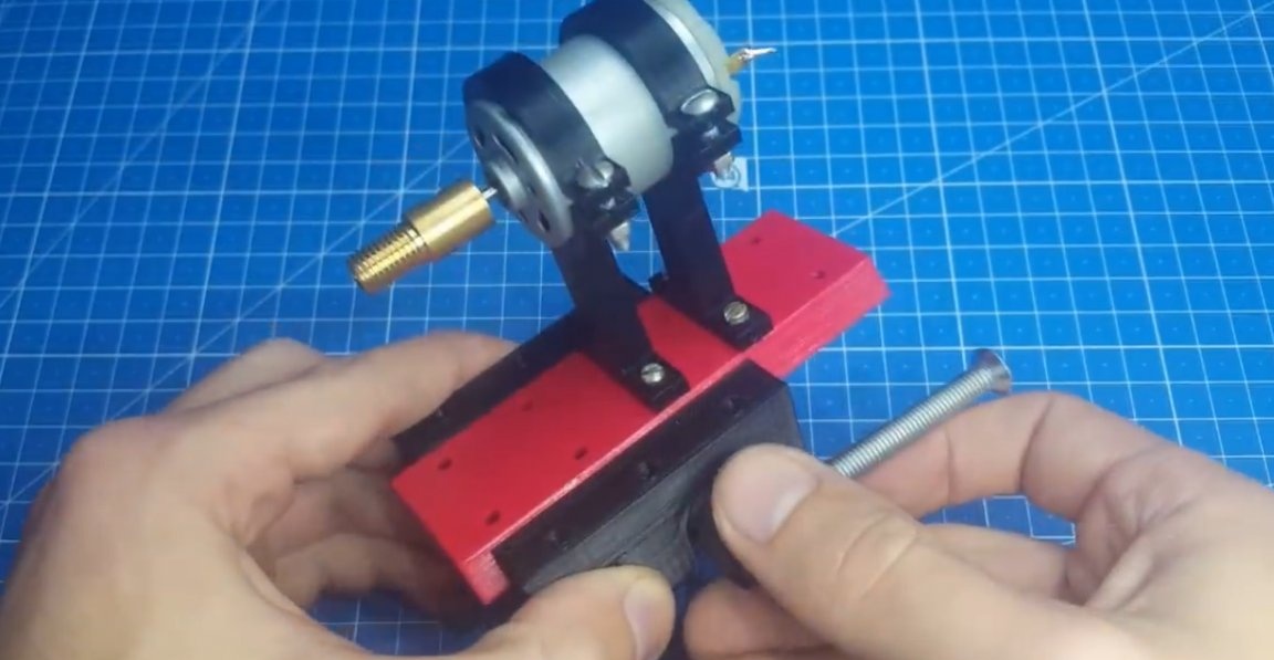
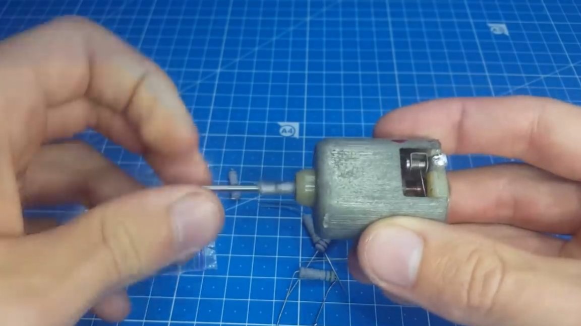
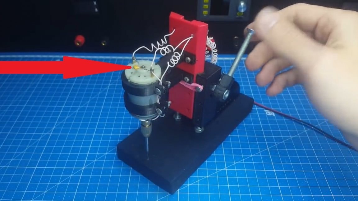
Well, we’ve gathered the stanochki. It turned out pretty nicely, not distinguishable from the factory model. As you can see, a capacitor of 100 nF is installed on the engine. When the brushes start to wear out, it will protect against false positives.
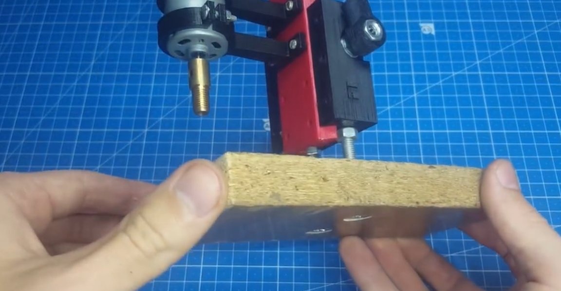
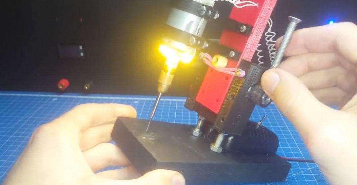
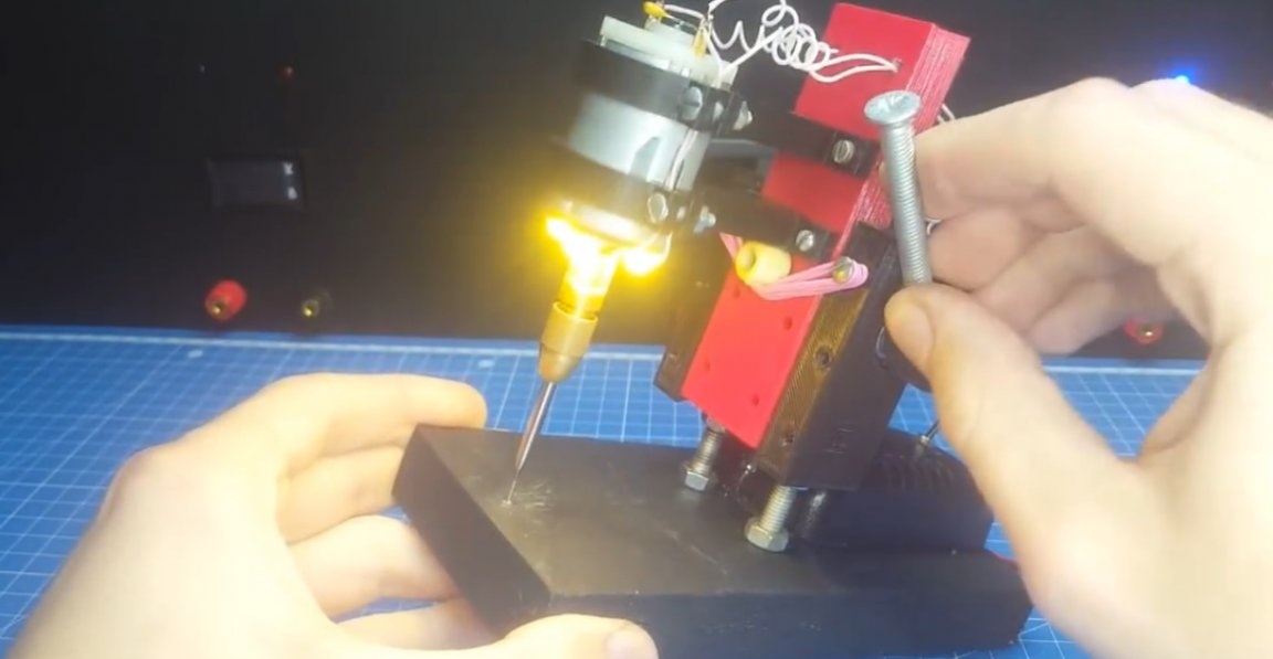
Well, in the end, you can test the machine. To do this, take some old board and try to drill. The author turned off the backlight so as not to blind the camera.
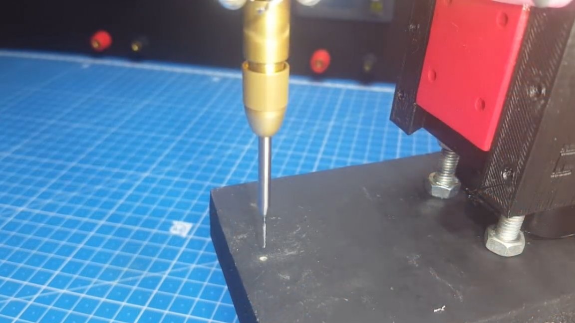
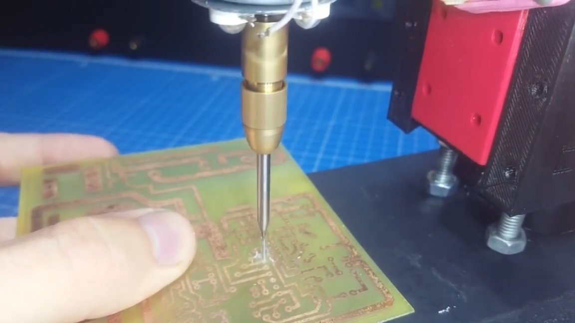
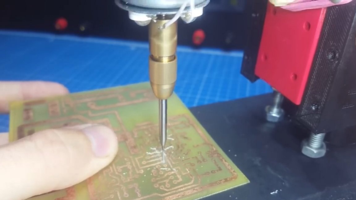
As you can see, the drilling process is just perfect. He aimed, gave a little load and easily drilled a hole.
Well, that’s all. Thank you for attention. See you soon!
Video: