
Today we will study the insides of the Tetris game written under the platform arduino and LED matrix.
The author of this homemade product is AlexGyver, the author of the YouTube channel of the same name. Welcome to the wonderful world of square pixels.
Let's start with the story. Tetris is a game in which figures consisting of 4 squares fall from top to bottom. In different combinations, these shapes can be rotated and moved left and right. The goal of the game is to collect horizontal levels that are cleared and points are awarded to you. Losing is considered the moment when the new figure has nowhere to fall. Tetris was invented by the Soviet programmer Alexei Leonidovich Pazhitnov.
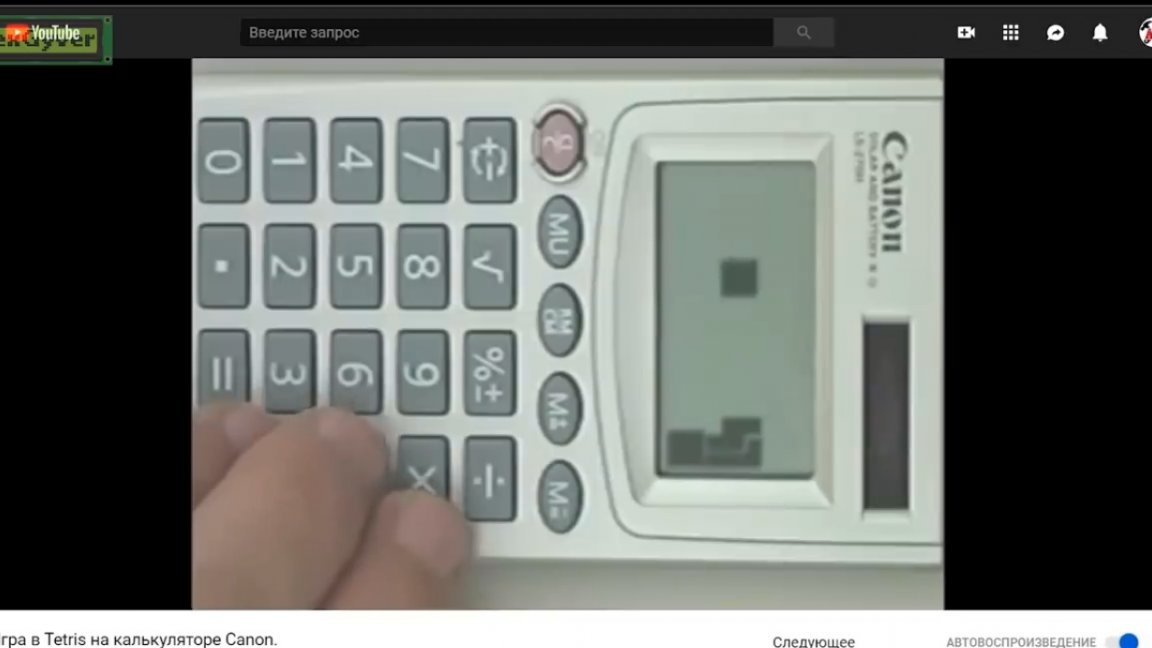
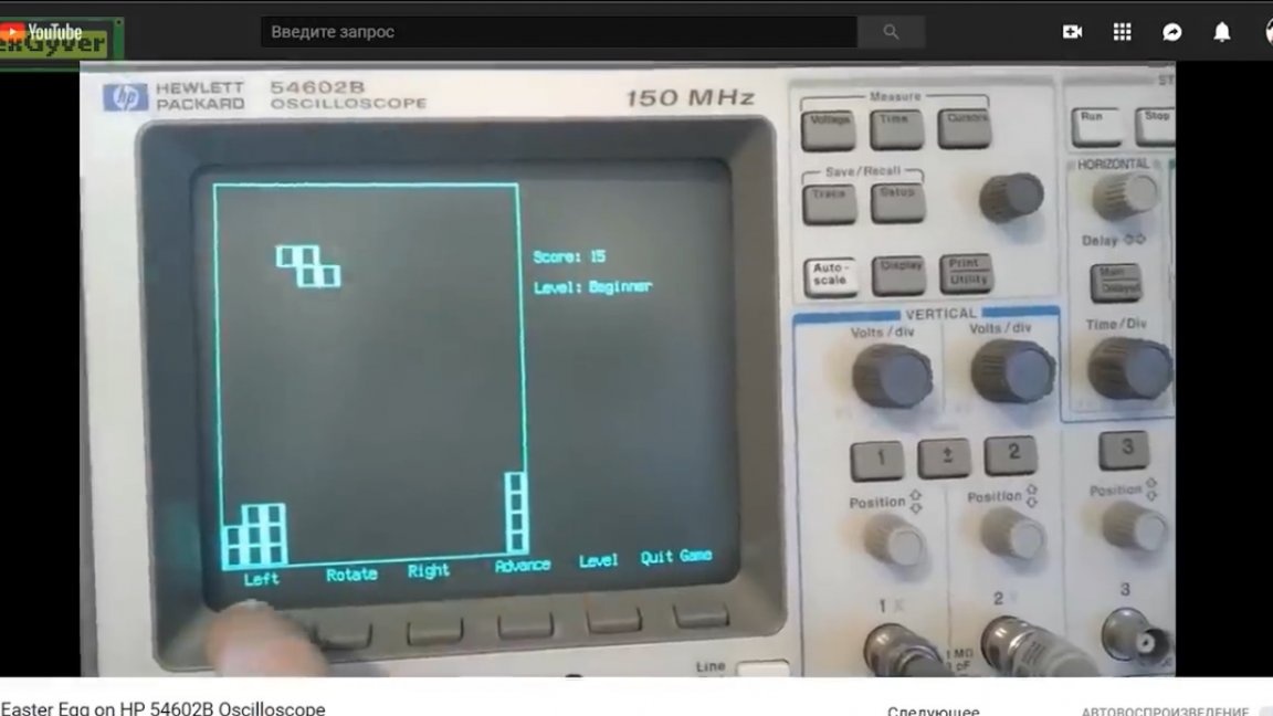
The original Pascal version appeared on June 6, 1984. Since then, Tetris has come a long way and has been ported to all platforms on which it is generally possible to play games, as well as to devices not intended for games at all, for example, such as an engineering calculator, oscilloscope and, you will not believe, a soldering iron.

By the number of commercial versions sold, Tetris is superior to any other game in the history of mankind. For just one Game Boy, 35 million copies were sold, not to mention the portable Brick Game, which almost all had at one time.
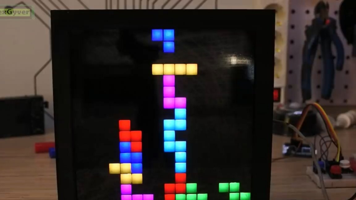
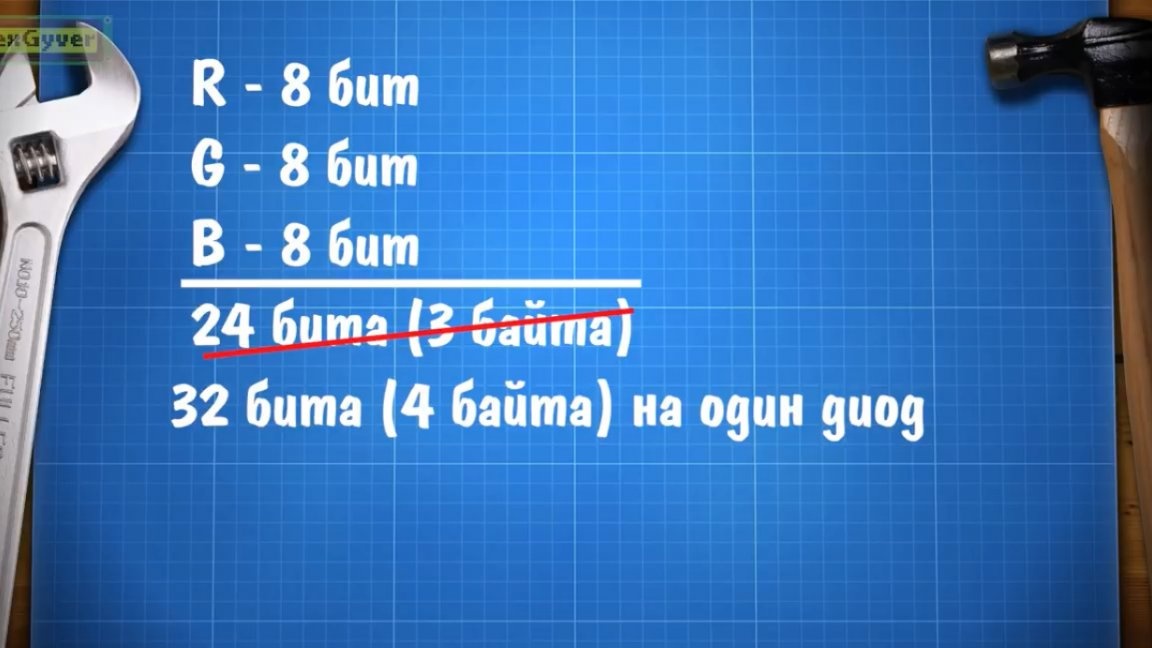
We will begin the implementation of tetris on arduino and a color matrix with the analysis of “crutches”. The matrix consists of three-color address LEDs. The problem with this type of matrix is that it is too cool. The color of each pixel is encoded with 24 bits, that is, 8 bits for each component: red, green and blue. There is no such type of data on arduino, there is the following - 32 bits.
The colors of all LEDs should be stored in RAM, as we will change them. And that, for a 16 by 16 matrix, we have exactly 1 KB of occupied dynamic memory, and arduino nano has only 2 of them.
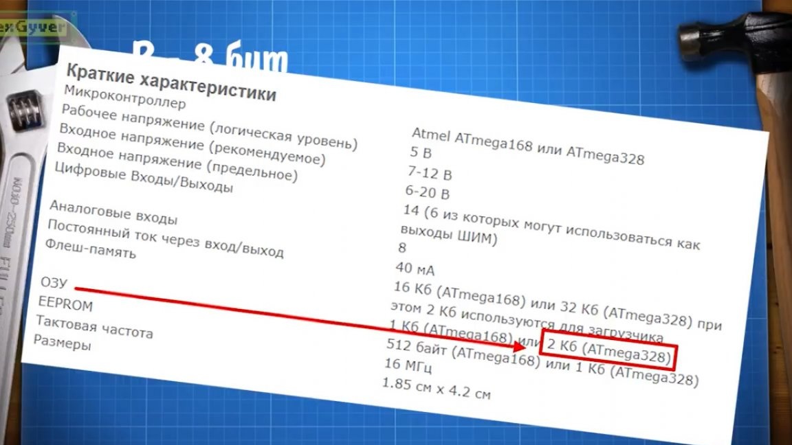
Add a few more libraries and start writing code, the memory will end. The author basically does not use, for example, arduino mega, where there is more memory. The goal is to make the game on arduino nano, using simple, standard and well-known tools, but at the same time non-standard approaches and “crutches” and with their help achieve the most optimal code.
The first “crutch” will be the refusal to separately store in the memory the positions of the figures and in general everything that is happening on the screen.We need to store the coordinates of the points of the feeding figure and the coordinates of the points of the already dropped figures, that is, as a maximum, we need another 1 array, two-dimensional 16 by 16, and this is as much as 256 bytes.
You and I already have an array of colors for all pixels, let's use it. Indeed, in addition to the fact that we can put a colored dot on the matrix, we can measure the light of an existing point so that we work with colors.
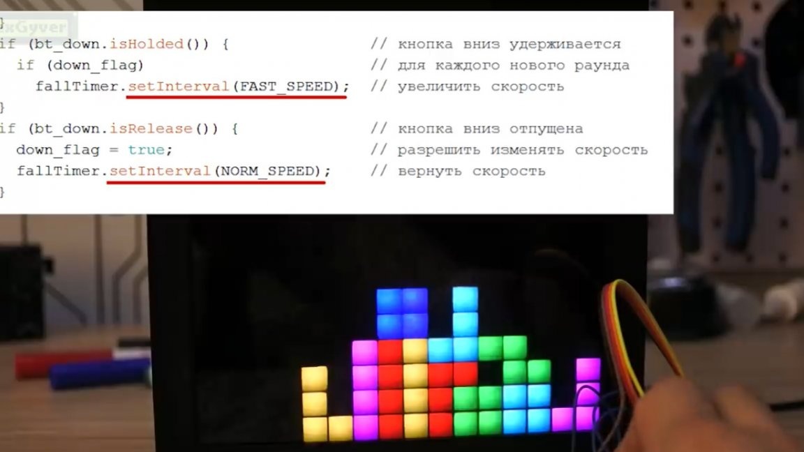
Tetris begins with a falling block, which is controlled by buttons and has 2 coordinates in the matrix coordinate system. It is very simple, we build a timer, according to which the block will fall. This is the author’s library, you can read on the site.
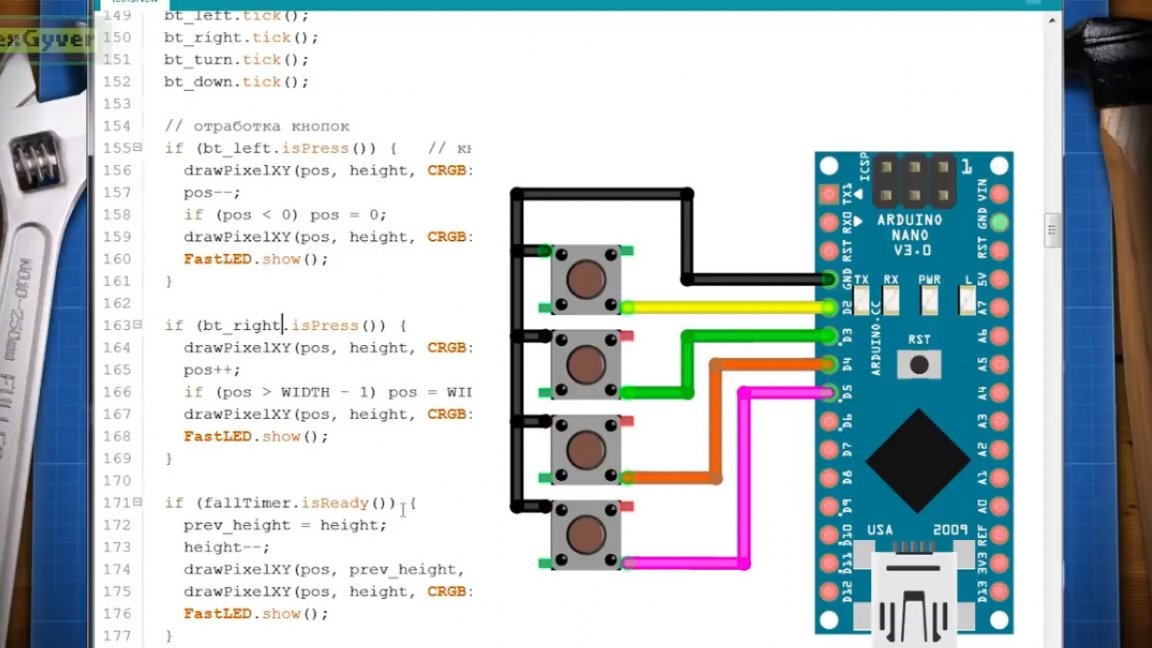
To process buttons, the author also uses his library. The connection scheme of the buttons is ridiculously simple: 4 buttons, 8 wires.
Each step of the timer, we draw a point a pixel below the old one, and draw the old point in black, that is, turn off the LED. By clicking on the button, we do the same, but with a horizontal coordinate. Well, for decency, we will limit the size of the matrix so that the point does not go beyond the field.
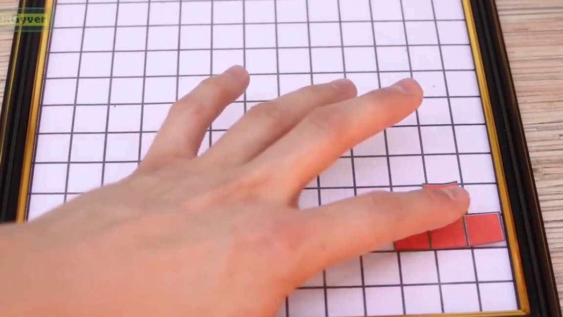
See, nothing complicated. But this is not for long because the time has come to draw figures. We will work as follows: we will keep the reference to the supply point, which we have already written, we will call it the main point or the main block. The main block moves in the matrix coordinate system, we have already done this. All figures of Tetris consist of 4 blocks, which is why, by the way, it is called Tetris.

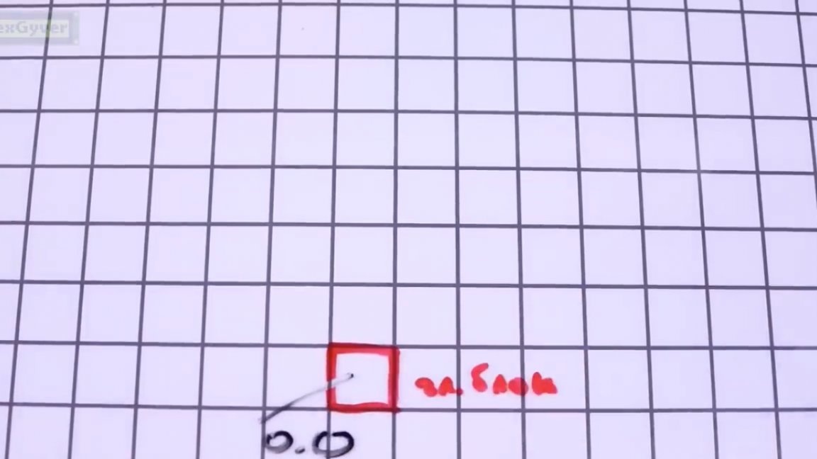
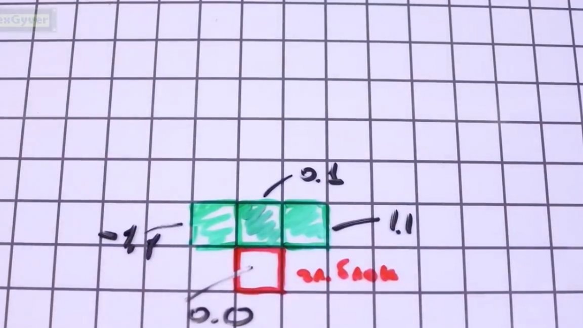
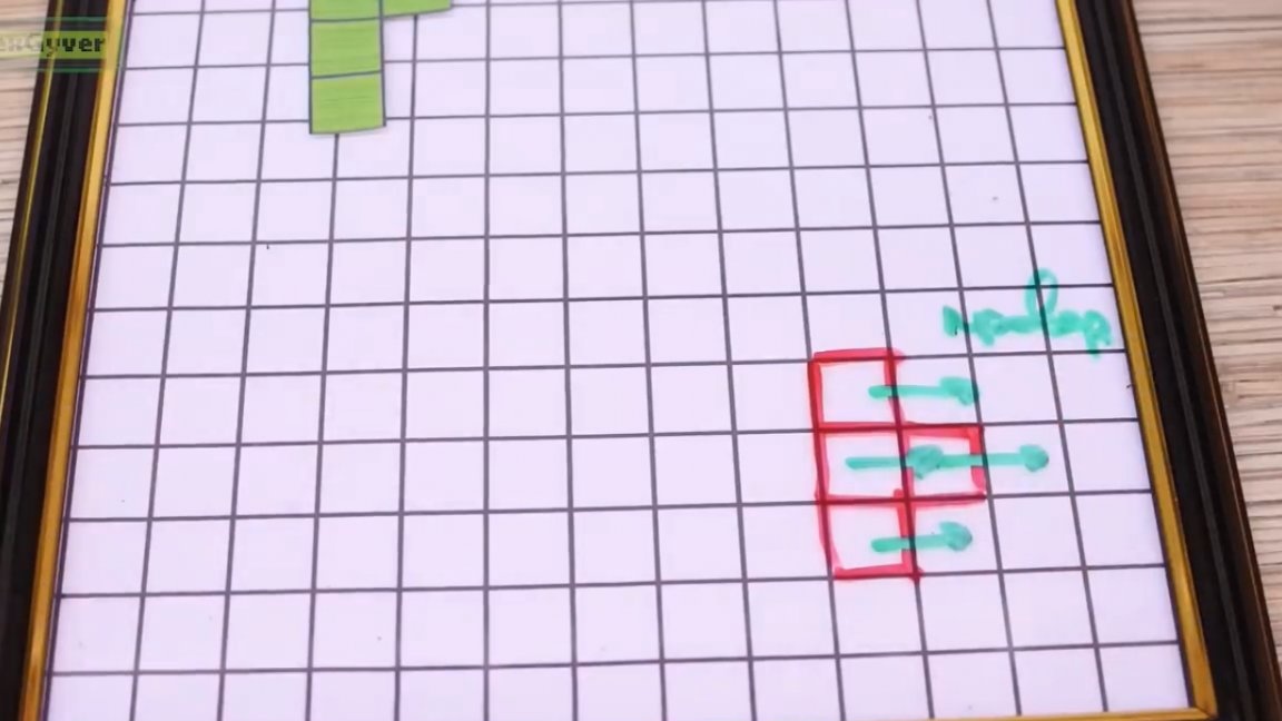
Accordingly, it remains for us to finish adding 3 more blocks to the main block. Let's write their coordinates in the coordinate system of the main block, so that the main block is always below. It’s very simple, take the figure of the inverted letter T. The main block from the bottom to the center has coordinates 0.0 in its coordinate system.
The upper block is 0.1, the right is 1.1 and the left is -1.1.
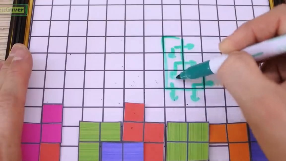
Take the letter G. The lower block is 0.0, the next 0.1, the next 0.2, and the edge of the letter 1.2.
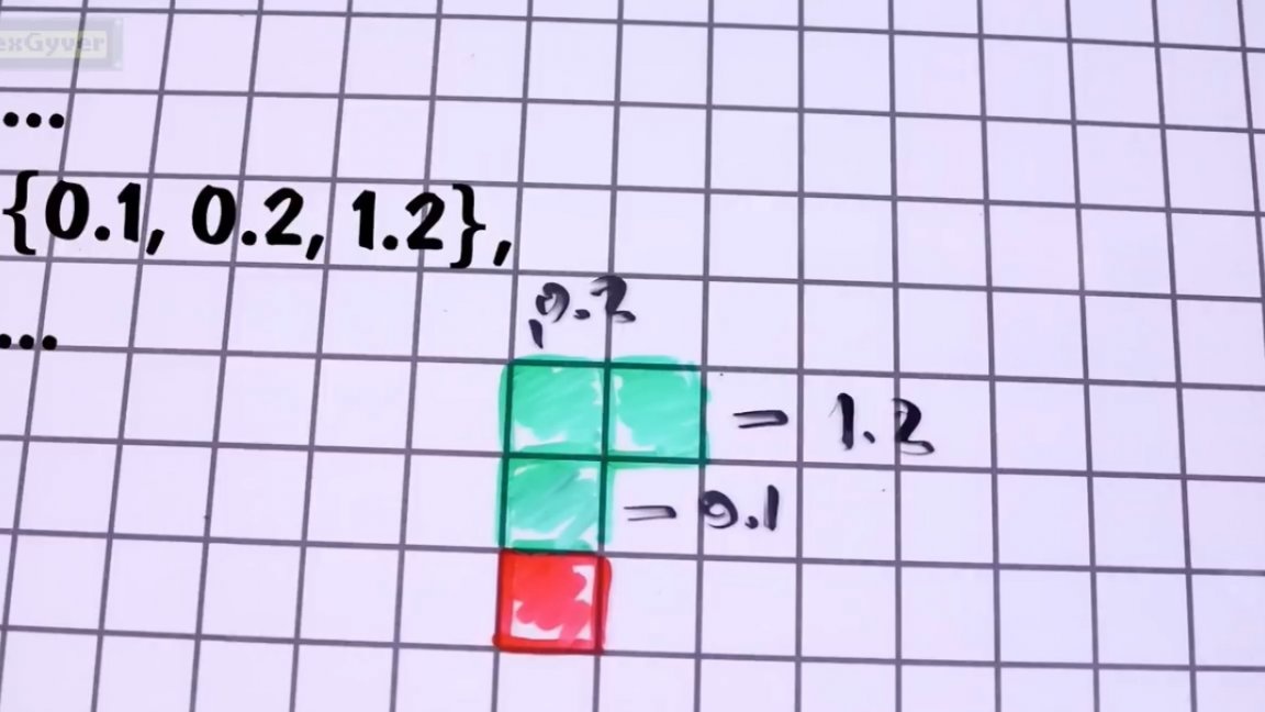
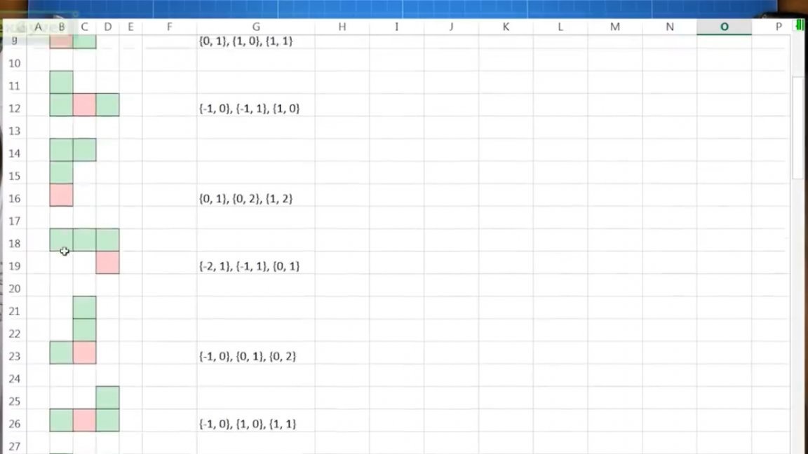
We write these coordination into the array in the following form: {0.1, 0.2, 1.2} and drop the array into flash memory so as not to waste dynamic memory. As for the rotation of the figures. It is impossible to rotate the figures. It is corny it is very difficult to explain to the microcontroller how to do this. To do this, you need to set the center of rotation, somehow decompose the figure into parts and look for new coordinates for each part, taking into account strong pixelation, which will obviously lead to errors and it will turn out nonsense. The problem is solved very simply, we will keep in memory all 4 positions for all figures and all.
Actually, now it remains to randomly select the figure number and draw it around the falling block. Here, for all 3 remaining blocks, we take the coordinates from the flash memory, translate them into the global coordinates of the matrix, and turn on the LEDs. By the way, the color is also chosen randomly from the 6 most simple and bright colors of the rgb space. The angle of rotation of the figure at the beginning of the round is also set randomly, and when you press the button up, just take the next set of coordinates to draw and rotate it clockwise. Moving a shape works all the same. First, we erase the figure at the previous position, that is, draw it in black, then in the new position draw the current color of the figure. When turning, again, we erase the old position and just draw a new one.
Firmware can be downloaded at. We will analyze only the essence. Let's start by checking the left and right walls and the bottom. Everything is very simple with the bottom, we look at each step of the fall, has the base unit reached a height of 0, this is not difficult, but every time we press the control button we need to see if the extreme point of the figure touched the side walls of the matrix.
If touched, do not move the figure. The same goes for the rotation of the figures. For example, if the new position of the figure extends beyond the walls, then the rotation is prohibited, and since all the figures we have are of different shapes, then the extreme blocks for them are all different. It would be possible to paint individual extreme blocks for each figure in order to simplify the work of the microcontroller, but let it be considered that they invented it for this.
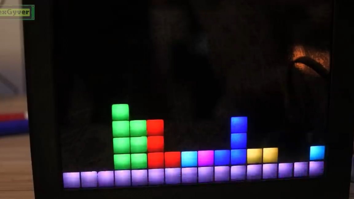
Everything is very simple. But the next task is much more interesting. We need to check for collisions with blocks already lying below.If we had an array that contained the state of all the cells in the field, it would be easier, but we will use an array of colors for the pixels of the tape, so we will have the coolest “crutch”. What is the actual problem. Everything seems to be simple, a green figure will fall, and every step of the fall, every shift to the side and every attempt to turn should check whether the figure in the new position rests on the already lying figures. If for all blocks the surrounding color is equal to black or equal to the color of the figure, then we allow movement in the desired direction. This will work until the shape below us is the same color as the falling shape. That's actually the “crutch”: we will repaint the fallen shape in a different color. Repain invisibly to the eye, but noticeable to the program. All you need to do is slightly increase the brightness of the current color of the shape and that’s all.
The figure fell on the bottom or another figure, its brightness did not increase noticeably, and in the new round the falling figures will no longer confuse its color with their own, they will fall on it and just as fixed, slightly adding brightness.
By the way, when you press the button down, the figure rushes down at a high speed and takes its place.
Our Tetris is left with the final touch, namely checking and clearing the filled levels horizontally. Everything is simple here. After fixing the figure in the current round, we move along the lines and compare the colors of the pixels with black. If there is not a single black pixel in the entire line, then we will clear the entire line.
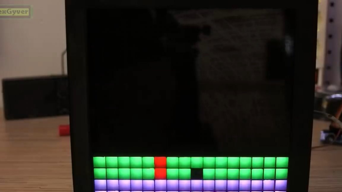
The detected lines are filled with white, then the brightness gradually drops to zero and the animation is obtained. Further, all pixels, starting from the first filled line to the top, are shifted down by and the number of lines that have been cleared. This process is repeated until there are no completed levels. We also check if we have reached the top, which means losing. In this case, an account equal to the number of cleared levels is displayed.
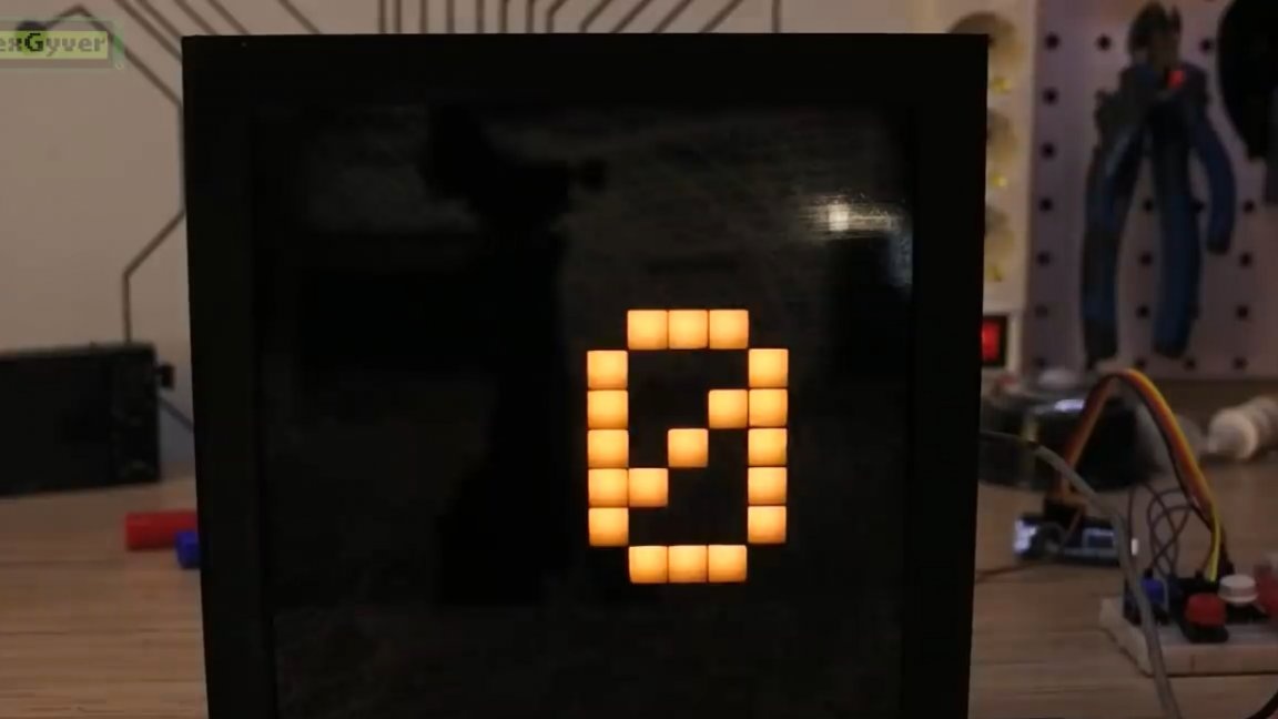
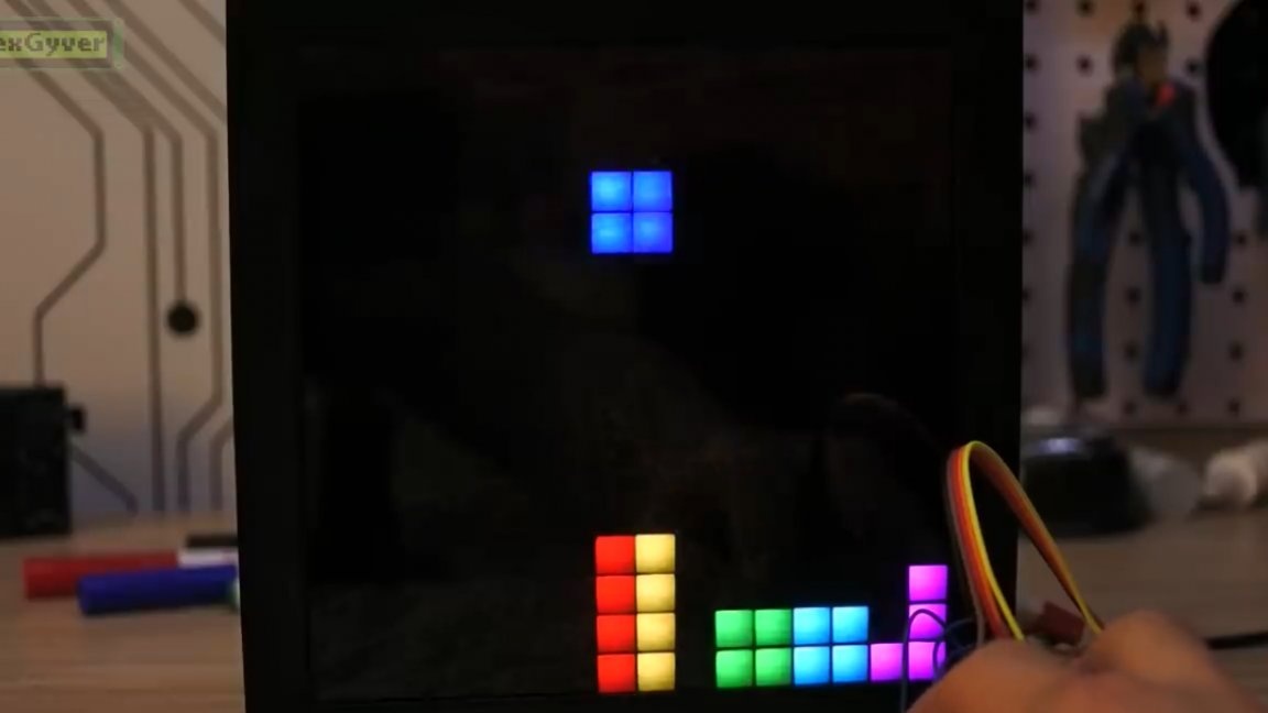
The account is displayed in numbers, which are stored in memory as a set of ones and zeros, according to which the LEDs are then turned on or off. This is what Tetris written in the address matrix looks like. Thank you for attention. See you soon!
Video: