

They don’t like boring, but we all are. Past homemademade soulmate, I could not go. Look how unusual.
It is believed that logic elements containing inverters - AND-NOT, OR-NOT and exclusive OR-NOT - cannot be performed on diodes and resistors alone. But the author of Hackaday under the very cool nickname Dr. Cockroach (imagine a cockroach with a phonendoscope - funny?) Showed a little tediousness and concluded that the LED is a kind of diode, and the photoresistor is a kind of resistor. Yeah, it’s still possible!
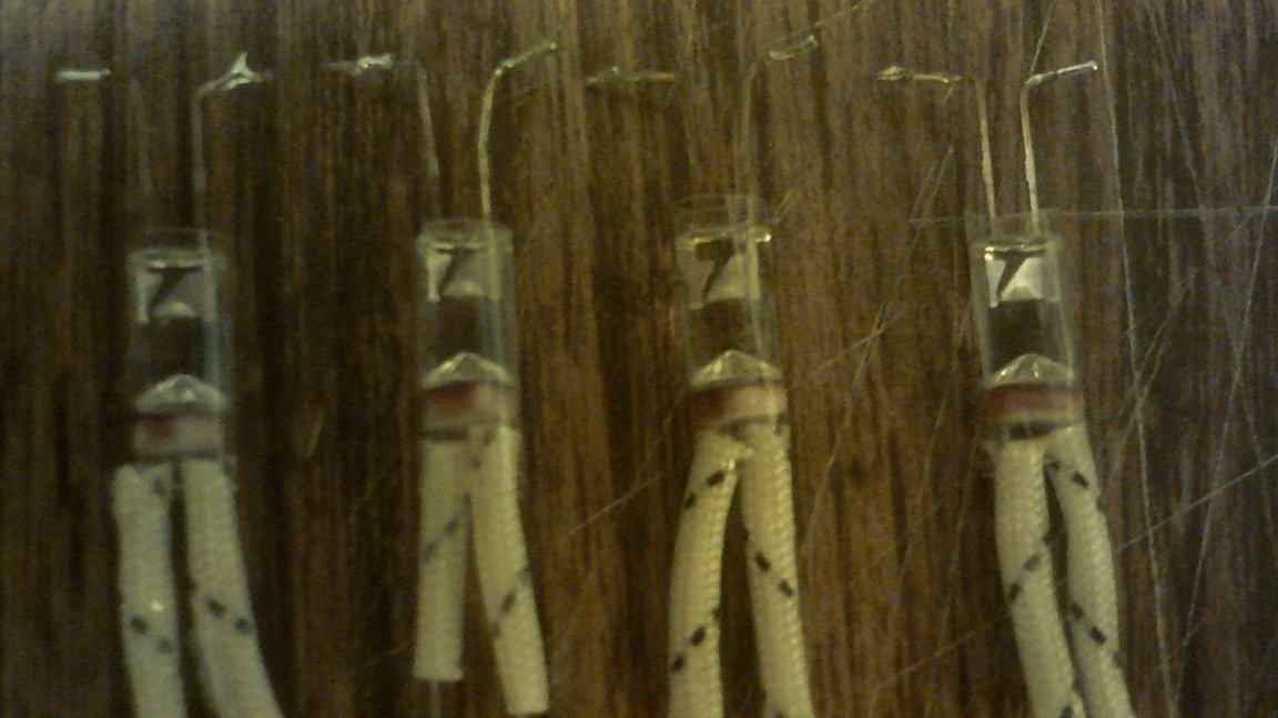
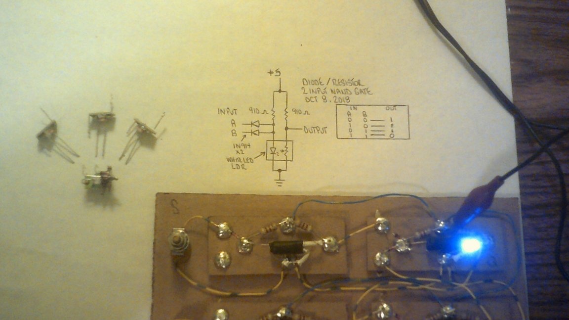
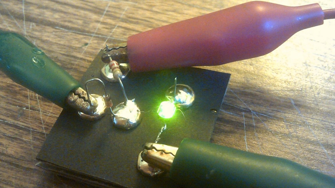
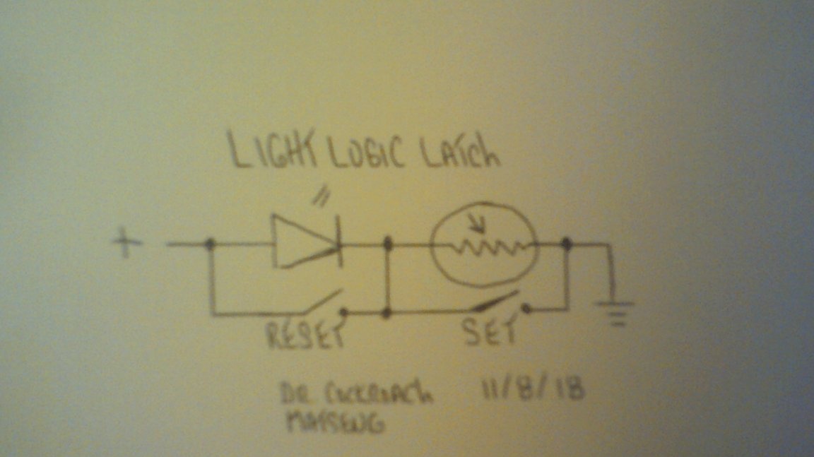
First, he made an optocoupler from an LED and a photoresistor, and then included it in such a circuit:
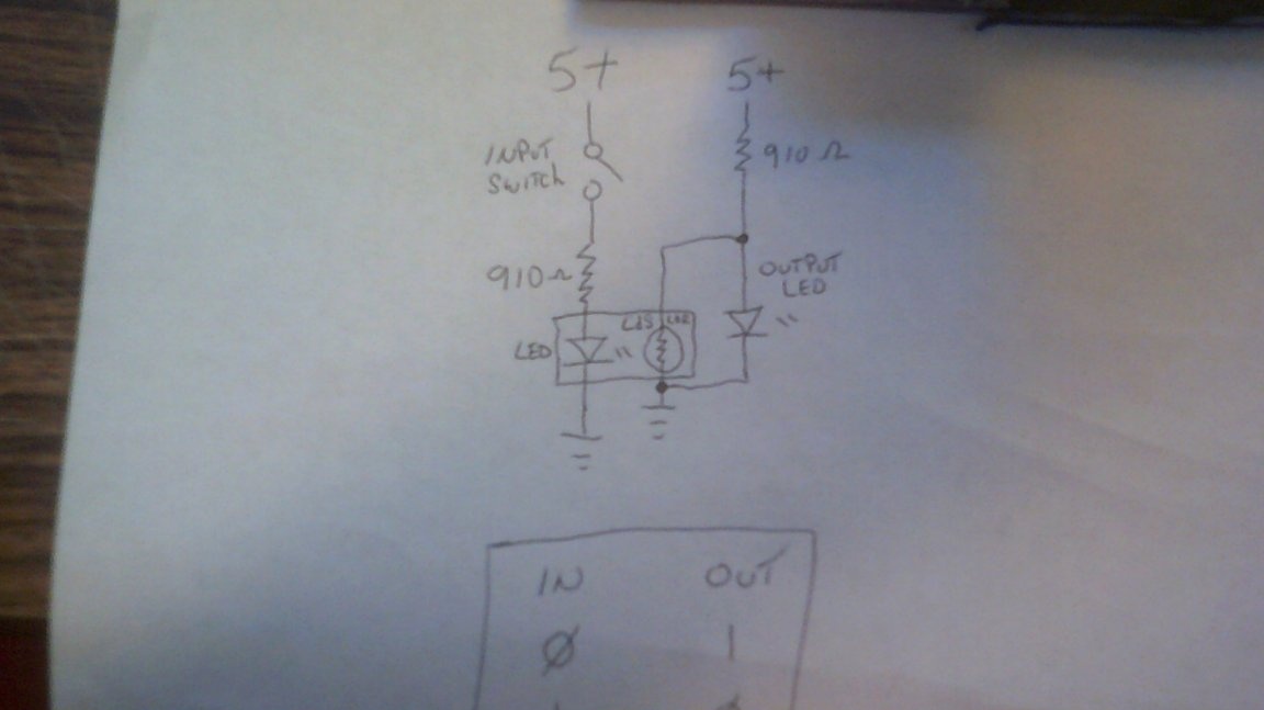
The indicator LED - one that is not part of the optocoupler, but is visible to the user - he connected not in series with the photoresistor, but in parallel with it. When the optocoupler LED is on, the resistance of the photoresistor becomes less than the resistance of the resistor through which the indicator LED is powered. What happens is scientifically called shunting. The indicator LED turns off. And if you turn off the optocoupler's LED, the indicator, on the contrary, will turn on, since the bypass will stop. So, we got an inverter on some diodes and resistors. The first logical element for bores earned!
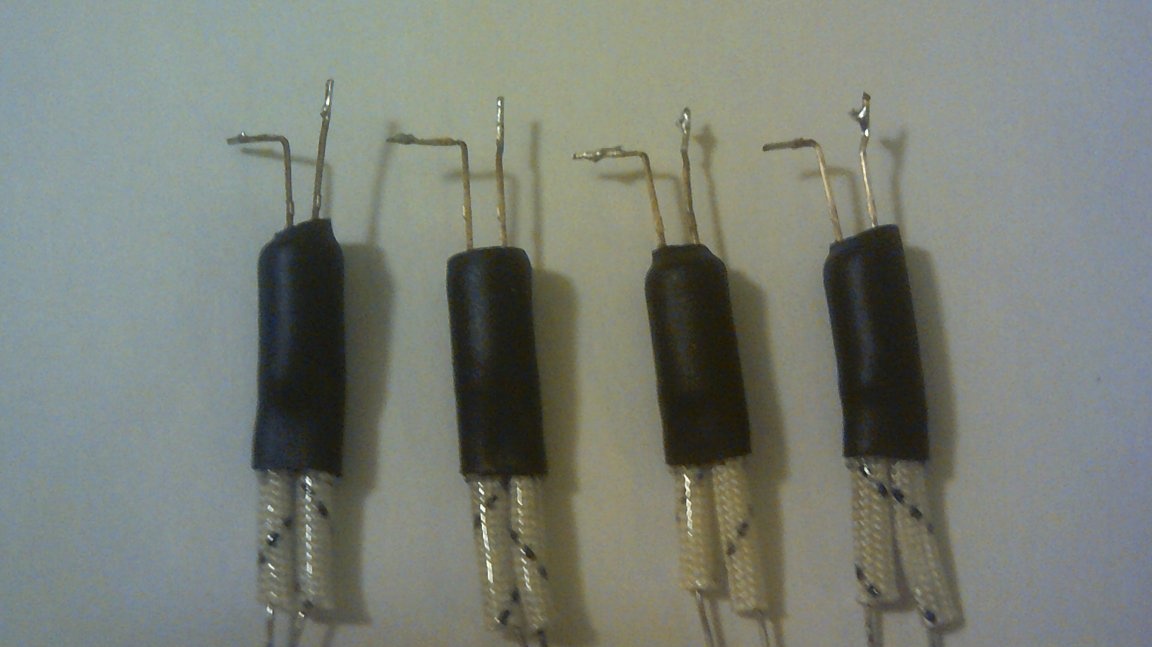
But the optocoupler, of course, was cumbersome. Now Dr. Cockroach will fix it.
Now more compact. Only light will penetrate from the outside. In general, it’s not just that people invented shrinkage. She will come in handy!
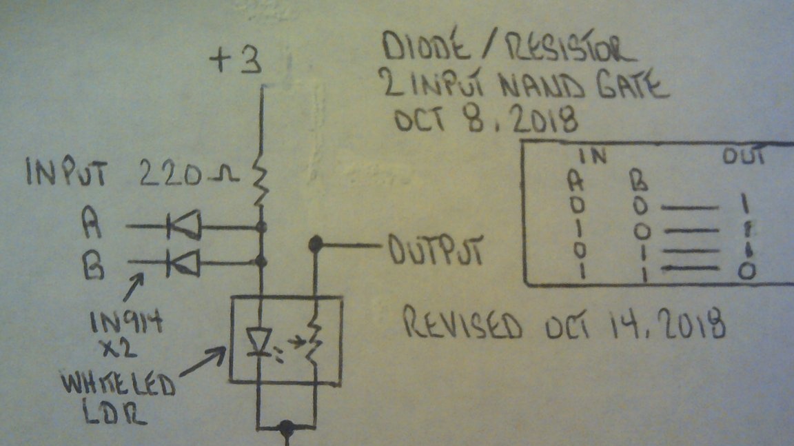
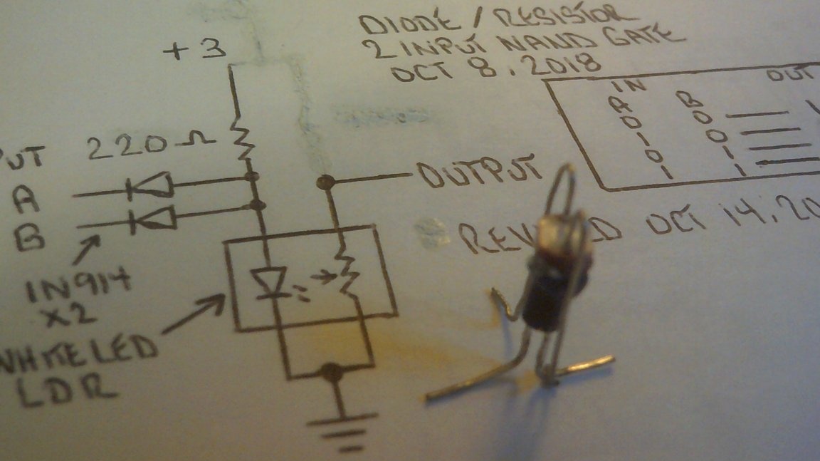
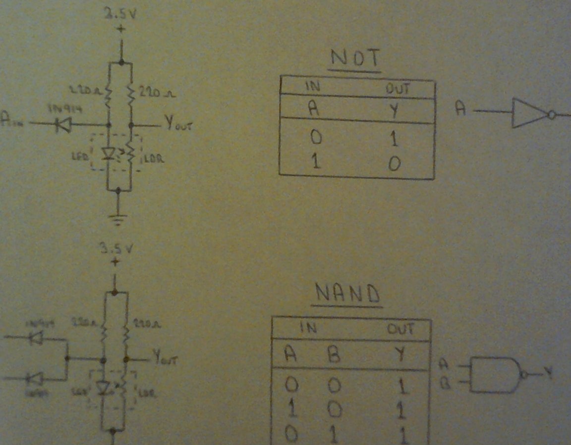
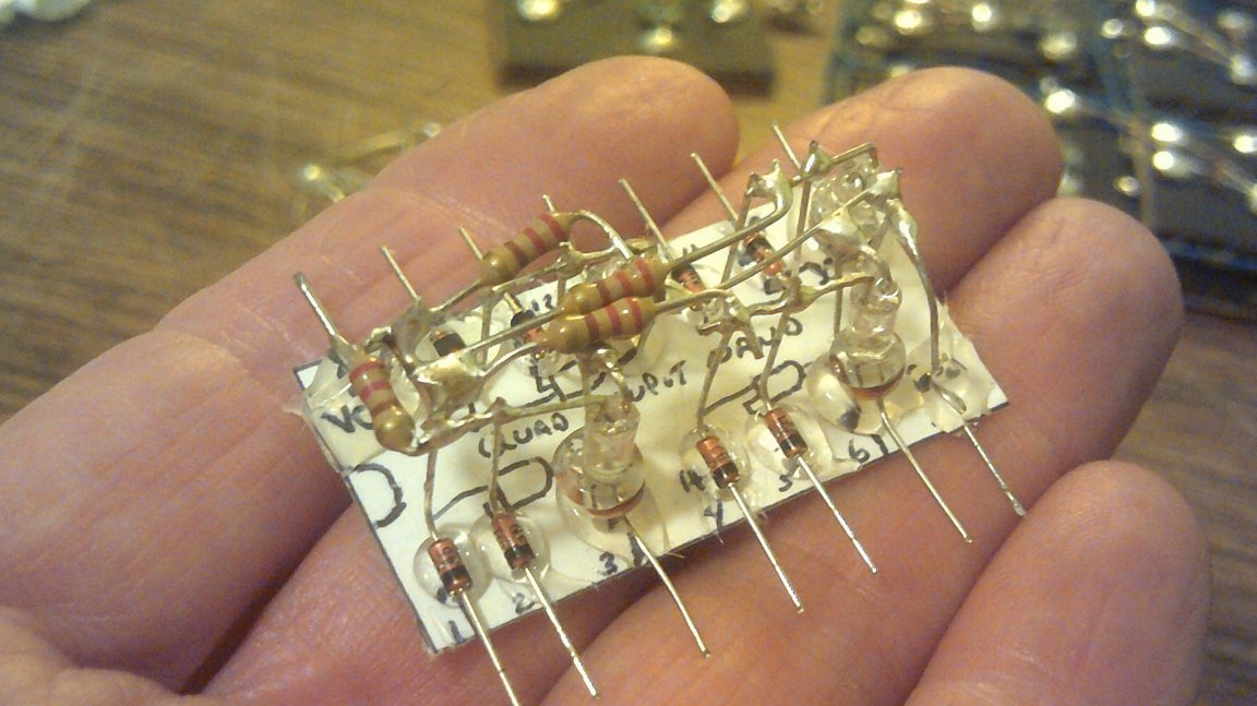
Instead of an indicator LED, the LED of another optocoupler can be connected to the inverter output, that is, complex circuits can be composed of such logic elements. But on some inverters you will not go far. Realizing this, the master added the usual, non-luminous diodes and made a nice element NAND:
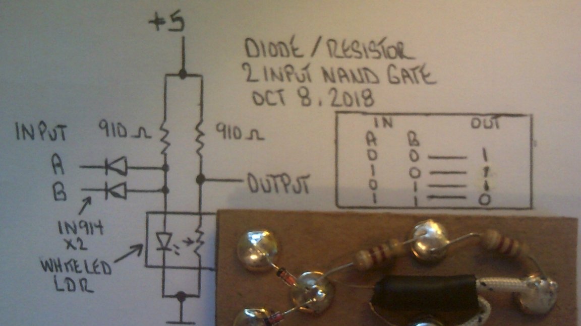
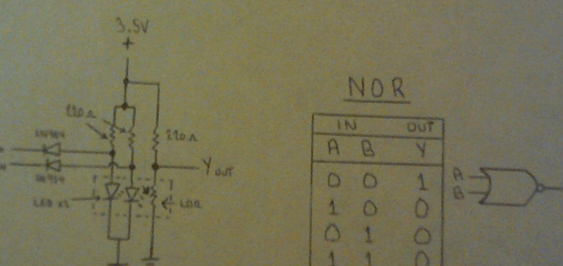
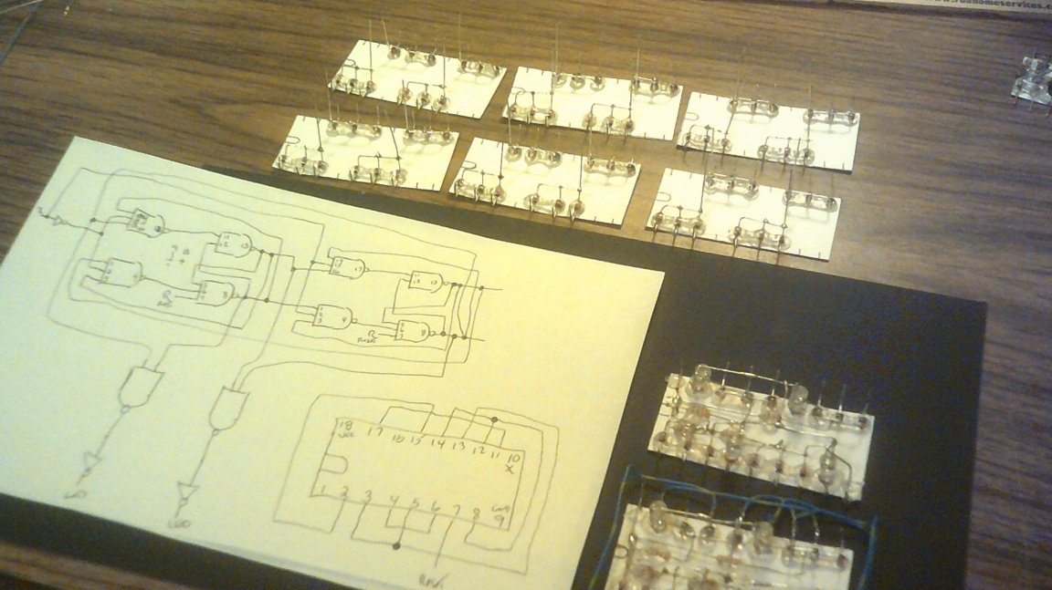
If in this circuit the usual diodes are reversed and the left resistor is excluded, an OR-NOT element is obtained. Now that the elements themselves are developed, the wizard thinks about where to apply them, and does such a thing:
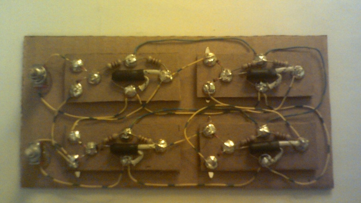
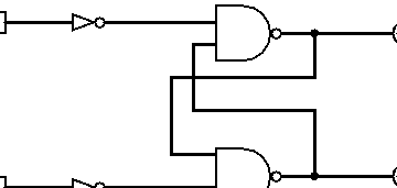
This is an RS trigger. Two AND-NOT elements in it are used as inverters (both inputs are connected), the other two are the same for their intended purpose. Take a look at the diagram:
Dr. Cockroach checks her:
It works as befits an RS trigger.
Having disassembled several nightlights, Dr. Cockroach found in each of them a photoresistor and a small board with an SMD LED.He also made optocouplers from them, and then thought: why for each logic element do a rather large board if resistors and ordinary diodes can be placed very compactly using surround mounting? Compare the new logic elements with the old ones - the difference in dimensions is significant!
The findings are as follows:
The tests are in full swing, and judging by the absence of screams and punching the table, everything works as intended:
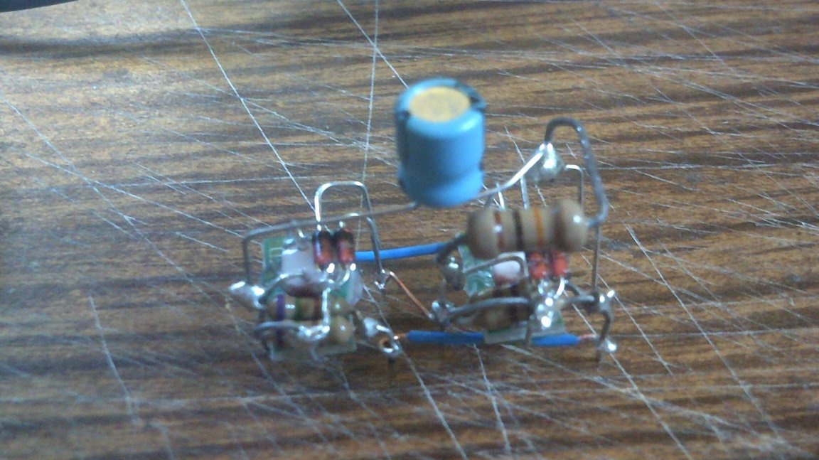
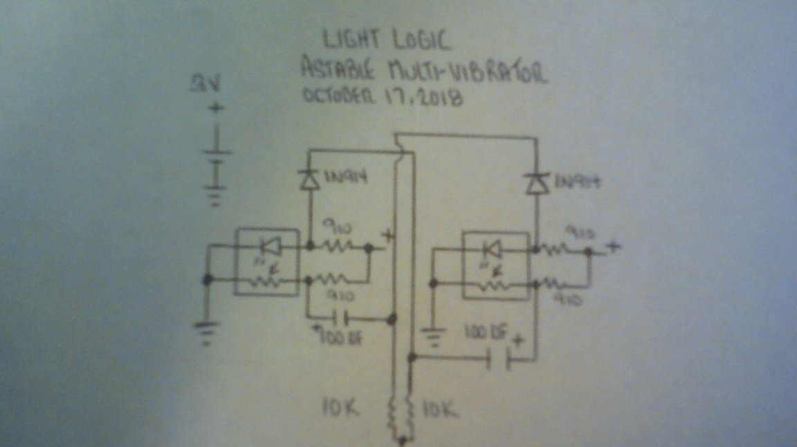
Not only triggers, but also multivibrators are built on ordinary logical elements. On the "boring", it turns out, too, is possible. And on non-SMD-shnyh:
And on SMD-shnyh:
I remember there was a fantastic film about robots multiplying by disassembling various pieces of iron and assembling their own kind from their parts. Very similar to one of them:
Guided by the electrical and logical circuits, you can also repeat the wizard experiment:
Please note that on the first of the Dr. Cockroach did not show the indicator LEDs and resistor for them.
Then the master looked at the circuit of the AND-NOT element again and realized: a pull-up resistor at the output is not necessary, because it is at the input of the next same element. Of course, if the next element is OR-NOT, where there is no pull-up resistor just at the input, nothing will work. But the elements OR-NOT "Doctor Cockroach" decided not to use it anymore, because some loss of voltage of a logical level occurs in them. OR elements can always be made from inverters and NAND elements, which are now arranged like this:
This is how the circuit of the multivibrator and the NAND element works:
And the master decided: instead of waving him at the whole JK-trigger?
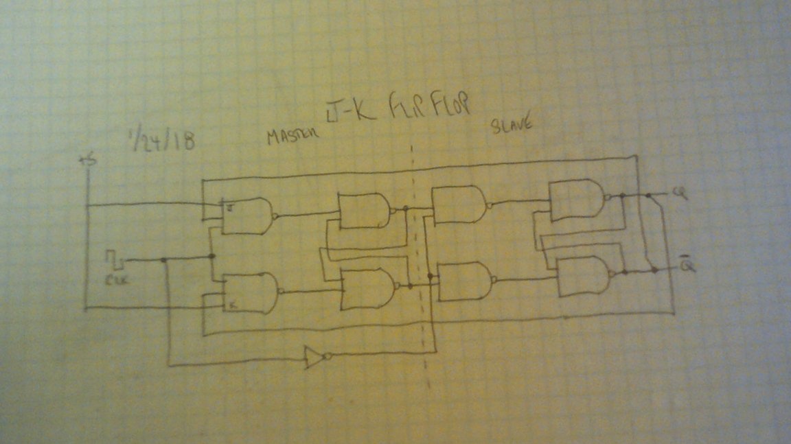
And to make it more brutal and clearer, Dr. Cockroach from logic gates, albeit with SMD-optic couplers, but on risers:
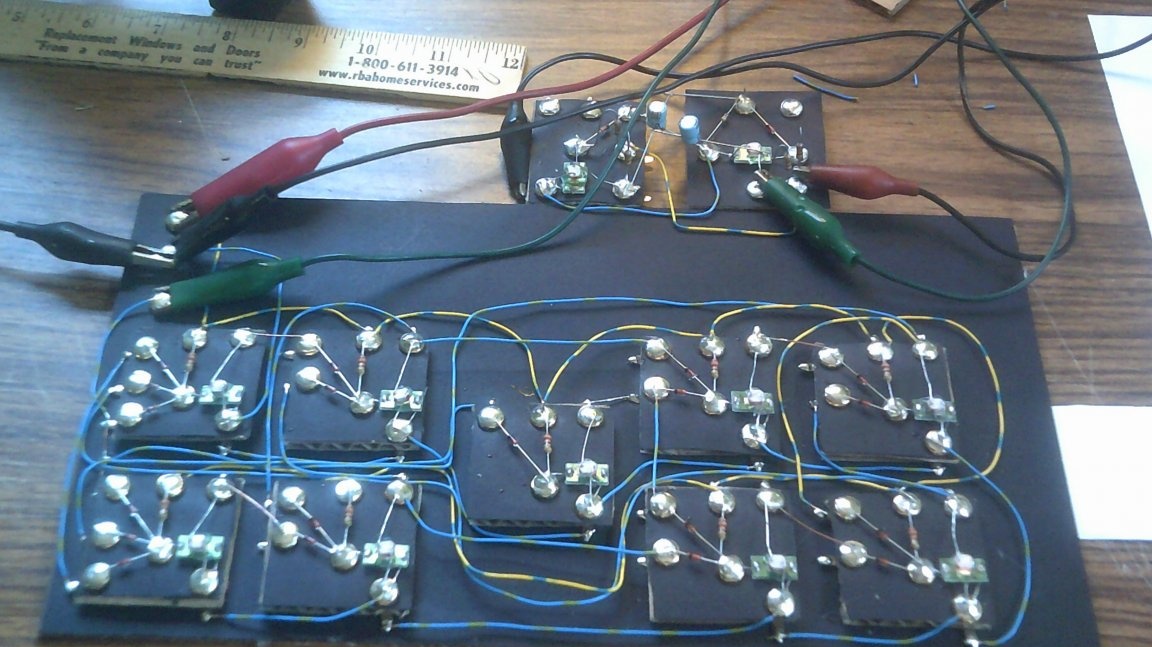
So it works when clocked with a multivibrator. The circuit is very critical to the supply voltage.
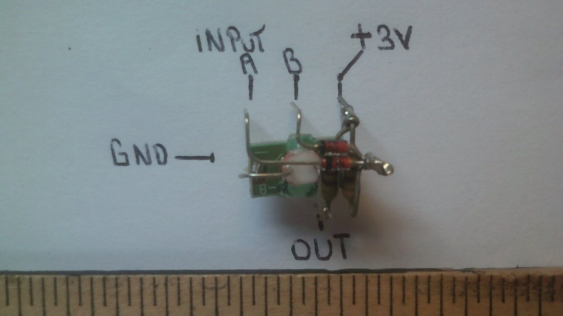
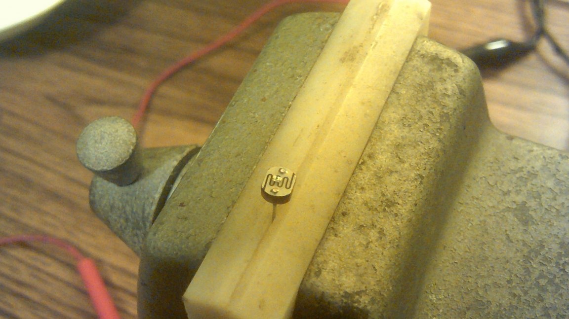
Well, on the contrary, he made the element in a non-SMD version miniature, using volumetric installation, and gave it a vertical shape to look like a transistor:
By its behavior, such an optocoupler is also similar to a transistor, and not a field one, but a bipolar one. For it is controlled by current.
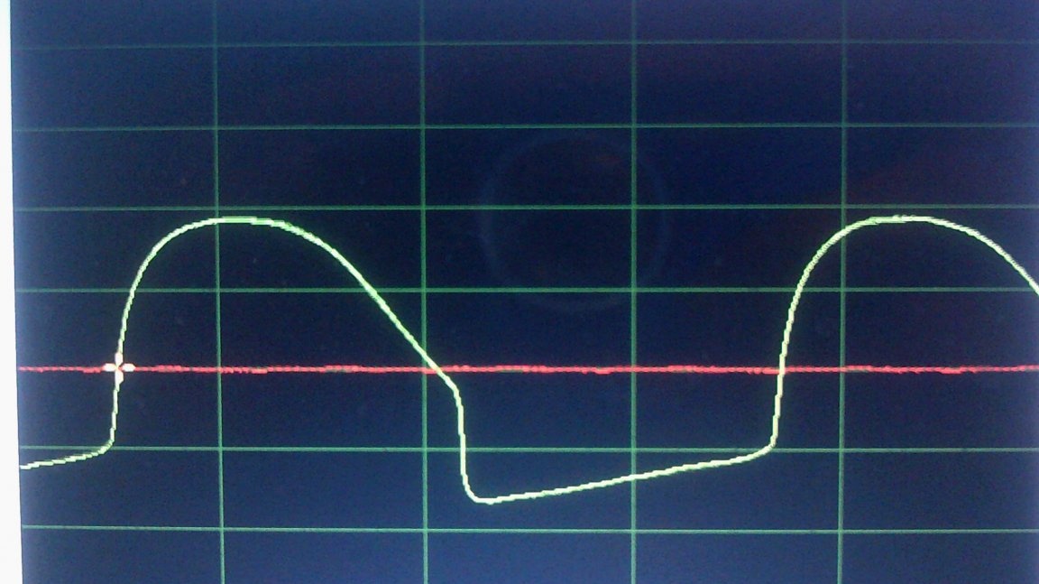
These logic elements operate at low frequencies, so it is convenient to monitor their work using a software oscilloscope on a computer or smartphone. Dr. For starters, Cockroach tried to theoretically calculate the waveform at the outputs of the multivibrator at a frequency of 43 Hz and the exact selection of the supply voltage:
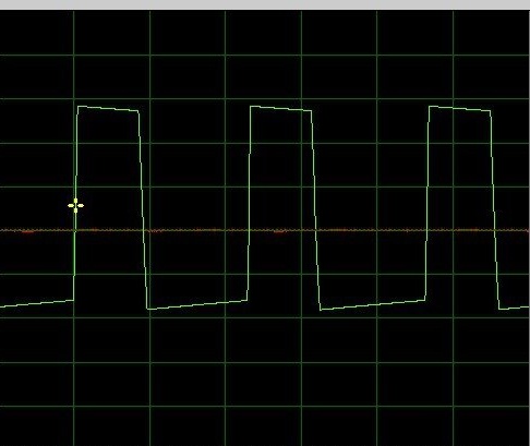
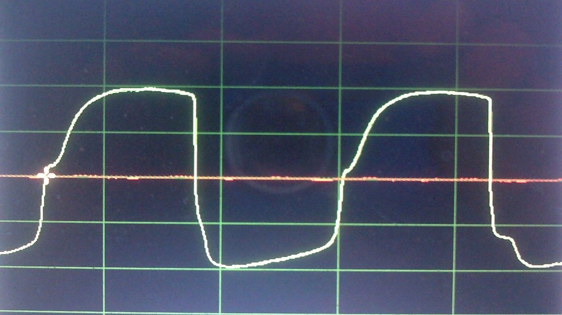
Real signal at 19.8 Hz:
He, after inverting:
But what will happen if the frequency is increased to 42.2 Hz:
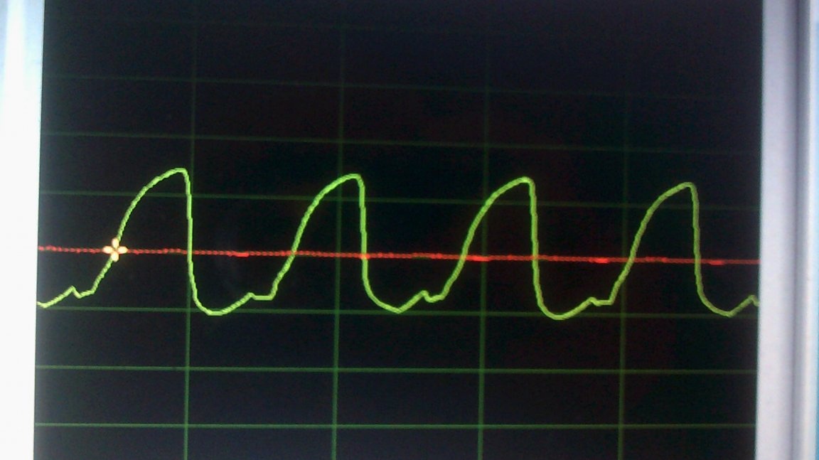
"Dr. Cockroach" came to the conclusion that the parasitic capacitances in the photoresistor distort the waveform.
The master is experimenting with LEDs of size 0402. They are so small that any of them, compared to the photoresistor, is tiny:
And it works:
But since the logical element is not assembled again by volumetric editing ...
The master attached another multivibrator to the JK trigger and admires the result:
And now he shares the circuits of elements NOT, AND-NOT and OR-NOT, and in the third optocoupler contains two LEDs. It is not clear, however, how this is consistent with the fact that earlier he wanted to refuse OR NOT to refuse at all.
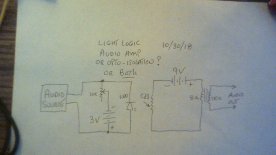
Dr. Cockroach decided to try making a linear amplifier on an optocoupler - not all the same, to be limited to logical elements. It turned out exactly the amplifier - with it, at the same amplitude of the input signal, the sound is louder than without it. Just never do this - if the circuit has a constant source, the signal source must be connected not directly, but through a capacitor.
And this is a microcircuit, more precisely, a microassembly with four NAND elements, just like in our beloved K155LA3!
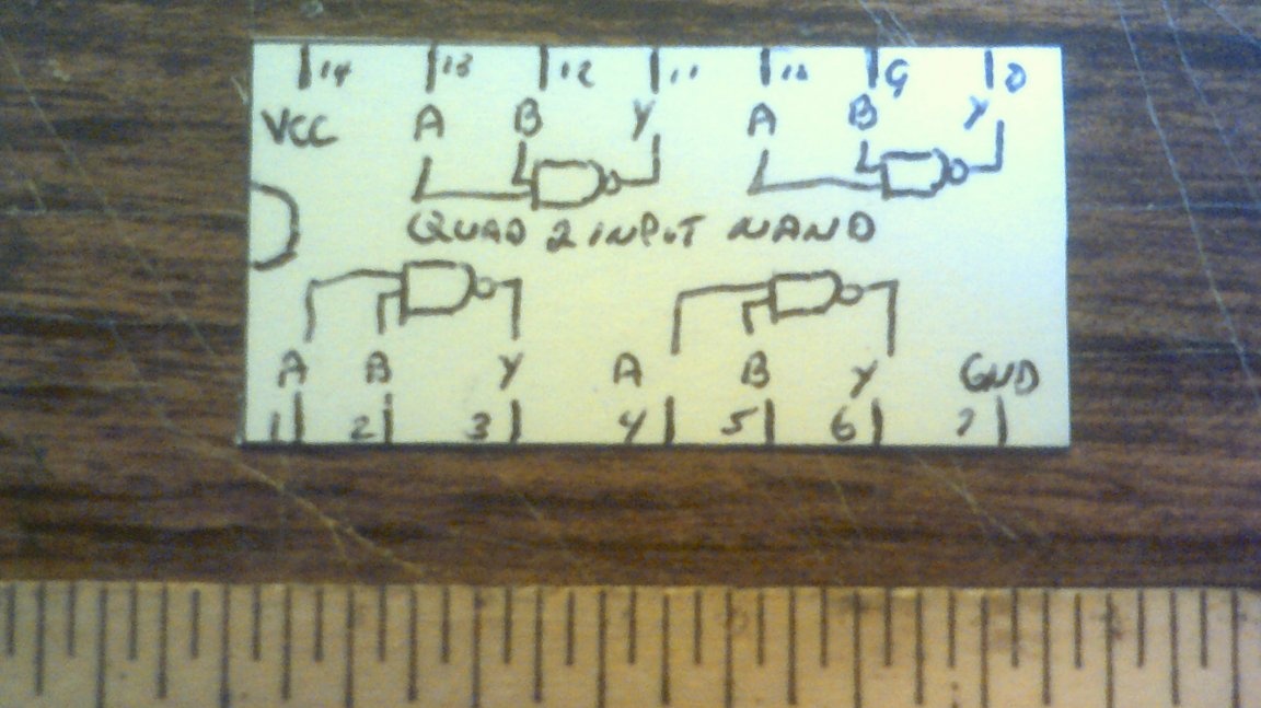
Where there is an analogue of K155LA3, there is also a D-trigger - it requires just four logical elements AND NOT. Like the prototype chip, a home-made microassembly can be turned into such a trigger by adding only one wire.
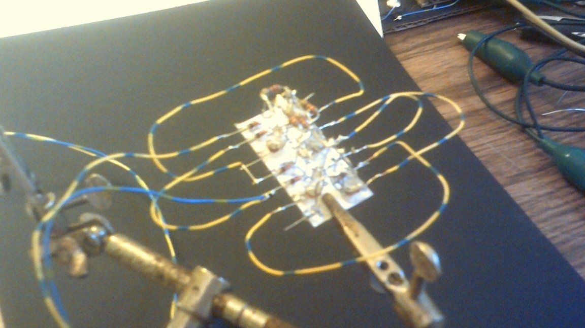
To control the trigger, the master built an unpretentious, but perfectly working remote. This time, of course, everything worked out again:
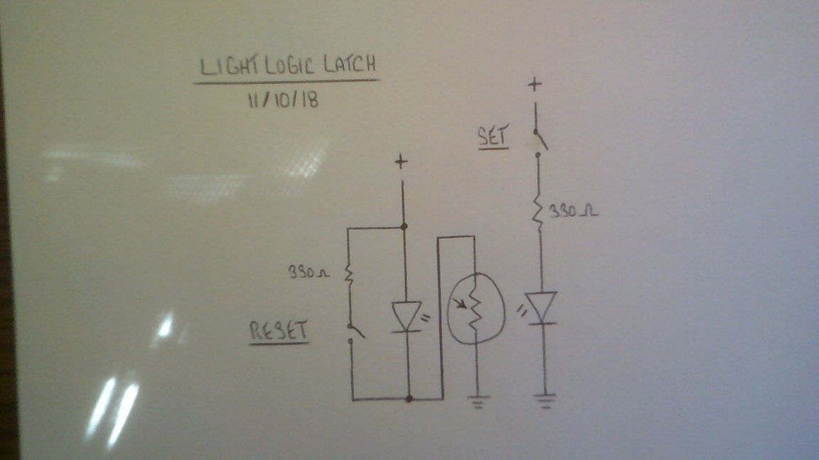
The RS-trigger can be greatly simplified if you do not make it from logic elements, but apply the principle of a self-locking relay familiar to every electrician.Only slightly modified, so you can’t press both buttons at once - short circuit the power source:
Another trigger, a little more complex, is free from this drawback. In it again two LEDs are directed at the same photoresistor at once:
In order for the trigger to have an output, Dr. Tarakan complicated the circuit a little more (where now, on the contrary, one LED shines on two photoresistors at once) and added an inverter:
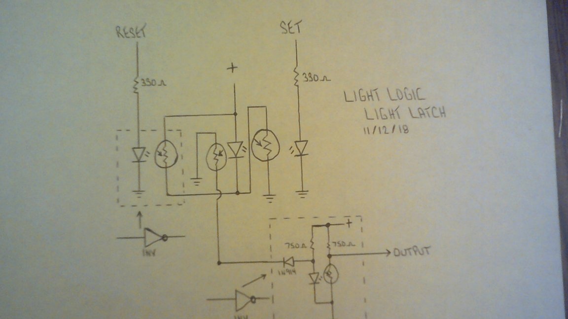
Everything works again:
To make a single-shot with an unregulated output pulse, Dr. Cockroach provides the input signal AND directly to one input of the element, and the same signal to the other, but passed through a chain of three inverters. That, in general, is equivalent to one inverter, only the delay is longer:
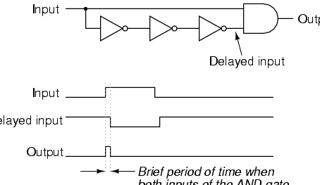
Well, long pulses are input, short ones are output. What you need!
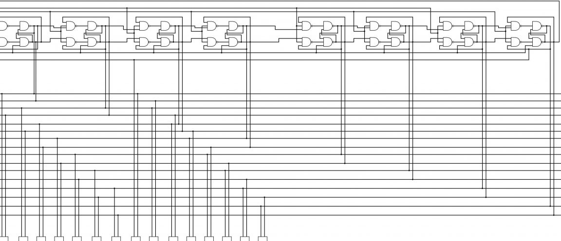
Well, in front of the master - a whole counter of triggers, but he is not ready yet:
I hope that now the reader will be a little more loyal to bores. One of which proved that inverting logic elements on the same diodes and resistors are possible if the LED is considered a ford, and the photoresistor is a resistor. And he did so many interesting things. And he’ll definitely get this counter.
In general, being a bore is great!