
The author of Hackaday, nicknamed Yann Guidon, built a huge binary seven-segment decoder on relays and diodes, replacing ... just one tiny chip like K514ID1. Only a microcircuit is boring, and to see how it works, you need to break it and place the crystal under a microscope. And here you can see where everything is located, what function it performs, and what will change if the circuit is modified in one way or another. And most importantly - it mysteriously clicks every time you switch.
Homemade powered by a bipolar 3.3-volt power supply. For each of the poles, it can consume up to 0.45 amperes, depending on which hexadecimal digit it shows. The scheme includes: ten RES-15 relays, one seven-segment IV9 glow indicator, fifty-nine D9K germanium diodes. The input resistance of each of the inputs of the decoder is equal to the resistance of the relay winding. The device is open hardware licensed under Creative Commons BY-SA 4.0. The assembly of the circuit was completed in August 2018.
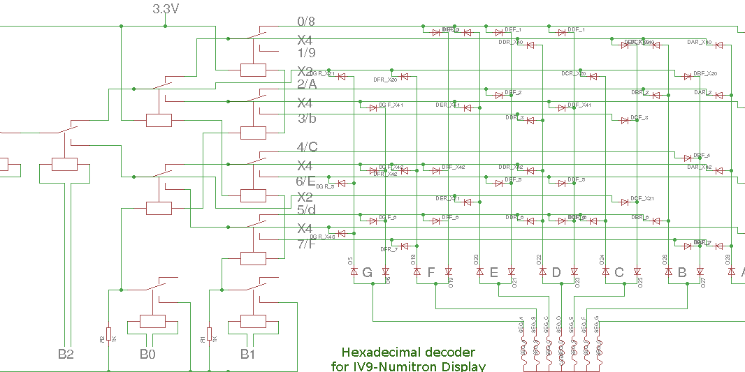
Since the circuit is a relay-diode circuit, it is logical to assume that the binary code is first sent to the binary decimal decryptor, at the output of which the code becomes positional, and then the fractional matrix converts the positional code into a seven-segment one. This is the most lazy way, but not optimal: more relays and diodes are needed. Yann Guidon reduced the number of both of them by using not positional, but more complex code, not too human-readable, but absolutely understandable to the diode matrix as an intermediate.
And since each segment of the rock indicator can be powered with voltage of any polarity, this matrix can still be optimized. See how the master realized its outputs on diodes connected in different directions. But that is not all. To the midpoint of a bipolar power source, he connected only the general output of the indicator. And the relays are powered by the voltage taken between the poles of this source, that is, 7.2V. To organize the inputs of the decoder used relay windings, untied from the rest of the circuit. In general, look:
By choosing the method of assembly of this scheme, you are given full scope. If you want to go on the beaten track - take the finished files for Eagle: and. You can use the breadboard.
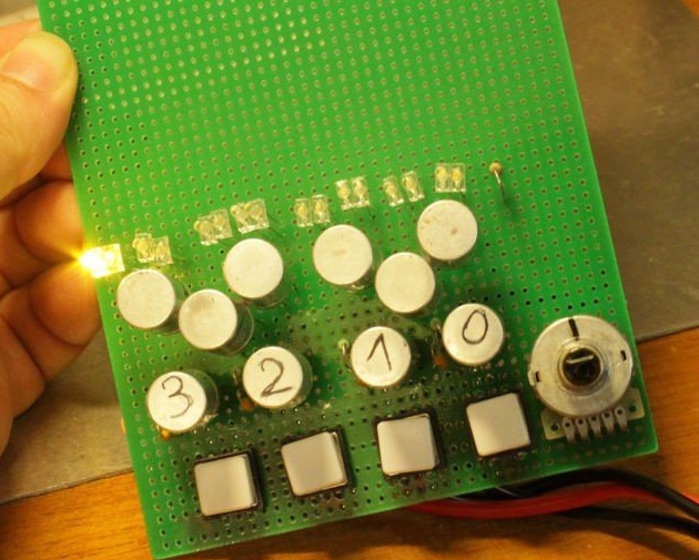
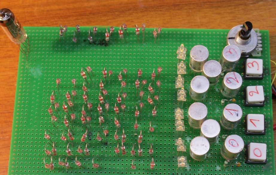
The master himself also decided not to be limited to one option. In one of them he used buttons to enter the binary code, and LEDs to indicate the intermediate one, which is convenient for debugging:
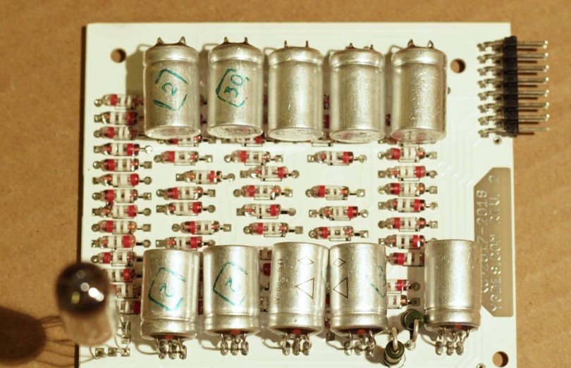
I left the buttons in another, and replaced the matrix diodes with old LEDs in metal cases, for example, AL102:
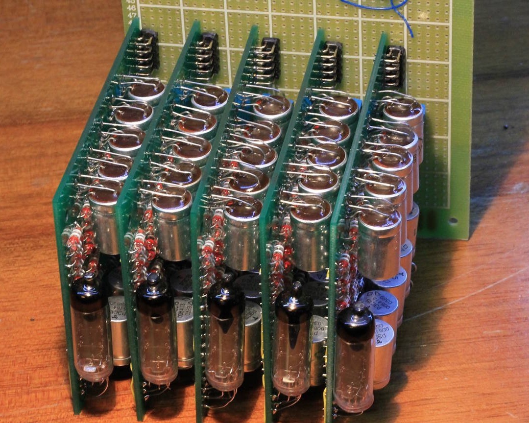
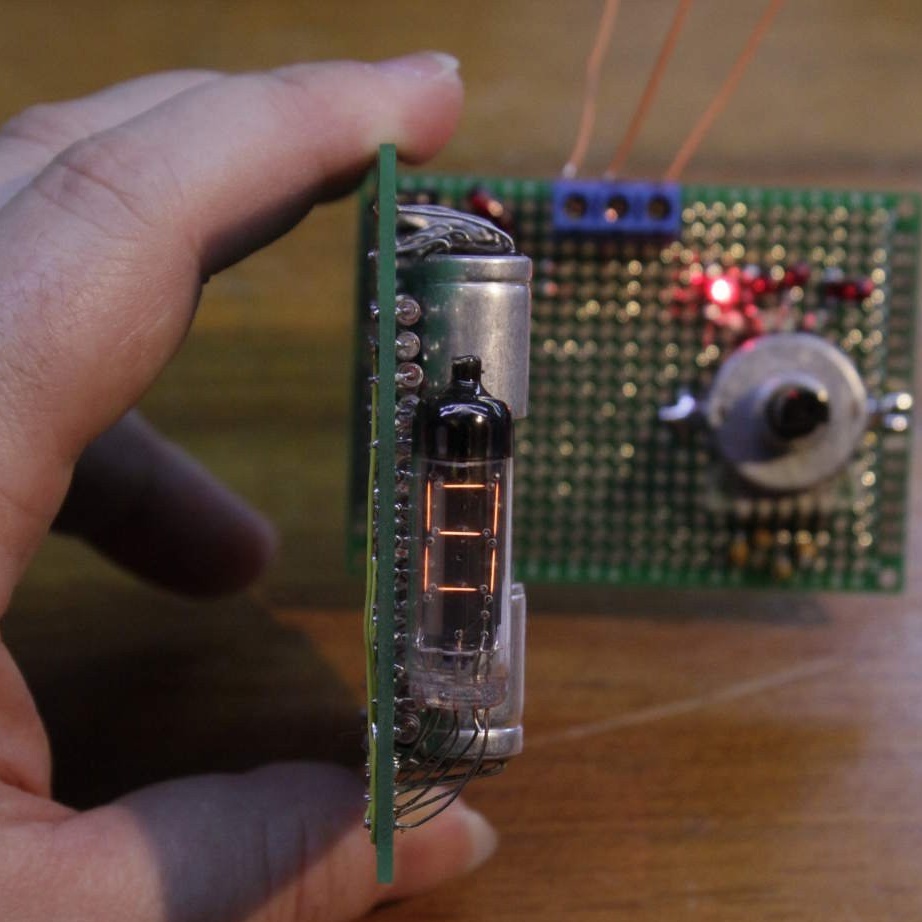
In the third, I made a board with a vertical indicator and a connector for supplying signals to inputs from the outside:
You can connect to it a test board with a binary code former using a dial switch:
And you can dial from them a multi-digit display with built-in decoders:
Perhaps the reader will be surprised that the indicator sometimes shows not numbers, but letters. This is normal. Four binary digits can encode sixteen combinations - from 0 to 15. Numbers from 0 to 9 are numbers, and from 10 to 15 - the letters A, B, C, D, E, F. Therefore, the hexadecimal number system is so wide and used in computer technology - it allows you to use everything, and not just some of these combinations, as it would be when using binary. Optimization again.
If you have already collected something on gas-discharge and luminescent indicators, the glow will surprise you with its simplicity in comparison with them. It's just an incandescent bulb, only multi-filament. If you don’t find one, take the small indicator lights and arrange them in the shape of the segments. The supply voltage of the bulbs should be half the voltage of the relay windings, the current should be less than the limit for diodes. If it is a little larger, you can take modern diodes - such for small ones, but at a higher current.
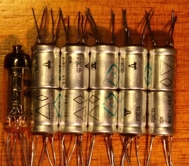
Let's see how Yann Guidon collects one of the device options. He begins by acquiring an indicator and ten relays:
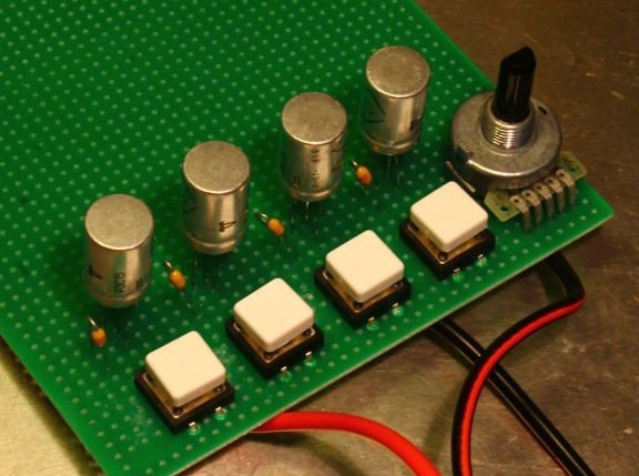
It solders two input devices to choose from: buttons and a thumb switch with a built-in binary encoder, as well as the first four relays, to the windings of which these input devices will be connected:
Installs the rest of the relays, connects them according to the diagram shown above, and the outputs of the decoder generating the intermediate code, loads the LEDs for debugging. At this stage, a bipolar source is not necessary, since there is no indicator yet whose common output must be connected to the midpoint of the power source.
Solder diode matrix and indicator. Everything works, but the matrix is not yet optimized, there are more diodes in it than it could be:
And finally, it optimizes it, getting what you already saw at the beginning of the article.
If you are going to make relay decoders (for example, clocks) only decoders, and the source of the binary signals of each category will be logic circuits or a microcontroller, the relay windings will need to be matched with them using transistor switches. To do this, you need to take a transistor of the P-N-P structure, connect the emitter to the negative of the signal source, the collector to one of the terminals of the relay winding, and its other output to the plus of the signal source. Shunt the winding with a diode in reverse polarity. Connect the transistor base with a 1-kilo-ohm resistor to the output of the microcircuit. Each decryptor will require four such keys.
And the display as in old science fiction films is ready!